
9 General requirements for pipes
9.1 Appearance
When viewed without magnification, the internal and external surfaces of the pipe shall be smooth, clean and free from scoring, cavities and other surface defects which would prevent conformity with this International Standard. The material shall not contain visible impurities. The ends of the pipe shall be cut cleanly and square to the axis of the pipe.
9.2 Opacity
If a pipe is required to be opaque for use in above ground applications, the wall of the pipe shall not transmit more than 0,2 % of visible light falling on it when tested in accordance with ISO 7686.
11 Mechanical characteristics of pipes
11.1 Resistance to hydrostatic pressure
11.1.1 Pipes
Resistance to hydrostatic pressure shall be verified using the induced stresses derived from the analysis of
the test data in accordance with ISO 9080. For a period of 10 h at 20 °C and at the time of 1 000 h at 20 °C, the 99,5 % LPL value shall be taken as the minimum stress level.
For a period of 1 000 h at 60 °C, the 99,5 % LPL value established from analysis of test data at 60 °C in
accordance with ISO 9080 can be taken as the minimum stress level. In case of a lack of data, alternatively, a value of 0,625 times the MRS value shall be taken as the minimum stress level.
When tested using either end cap type A or type B in accordance with ISO 1167-1, and using the combinations of test temperatures and induced stresses so derived, the pipe shall not fail in less than the times stated above.
See Annex A for the procedure to establish 20 °C test stress values for testing under provisional qualification.
11.1.2 Pipes with integral socket
When tested in accordance with ISO 1167, using the test procedure as given in 11.1.1, integral sealing ring sockets formed on pipes shall not fail in less than the time according to 11.1.1. The length of the pipe section shall meet the requirements or specification given in 11.1.1. Failure shall not occur in either pipe or socket sections. Data obtained is valid for pipe specified in 11.1.1.
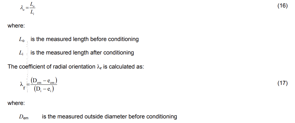
11.1.3 Pressure testing Pressure testing shall be conducted in accordance with ISO 1167-1 with the following provisions.
a) End fittings: testing may be conducted using either end cap type A or type B, including for reference
purposes. However, the same type of end caps shall be used for both acceptance and quality tests.
b) Number of specimens: one specimen shall constitute a test. In the event of a test failure, three more
specimens may be selected from the same batch and tested, and shall pass.
c) Conditioning times: testing may proceed directly following the conditioning times stated in ISO 1167-1.
d) Socket tests: when testing integral sockets or couplings in accordance with 11.1.2, the pipe spigot
inserted into the socket may be of different material or heavier gauge than the specimen under test. The
sealing ring may be restrained from blow-out by adhesive or mechanical means, provided such means do
not materially reduce the stress on the pressurized portion of the socket.
11.2 Resistance to external blows at 0 °C
Pipes shall be tested at 0 °C in accordance with ISO 3127, and shall have a true impact rate (TIR) of not more than 10 % when using masses given in Table 3. The radius of the striker nose shall be R = 12,5 mm.
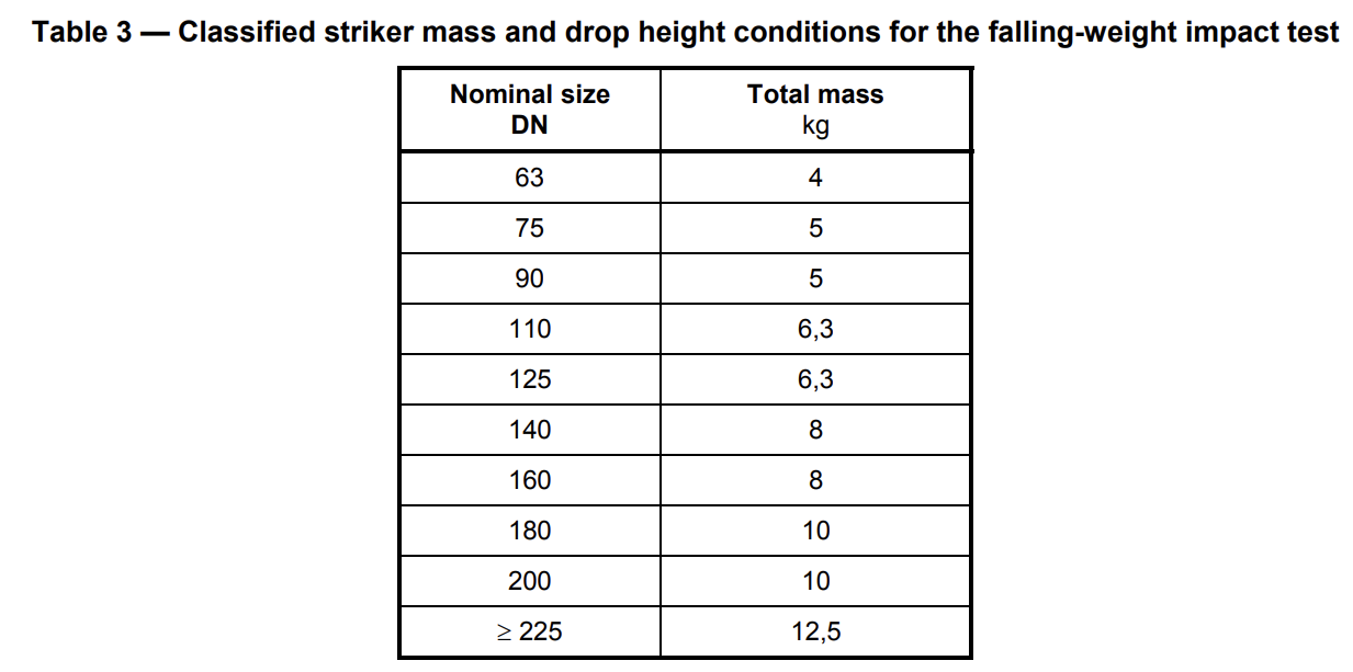
Drop height is 2 m.
NOTE 1 Masses are based on experience of pipe material classes 450 and 500. Masses for other pipe material classes are still under study.
NOTE 2 Impact characteristics can change over time. These values are applicable only at the time of manufacture.
11.3 Ring stiffness
The ring stiffness of pipes conforming to this International Standard may be determined in accordance with ISO 9969.
Pipes of stiffness less than 4 kN/m2 might not be suitable where high vacuum or external pressure could be developed, and could need special installation techniques where installed below ground.
National regulations and/or national practices on use of specific fittings may require minimum stiffness of
pipes.
NOTE Minimum stiffness of pipes could be required for installation with some type of fittings
The calculated nominal stiffness of the pipes is given in Annex D.
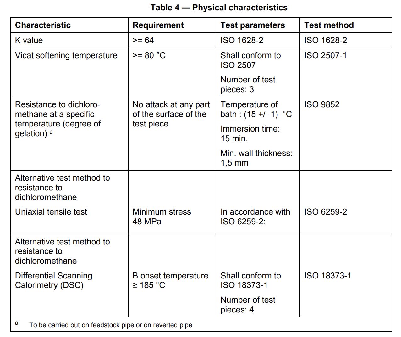
12 Physical characteristics
When tested in accordance with the test methods as specified in Table 4 using the indicated parameters, the pipe shall have physical characteristics conforming to the requirements given in Table 4.
13 Mechanical characteristics of assemblies, including joints
13.1 Assemblies with non-end-load-bearing joints
The following types of assemblies with non-end-load-bearing joints shall fulfil the fitness for purpose
requirements given in 13.2 to 13.5 and Tables 5, 6 and 7, as applicable:
a) integrally socketed PVC-O pipe to pipe assemblies with elastomeric ring seal joints conforming to this
International Standard;
b) metal fitting and PVC-O pipe assemblies with elastomeric ring seal joints;
c) metal valve and PVC-O pipe assemblies with elastomeric ring seal joints;
d) mechanical joint assemblies with PVC-O pipes.
13.2 Short-term pressure test for leak tightness of assemblies
13.2.1 Test procedure
When an assembly with one or more elastomeric sealing ring type joints is tested using a hydrostatic pressure and angular deflection in accordance with ISO 13845, and the test conditions given in Table 5, the assembly shall conform to the requirement given in Table 5.
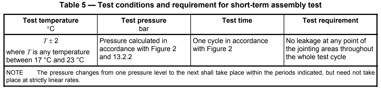
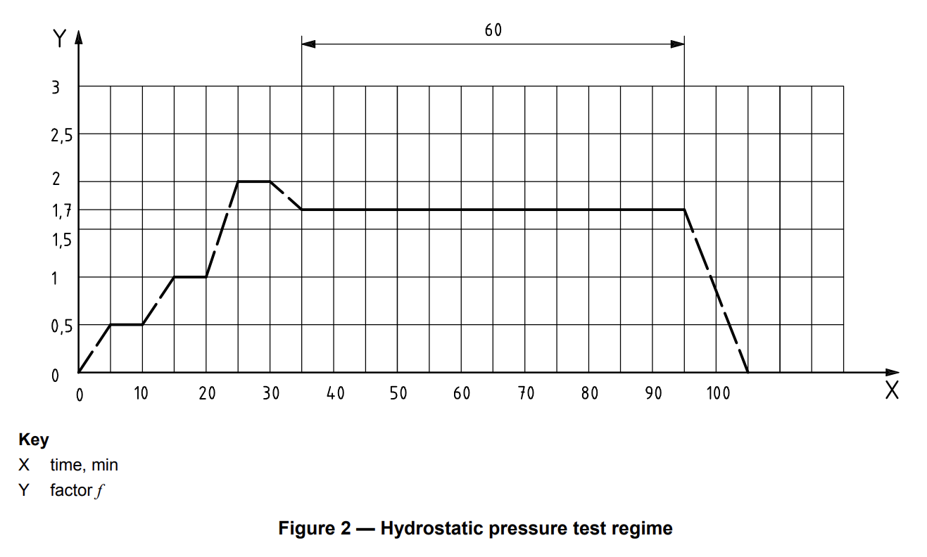
13.2.2 Test pressure
The test pressures pT shall be calculated by multiplying the factor ƒ indicated in Figure 2 by the nominal
pressure PN, i.e. by using the following equation:
pT = ƒ × PN
where
PN is the nominal pressure
f is the multiplying factor
pT is the test pressure
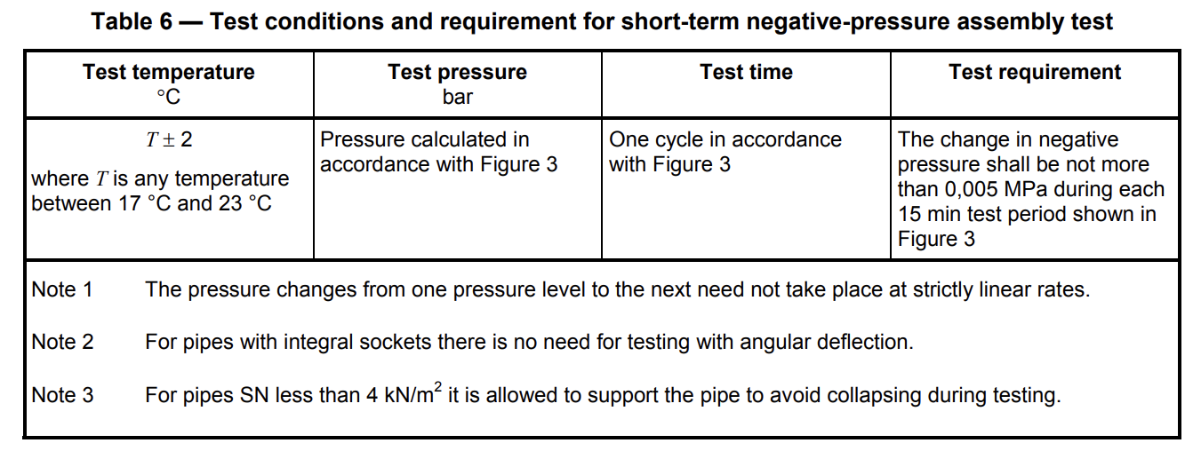
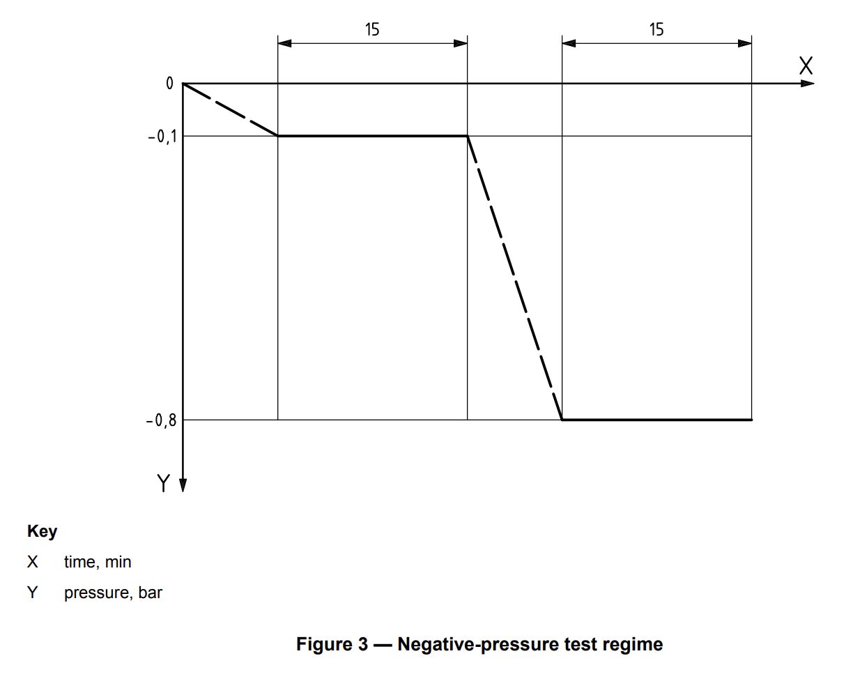
13.3 Short-term negative pressure test for leak tightness of assemblies
When an assembly with one or more elastomeric sealing ring type joints is tested using a negative pressure with angular deflection and the deformation in accordance with ISO 13844 and the test conditions given in Table 6, the assembly shall conform to the requirement given in Table 6.
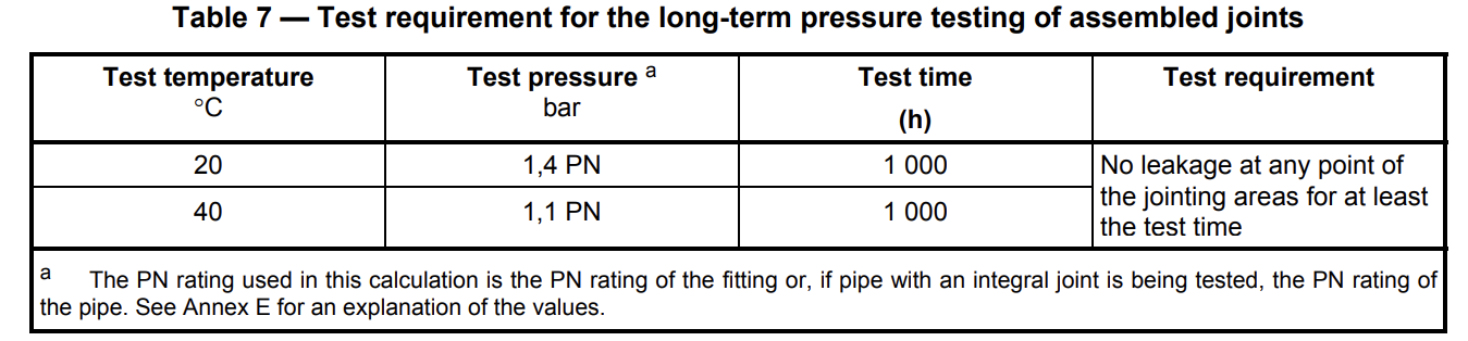
13.4 Long-term pressure test for leak tightness
When an assembly with one or more joints selected from elastomeric sealing ring type sockets and other
end-load-bearing and non-end-load-bearing joints for oriented PVC-U components for a piping system is
tested in accordance with ISO 13846, using the test conditions given in Table 7 for the test temperatures of 20 °C and 40 °C, the assembly shall conform to the requirement given in Table 7.
13.5 End-load-bearing joints
Pressure and bending test for leak tightness and strength When end-load-bearing joints having one or more sockets (see note) and fitted with one or more elastomeric sealing rings together with one or more locking rings to withstand the longitudinal forces resulting from the application of internal hydraulic pressure are tested in accordance with ISO 13783 at a single ambient temperature of (T ± 2)°C (where T is any temperature between 17 °C and 23 °C), the joint shall remain leak tight throughout the whole of the test period.
NOTE Such joints are usually, but not necessarily, in the form of double sockets.
14 Elastomeric seals
Elastomeric seals used for joining components shall conform to both of the following requirements:
a) the rings shall conform to the material requirements specified in ISO 4633;
b) the rings shall be free from chemical agents (e.g. plasticizers) that could have a detrimental effect on the pipes or fittings, or on the quality of the water.
Annex D
(informative)
Ring stiffness of pipes
D.1 Calculation of initial ring stiffness
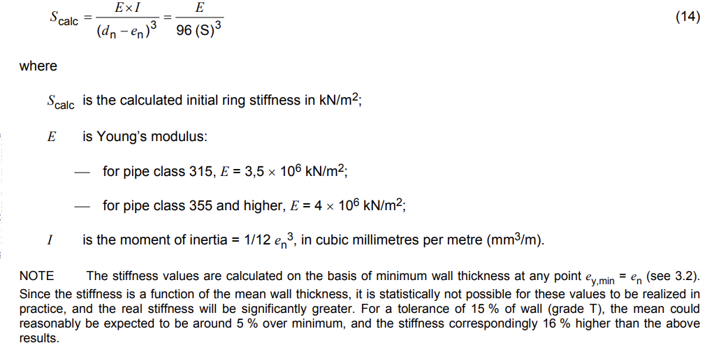
For design purposes, the calculated initial ring stiffness of the pipes can be derived from Table D.1.
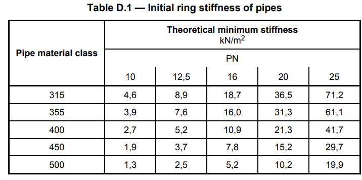
This value has been calculated from the formula
D.2 Negative pressure capability of pipes
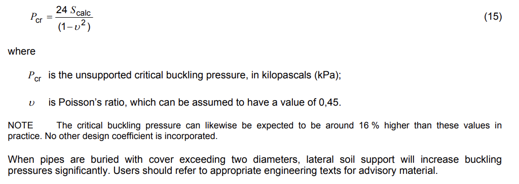
Pipes may be subject to unstable buckling under negative pressure conditions due to vacuum and/or external or groundwater pressure, if unsupported by soil or other lateral stiffening devices.
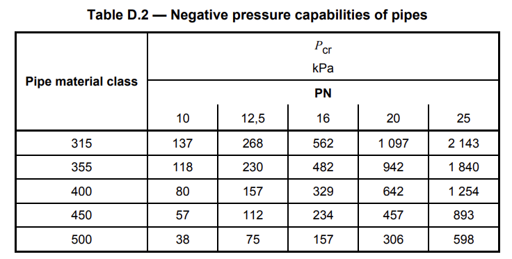
These values have been calculated from the formula
Annex E
(informative)
Determination of the long-term test pressure by creep consideration
The calculation for the test pressures for the long-term leak tightness test of PVC-O assemblies is based on the method as specified in ISO 1452-5:2009, Annex B.
For details of the calculation of the factors, see ISO 1452-5:2009, Annex B, for σs = 12,5 MPa.
It is considered that for PVC-O pipes these factors are the worst case. Where a manufacturer has made
available stress/strain data, the actual factors may be derived from this information in accordance with the
method given in ISO 1452-5: 2009, Annex B.
Annex F
(informative)
Determination of axial and tangential orientation factor
F.1 Principle
A piece of pipe is measured under identical conditions before and after heating in the oven at a specified
temperature for a specified duration.
The reversion is calculated as the percentage variation in length, diameter and wall thickness in relation to the initial values. The test pieces are examined on any changes in appearance e.g. bubbles and cracks.
F.2 Method
The axial and tangential orientation factor shall be determined conforming to ISO 2505.
F.3 Test parameters
Specimen length : 300 mm
Distance between the marks : 200 mm
Test temperature : 150 ± 2°C
Medium : air
Immersion time : 60 or 120 minutes
Number of test pieces : 3
F.4 Test procedure
The test is carried out according to ISO 2505.
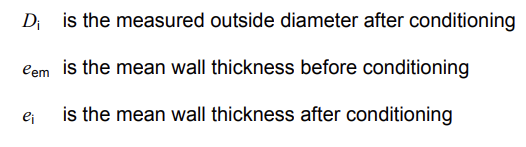
The coefficient of axial orientation λa is calculated as:
Check our YouTube channel for videos of the products, ask any questions on WhatsApp: