
3 Principle
A test piece, consisting of PVC-U pipes mounted into a PVC-U double socket coupler, is exposed to a specific cycle of internal hydrostatic pressures for specific test periods and at a specific temperature while the assembly is simultaneously subjected to a lateral bending force.
4 Apparatus
4.1 A pressure control device, connected to the test piece and capable of applying a variable internal hydrostatic pressure of at least 2,5 times the nominal pressure (PN) of the PVC-U pipe and joint assembly.
4.2 A vacuum pump, capable of applying a negative internal pressure of at least -0,8 bar
(-0,08 MPa).
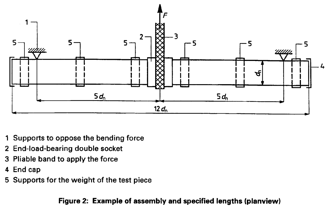
4.3 A loading jig, capable of applying a horizontal bending force to an assembled test piece while it is subjected to an internal hydrostatic pressure. The jig includes vertical supports equally spaced at 5dn on either side of the axis of the horizontal force to restrain the test piece so that the horizontal force will induce bending, and horizontal supports beneath the test piece, to enable horizontal axial alignment of the test piece components. The supports have a low friction surface, to minimize inhibition of axial bending. An example of a test arrangement is shown in figure 2.
The length of the pipe sections and the total length of the test pieces shall conform to the values given in figure 2.
4.4 Gauges, for measuring the internal hydrostatic pressure and the applied bending force, each having an accuracy of ±1 % at the measured values.
5 Test piece
The test piece shall consist of two PVC-U pipe sections mounted into the PVC-U end-loadbearing double socket coupler to be tested. The assembly shall be carried out in accordance with the instructions of the manufacturer of the double socket coupler.
The pipes and the double socket shall be of the same nominal pressure.
NOTE: The mean outside diameter of the pipes should preferably conform to the minimum specified value, and the socket dimensions (mean inside diameter and the diameter of the groove for housing the sealing ring) should preferably conform to the maximum allowable values stated by the manufacturer in order to have dimensions as close as possible to the extreme limits of their relevant tolerances.
6 Procedure
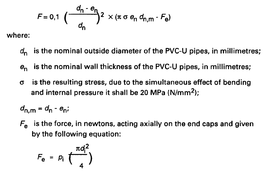
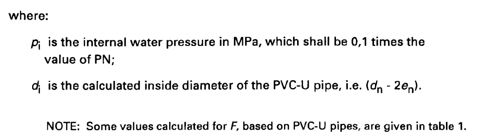
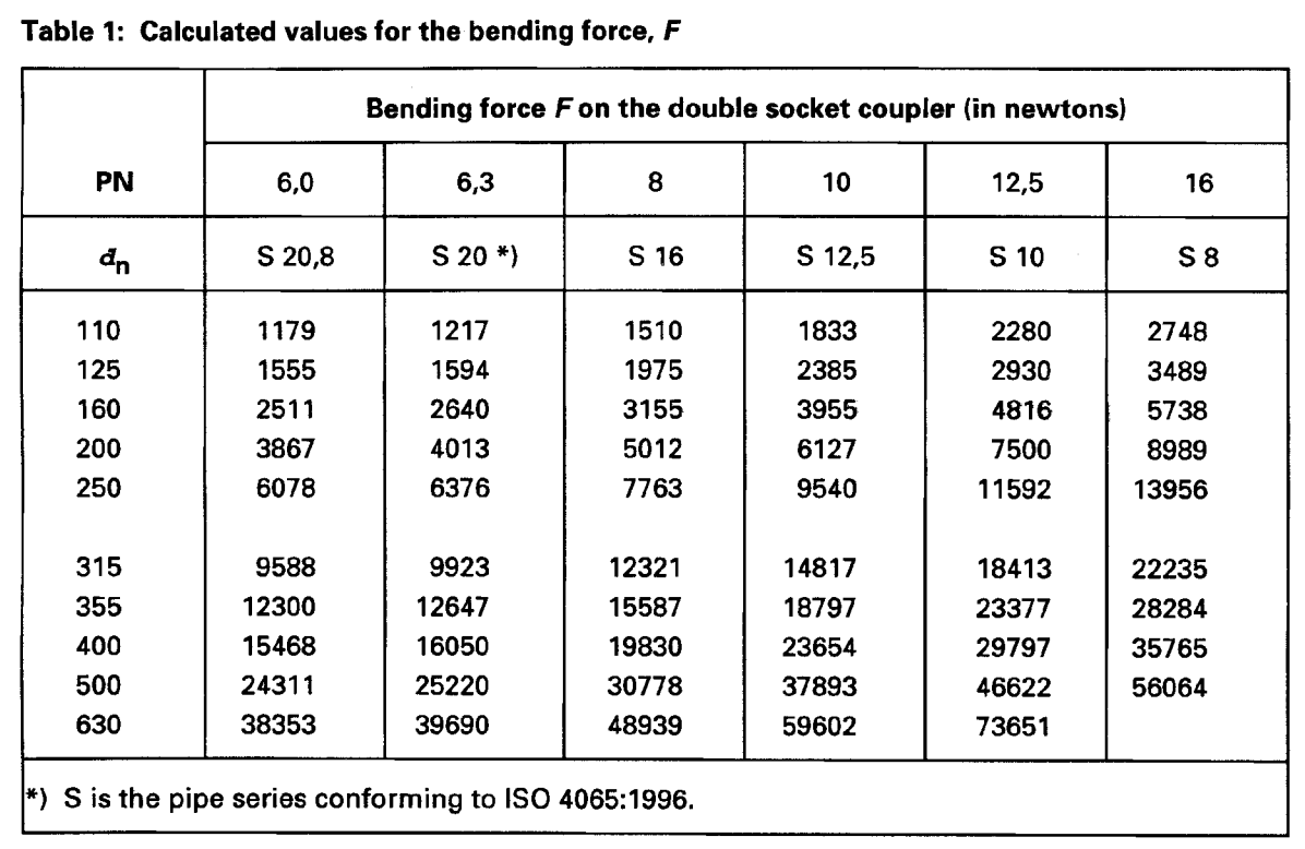
6.1 Calculate the bending force F using the following equation:
6.2 Lay the assembled test piece on the supports, ensuring that the pipes and the coupler are in axial alignment (see figure 2).
6.3 Fill the test piece with water at (20 ± 5) °C and release all air. Allow the assembly to condition for 60 min to ensure equalization of temperature.
6.4 Carry out the procedure given in 6.5 at any ambient temperature between 15 C and 25 C while maintaining this ambient temperature within ±2 C and examining the joints for leakage during the whole test cycle.
6.5 Carry out the following test procedure in accordance with the schematic arrangement shown in figure 3, which is not intended to require strictly linear rates of change in pressure or force, and by maintaining each static pressure and bending force within (+5/0)%.
At A: increase the water pressure over a period of 5 min to 1 times [PN], and maintain this pressure for 5 min.
At B: increase the water pressure over a period of 5 min to 2,5 times [PN], and maintain this pressure for 5 min.
At C: reduce the water pressure over a period of 5 min to 1 times [PN].
At D: apply the calculated value of the bending force, F, in the horizontal plane over a period of 5 min whilst maintaining the internal pressure of 1 times [PN].
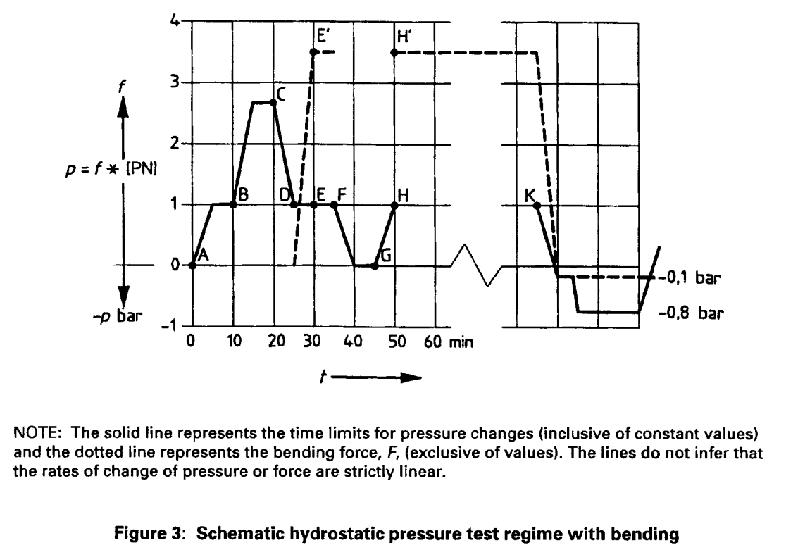
At E: maintain the water pressure at 1 times [PN] for a further period of 5 min whilst maintaining the bending force F.
At F: reduce the water pressure to atmospheric pressure within 5 min and ensure that the deflection of the pipe is maintained constant for a further period of 5 min.
At G: increase the water pressure within a period of 5 min to 1 times [PN].
At h: adjust the bending force, F, to its original value. (The angle of deflection will normally be a little greater than at E.) Repeat the cycle from E to H a further nine times.
At K: at the end of the 10th cycle, release the bending force and drain the water from the assembled test piece. Apply a negative pressure to the test piece until a constant pressure of (-0,1 ± 0,02) bar is achieved. Isolate the vacuum pump from the test piece, and observe the pressure for 15 min. Apply a further negative pressure to the test piece until a constant pressure of (-0,8 ± 0,02) bar is achieved, then isolate the vacuum pump from the test piece, and observe any increase in pressure for a further 15 min.
6.6 On completion of the test disassemble the joints and examine all parts for details of any cracks and deformations and record the results.