
1 Scope
This part of ISO 1167 specifies a general test method for determining the resistance to internal hydrostatic pressure at a given temperature of thermoplastics pipes, fittings and piping systems for the transport of fluids.
The method accommodates water-in-water, water-in-air and water-in-liquid tests.
4 Principle
After conditioning, test pieces are subjected to a specified constant internal hydrostatic pressure for a specified period of time or until a test piece or pieces fail.
Throughout the test, the test pieces are kept in an environment at a specified constant temperature: this is either water (“water-in-water” test), another liquid (“water-in-liquid” test) or air (“water-in-air” test).
The following test parameters shall be specified by the standard or specification making reference to this part of ISO 1167:
a)the type of end cap to be used (see 5.1 and ISO 1167-2:2006, 4.1);
b)the test temperature;
c)for evaluation purposes, the SDR or S-series or size of pipe or fitting to be used;
d)the number of test pieces;
e)the test pressure, p, or the circumferential (hoop) stress, σ, to be induced by the test pressure;
f)the type of test, i.e. “water-in-water”, “water-in-liquid” or “water-in-air”;
g)the duration of the test under pressure and the criteria for a failure;
h)the requirements, or patterns of requirements, if any, which determine the initiation of additional testing.
5 Apparatus
5.1 End caps, fixed to the ends of the test piece. By means of an appropriate system or procedure, end caps shall allow sealing and connection to the pressurizing equipment and shall allow purging of the air before testing.
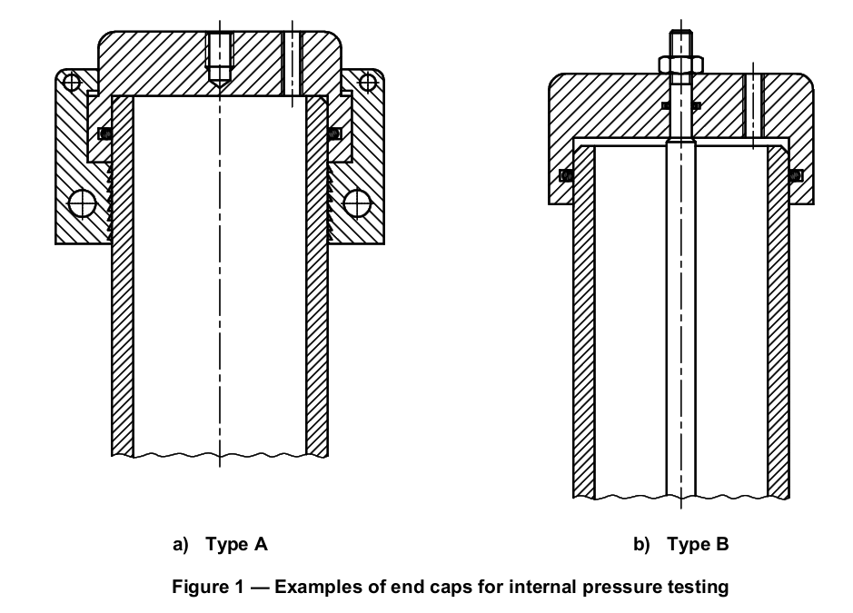
The end caps shall be one of the following types.
Type A: fittings rigidly connected to the test piece but not to each other, and hence transmitting the hydrostatic end thrust to the test piece, e.g. as shown in Figure 1, or equivalent. They may comprise flanged plates on the ends of a large diameter pipe, optionally fused when flanges, caps, plugs or plates are of a compatible material to the test pieces.
Type B: sockets, made of metal, fitted with joints ensuring sealing onto the external surface of the test piece and connected to one another, and hence not transmitting the hydrostatic end thrust to the test piece. They may comprise one or more metal rods, see Figure 1, allowing sufficient longitudinal movement at the ends of the test pieces, to avoid buckling due to thermal expansion. If external rods are used, contact of the outside surface of the test piece with one or several rods shall be avoided during the test. In this case, the test shall be disregarded.
Other than toothed grips, any sharp edges which would come into contact with the outside surface of the pipe shall be rounded off.
The constituent material of the end cap might have an adverse effect on the test piece under test and such materials should therefore be avoided as far as possible.
For testing of components, the end caps shall be replaced by pressure-tight devices as specified in ISO 1167-3.
End caps of type A shall be used for determination of the long-term hydrostatic strength of materials in accordance with ISO 9080.
NOTE: It is recognized that times to failure can be different depending upon the type of end caps used.
5.2 Tank, filled with water or other liquid, kept at a constant temperature as specified in the referring standard to within ± 1 °C, or oven, the temperature of which shall be kept at the specified value to within -1…+2C
When an environment other than water is used, necessary precautions shall be taken, in particular those concerning safety and any interaction between liquid and the material(s) of the test piece.
When environments other than water are used, tests which are intended to be comparative shall be carried out in the same environment.
As the results are strongly influenced by temperature, the tolerance on temperature should be kept as small as possible within the specified limits e.g. by using forced circulation of the fluid.
When testing in air, the pipe surface temperature should be checked in addition to the air.
Potable water should be used and it is necessary to avoid contamination of the water by any substance likely to affect the results, e.g. detergents, lubricants.
5.3 Support or hangers, enabling test pieces to be placed in the tank or oven (5.2) such that contact between them or with the sidewalls of the tank/oven is avoided as far as possible so as not to influence the test results.
5.4 Pressurizing equipment, capable of applying the required pressure gradually and smoothly in accordance with Clause 9 and then of keeping this indicated (or measured) pressure to within -1….+2% for the duration of the test.
As the results are strongly influenced by pressure, the tolerance on pressure should be kept as small as possible within the specified limits.
The pressure should preferably be applied individually to each test piece. However, the use of equipment enabling the pressure to be applied simultaneously to several test pieces is also permitted if there is no
danger of interference when failure occurs (e.g. by the use of an isolation valve or a test based on the first failure in a batch).
To maintain the pressure within the specified tolerance, a system should be introduced which automatically controls the pressure within this specified tolerance (e.g. due to expansion of the test piece).
5.5 Pressure measurement devices, capable of checking conformity to the specified test pressure. The range of the gauge shall be such that the required pressure setting shall lie within the calibrated range of the device used (see Clause 7).
The pressure measurement devices shall not contaminate the test fluid.
In case of dispute, the reference level of the pressure device shall be equal to the water level in the tank. Master gauges for calibration of the apparatus should be used.
It is recommended to use equipment which is capable of stopping the timer (5.8) in event of failure or leakage and closing the pressure circuit to the test piece concerned.
5.6 Dimension measuring equipment, conforming to ISO 3126.
5.7 Temperature measuring equipment, capable of checking conformity to the specified test temperature (see 5.2).
5.8 Timer, capable of recording the duration of the pressure applications up to the moment of failure or leakage, to within 0,5 % of the expected testing time.
6 Test pieces
6.1 Preparation of test pieces
The preparation of test pieces shall conform to ISO 1167-2, ISO 1167-3 or ISO 1167-4, as applicable. Measure and record test piece component parameters, e.g. preparation conditions, dimensions, as necessary.
6.2 Number of test pieces
Prepare a minimum of three test pieces unless otherwise specified in the referring standard or specification.
7 Calculation of test pressure
7.1 General
For material testing, the test pressure shall be calculated from a given circumferential hoop stress and based on the measured dimensions of the test piece, see 7.2.
For pipe testing, the test pressure shall be calculated from a given circumferential hoop stress and using one of the following options, given by the referring standard or specification:
a) based on the measured dimensions of the test piece, see 7.2;
b) based on the nominal dimensions of the test piece, see 7.3.
For testing of components, the test pressure shall be as given in the referring standard.
For testing of assemblies, the test pressure shall be calculated from a given circumferential hoop stress and based on the SDR of the pipe(s) used for the test piece, see 7.4, unless a test pressure is specified by the referring standard or specification.
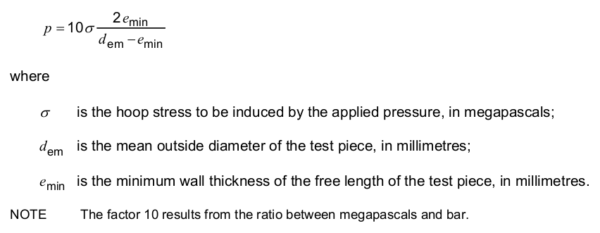
7.2 Pressure calculations based on the measured dimensions of the test piece
Calculate the test pressure, p, in bar 2), to three significant figures, using the following equation:
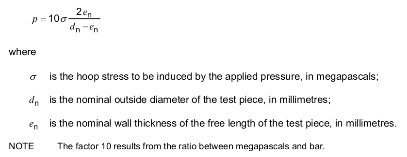
7.3 Pressure calculations based on the nominal dimensions of the test piece
Calculate the test pressure, p, in bar2), to three significant figures, using the following equation:
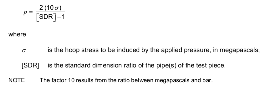
7.4Pressure calculations based on SDR of pipe(s) of the test piece
Calculate the test pressure, p, in bar2), to three significant figures, using the following equation:
8 Calibration and accuracy of the apparatus
The temperature and pressure control systems and the equipment for measuring temperature, pressure and time shall be capable of maintaining the values within the specified limits and shall be calibrated.
The accuracy of the apparatus shall be considered such that the requirements for temperature, pressure and time are fulfilled.
9 Conditioning
Prepare the test pieces, removing any traces of dirt, oil, wax or other contamination, and fit them with the end caps (5.1) specified for the test.
Measure and record the free length of the pipes of the test piece l0, as appropriate.
Fill the test pieces with water, which may be preheated to a temperature not more than the test temperature.
After filling thetest pieces, immerse them in a water bath or place them in an oven at the temperature specified by thereferring standard and condition for a period in accordance with Table 1. When conditioning at
temperatures inexcess of 100 °C sufficient pressure shall be applied to prevent boiling.
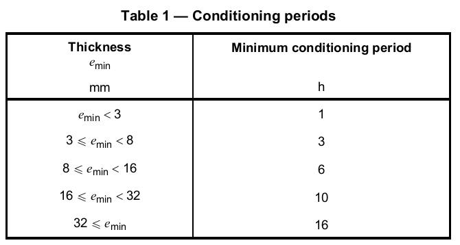
NOTE It is recognized that extended conditioning periods beyond those specified in Table 1 could influence the test results.
Record the actual conditioning time.
The test pieces shall not be tested within the period of time after their manufacture specified in the referring standard. Otherwise, a minimum period of 24 h after production shall be observed.
10 Test procedure
10.1 Select the type of test, i.e. “water-in-water”, “water-in-air”, or “water-in-liquid”, as specified by the referring standard or specification.
Measure and record the time taken to pressurize the test piece as follows.
Connect the test pieces to the pressurizing equipment (5.4) and bleed off the air. After conditioning, progressively and smoothly apply the test pressure as calculated in Clause 7, in the shortest time practicable between 30 s and 1 h depending upon the material, the size of the test piece and the capability of the pressurizing equipment.
When the test pressure is achieved, record the time or reset the timer as necessary to begin to measure the period for which the specified pressure is maintained in the test piece(s).
10.2 Keep the test piece suspended in the thermally controlled environment. Maintain a constant temperature (see the referring standard or specification) and observe the temperature tolerances specified in 5.2 until testing ceases in accordance with 10.3 or 10.4 as applicable.
10.3 The test is terminated either when the specified duration is reached, or when a failure or leak occurs in the test piece, in which case record the time to failure, unless the procedure given in 10.4 is applicable.
If a failure occurs, record the type, i.e. brittle, or ductile, or other.
NOTE Failure is “brittle” if no visible yield deformation has occurred in the failure zone. If the failure is accompanied
by a yield deformation in the failure zone, visible without magnification, it is of the “ductile” type. For some materials, brittle failure could be indicated by weeping at the pipe surface.
In the event of equipment failure, tests which have been ongoing for a period of 500 h to 1 000 h may be continued providing the equipment is reinstated within one day. For tests which have been ongoing for a period of more than 1 000 h, the test may be continued, provided the equipment is reinstated within three days. The time during which the equipment is not able to function normally shall not be included in the test time. Test interruptions shall be recorded in the test report.
10.4 If a break occurs in the test piece at a distance of less than 0,1 l0 from an end cap, disregard the result and repeat the test using another test piece [l0 is the free length of the pipe(s) of the test piece, see ISO 1167-2 or ISO 1167-4].
When testing components, if there is a leakage outside of the component itself (failure of the seal or bursting of the pipe), or any failure associated with grooves machined and indicative of inappropriate groove design and/or machining conditions, repeat the test — if necessary using other components — such that the assembly remains watertight for the minimum period required for the test.
11Test report
Thetest report shall include the following information:
a)a reference to this and other relevant parts of ISO 1167;
b)the complete identification of the sample;
c)type of the material or materials of each component of the test piece;
d)the nominal dimension of each component of the test piece;
e)the measured dimensions, e.g. minimum wall thickness, of each component of the test piece and free length of the pipe(s), as appropriate;
f)the conditions of preparation of test pieces (e.g. conditions of fusion); for injection-moulded test pieces: details of any conditioning of the material before moulding, of the injection-moulding machine used and of the moulding conditions, as appropriate;
g)the test temperature and accuracy of its measurement;
h)the stress applied and/or the applied test pressure;
i)the nature of the environment (air, water or liquid and, in the case of the latter, the liquid used);
j)the type of end cap (see 5.1) and, in the case of components, the type of pressure-tight device;
k)the number of test pieces tested;
l)the conditioning time (see Clause 9) and, if required, the time taken to pressurize the test piece (see 10.1);
m)the test duration at the test pressure (see 10.1 and 10.3);
n)in the event of failure, the type of failure;
o)the observations made during and after the test;
p)any factors that could have affected the results, such as any incidents, test interruptions or any operating details not specified in this part of ISO 1167;
q)identification of the test unit;
r)the date of the test or dates between which the test was conducted.