
2 Principle
A joint assembly as test piece consisting of a PVC-U pipe mounted into a PVC-U socket is subjected, within a specified temperature range, to a specified internal pressure regime for a specified test period whilst the pipe is also subject to an angular deflection in the socket. While under pressure the test piece is monitored for signs of leakage.
NOTE It is assumed that the following test parameters are set by the standard making reference to this standard:
a) the test pressure and pressure/time regime (see 3.2 and 5.6);
b) the number of test pieces to be used (see 4.2).
3 Apparatus
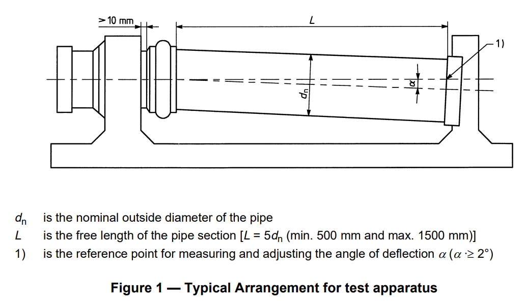
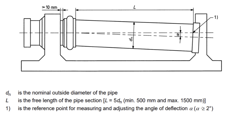
3.1 Framework, comprising at least two fixing devices, one of which is movable to allow angular deflection to be applied to the pipe within the socket. A typical arrangement is shown in figure 1.
3.2 A pressure control device, connected to the test piece and capable of applying and maintaining a variable internal hydrostatic pressure of up to at least twice the nominal pressure of the PVC-U pipe and joint assembly.
3.3 Pressure measuring device, capable of checking conformity to the specified static pressure values (see 5.6 and Figure 2).
4 Test pieces
4.1 Preparation
The test piece shall comprise an assembly of a PVC-U pipe section mounted into the socket of the component to be tested.
The assembly shall be carried out in accordance with the socket manufacturer’s instructions.
A pipe of the same nominal pressure as that of the socket shall be used for the test.
The length of the pipe section shall be such that the free length, L, between the socket mouth and the end-seal is equal to five times the nominal outside diameter, dn, of the pipe with a minimum of 500 mm and a maximum of 1500 mm.
NOTE The mean outside diameter, dem, of the pipe should preferably conform to the minimum specified value, and the socket dimensions (mean inside diameter, dim, and the diameter of the groove for housing the sealing ring) should preferably conform to the maximum values stated by the manufacturer, in order to have dimensions as close as possible to the extreme limits of their relevant tolerances.
5 Procedure
5.1 Secure the socket, without any deformation, to the solid framework and align the pipe section with the axis of the socket.
5.2 By inclining the pipe in the test apparatus, determine the free angle of deflection, Alfa, which the joint can tolerate without the application of force.
If Alfa>= 2°, firmly anchor the pipe to maintain the deflected pipe in this position for the remainder of the test.
If Alfa< 2°, carry out the test at a deflection of 2° by forcing the pipe to that degree of deflection.
5.3 Fill the test piece with water at a temperature of (20 ± 5) °C and release any trapped air.
5.4 Condition the test piece for a period of at least 20 min to ensure equalisation of temperature.
5.5 While testing in accordance with 5.6:
a) maintain the ambient temperature within ± 5 °C of any temperature between 15 °C and 25 °C;
b) examine the joint during the whole test cycle and record any sign of leakage.
5.6 Unless otherwise specified in the standard referring to this test method, apply the hydrostatic pressure test regime shown in Figure 2 so that the specified static pressures are maintained within a permitted deviation of (+5/0)%.

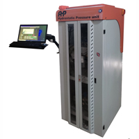
- According to ISO 1167 , ASTM D1598, ASTM D 1599 and ISO 13845
- European pump, sensors and valves
- Laptop and software is included
- Report out in MS WORD
- Manual charge and discharge
- Automatic pressure control
- Pressure rate control
- Water circulation system
- Digital temperature controller
- Airless system
- Maximum accuracy, a long service life and a user-friendly system, combined with flexibility
- High-precision pressure regulation, selectively regulated input pressure in each Line
- All metal components that come in contact with the medium is brass ans SS304
- Quick system calibration easily by the operator and calibration data saved in the controller modules
- Convenient operation, evaluation of results and clear visualization via Labview and windows based software
- Operator access to all important settings from the front panel
- Each station can be individually isolated from the supply pressure for service purposes
- PLC based control of the pressure channels
- Pressure gauge for checking each line actual pressure
- High-quality unit components guarantee long service life
- Along with AHP data logging software quarantine keeping of data in power break cases
- Ramp control capabilities for each line pressure
- European components of valves, sensors and pump
- Including high pressure accumulators
- Including the angular deflection framework (Requested size of customer-this frame work will be quoted separately)
- End caps for sample sizes will be quoted separately
Check our YouTube channel for videos of the products, and ask any questions on WhatsApp: