5 Apparatus
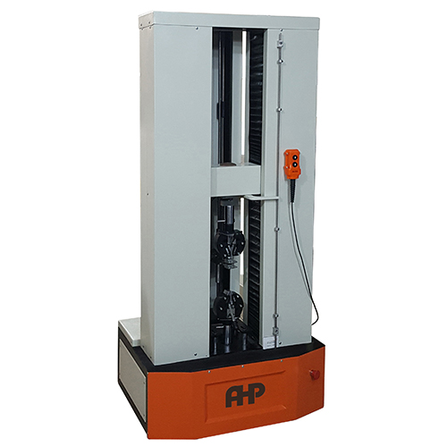
5.1 Compressive testing machine, capable of a constant rate of crosshead movement, via a pair of
parallel plates (5.2), as appropriate to the nominal diameter of the pipe in conformance with Table 1, with
sufficient force and travel to produce the specified diametric deflection (see Clause 8).
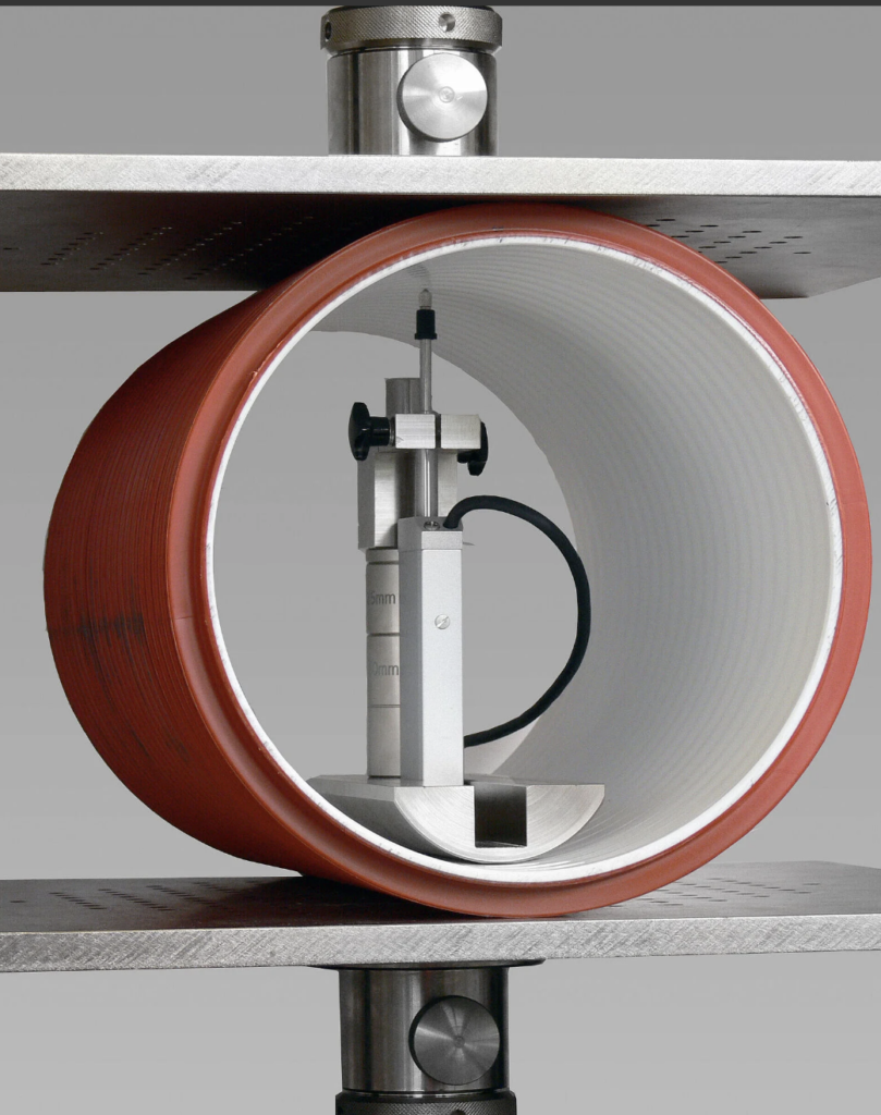
5.2 A pair of hard and rigid plates, through which the testing machine can apply the necessary force, F,
to the test piece.
The plates shall have flat, smooth and clean surfaces for contact with the test piece.
The stiffness and hardness of each plate shall be sufficient to prevent bending or deformation to an extent that would affect the results.
The length of each plate shall be at least equal to the length of the test piece. The width of each plate shall not be less than the width of the contact surface with the test piece while under load plus 25 mm.
5.3 Dimensional measuring devices, capable of determining
⎯ individual values for the length of a test piece (see 6.2.2 and 6.2.3) to within 1 mm,
⎯ the inside diameter of a test piece to within 0,5 %, and
⎯ the change of inside diameter of a test piece in the direction of loading with an accuracy of 0,1 mm or 1 % of the deflection, whichever is the greater.
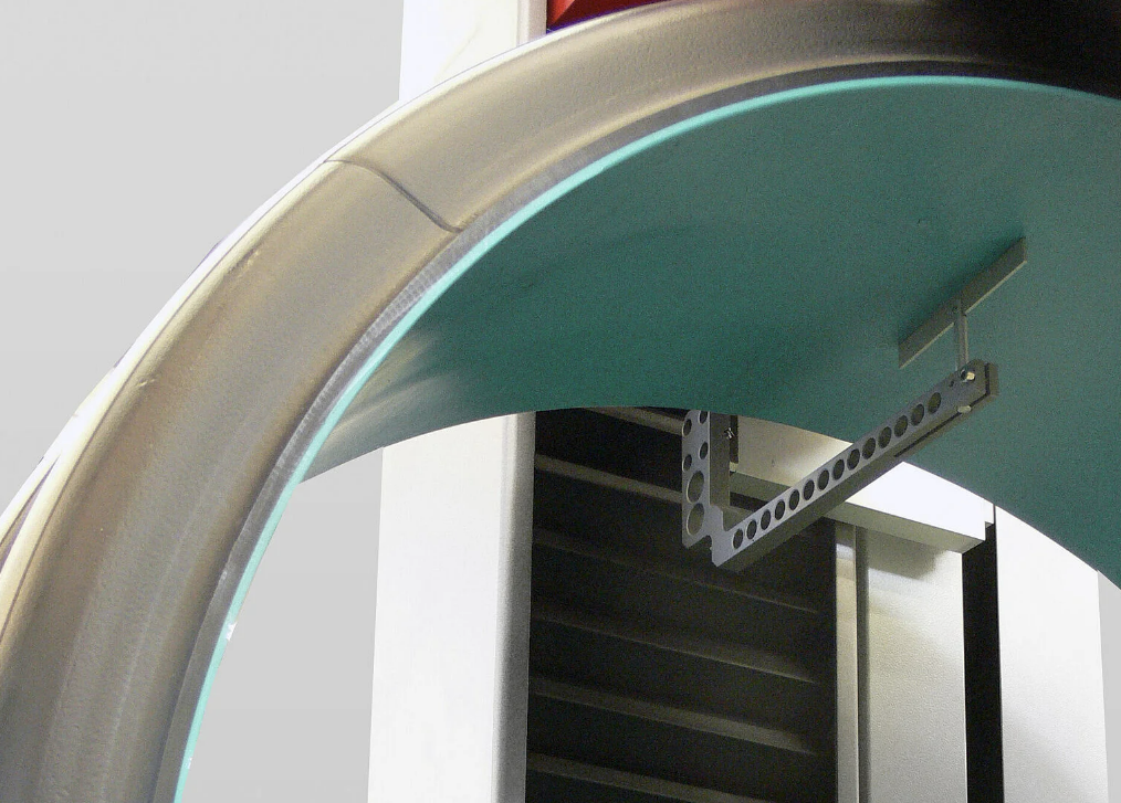
An example of a device for measuring the inside diameter of corrugated pipe is shown in Figure 1.
5.4 Force measuring device, capable of determining to within 2 % the force necessary to produce a
deflection of up to 4 % of the test piece.
6 Test pieces
6.1 Marking and number of test pieces
The pipe of which the ring stiffness is to be determined shall be marked on its outside with a line along one generatrix over its entire length. Three test pieces, a, b and c, respectively, shall be taken from this marked pipe such that the ends of the test pieces are perpendicular to the pipe axis and their lengths conform to 6.2.
6.2 Length of test pieces
6.2.1 The length of each test piece shall be determined by calculating the arithmetic average of three to six measurements of length equally spaced around the perimeter of the pipe, as given in Table 2. The length of each test piece shall conform to 6.2.2, 6.2.3, 6.2.4 or 6.2.5, as applicable.
Each of the three to six length measurements shall be determined to within 1 mm.
For each individual test piece, the smallest of the three to six measurements shall not be less than 0,9 times the largest length measurement.
6.2.2 For pipes that have nominal diameters equal to or less than 1 500 mm, the average length of the test pieces shall be (300 ± 10) mm.
6.2.3 For pipes that have nominal diameters larger than 1 500 mm, the average length of the test pieces in millimetres shall be at least 0,2dn.
6.2.4 Structured wall pipes with perpendicular ribs, corrugations or other regular structures shall be cut such that each test piece contains a whole number of ribs, corrugations or other structures. The cuts shall be made at the mid point between the ribs, corrugations or other structures.
The length of the test pieces shall be the minimum whole number of ribs, corrugations or other structures
resulting in a length of 290 mm or greater or, for pipes greater than 1 500 mm, 0,2dn or greater (see Figure 2).
6.2.5 Structured wall pipes with helical ribs, corrugations or other regular structures shall be cut such that
the length of the test pieces is equal to the inside diameter ± 20 mm but not less than 290 mm nor greater than 1 000 mm.
6.3 Inside diameter of test piece(s)
The inside diameters, dia, dib and dic, of the respective test pieces, a, b and c (see 6.1), shall be determined either as
a) the arithmetic average of four measurements at 45° intervals of one cross section at mid-length, where
each measurement shall be determined to within 0,5 %, or
b) measured at mid-length cross-section by means of a π tape in accordance with ISO 3126.
The calculated or measured average inside diameter for each test piece, a, b and c, shall be recorded, as dia, dib and dic, respectively.
The average value, di , of these three calculated values shall be calculated using Equation (1):

8 Procedure
8.1 Unless otherwise specified in the referring standard, carry out the following procedure at (23 ± 2) °C or, in countries where 27 °C is used as standard laboratory temperature, at (27 ± 2) °C.
In case of dispute, (23 ± 2) °C shall be used.
NOTE It is probable that the test temperature has an influence on the ring stiffness.
8.2 If it can be determined in which position the test piece has the lowest ring stiffness, place the first piece, a, in this position in the loading device.
Otherwise, place the first test piece in such a way that the marking line is in contact with the upper parallel plate.
In the loading device, rotate the two other test pieces, b and c, respectively 120° and 240° in relation to the position of the first test piece when placing them in their loading devices.
8.3 For each test piece, attach the deflection gauge and check the angular position of the test piece in
relation to the upper plate.
Position the test piece with its longitudinal axis parallel to the plates and with its middle point vertically under the centre-line of the load cell.
NOTE In order to obtain the correct reading from the load cell, it is necessary to position the test piece so the expected resulting force is approximately in line with the axis of the load cell.
8.4 Lower the loading plate until it touches the upper part of the test piece.
Apply one of the following pre-load forces, F0, as applicable, rounded up to the nearest newton if calculated from Equation (2), taking into account as applicable the mass of the loading plate:
a) for pipes with di
less than or equal to 100 mm, F0 shall be 7,5 N;
b) for pipes with di
larger than 100 mm, F0 shall be calculated using Equation (2) in newtons and the result
rounded up where necessary to the next higher newton:

The actually applied pre-load force shall be between 95 % and 105 % of the calculated force when measured with the accuracy possible with the load cell used for the test.
Then adjust the deflection gauge and load cell to zero.
In case of dispute, the zero adjustment method shall be used, see 8.6.
8.5 Compress the test piece at a constant speed in accordance with Table 1, while continuously recording
force and deflection measurements in conformance with 8.6, until reaching a deflection of at least 0,03di .
NOTE When determination of ring flexibility is required, the deflection can be continued until the deflection required for ring flexibility has been reached.
8.6 Typically, the force and deflection measurements are generated continuously by measuring the
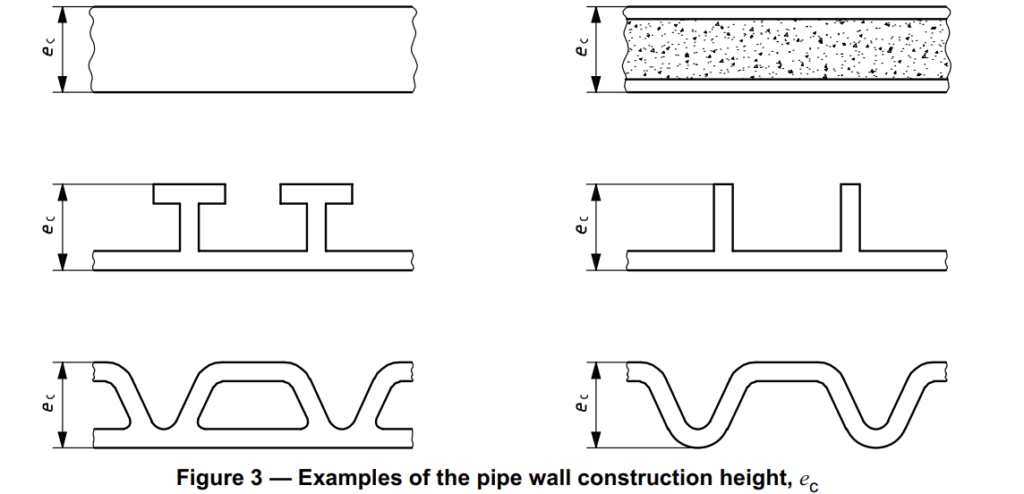
displacement of one of the flat plates, but if during the test the pipe wall construction height, ec (see Figure 3),
changes by more than 5 %, generate the force/deflection plot by measuring the change of the inside diameter of the test piece.
In case of dispute, the change of the inside diameter shall be used as a reference.
If the force versus deflection plot, which is typically a smooth curve, indicates that the zero point may be in error, as shown in Figure 4, extrapolate back the initial straight line portion of the curve and use the intersect with the horizontal axis as the (0,0) point (origin).
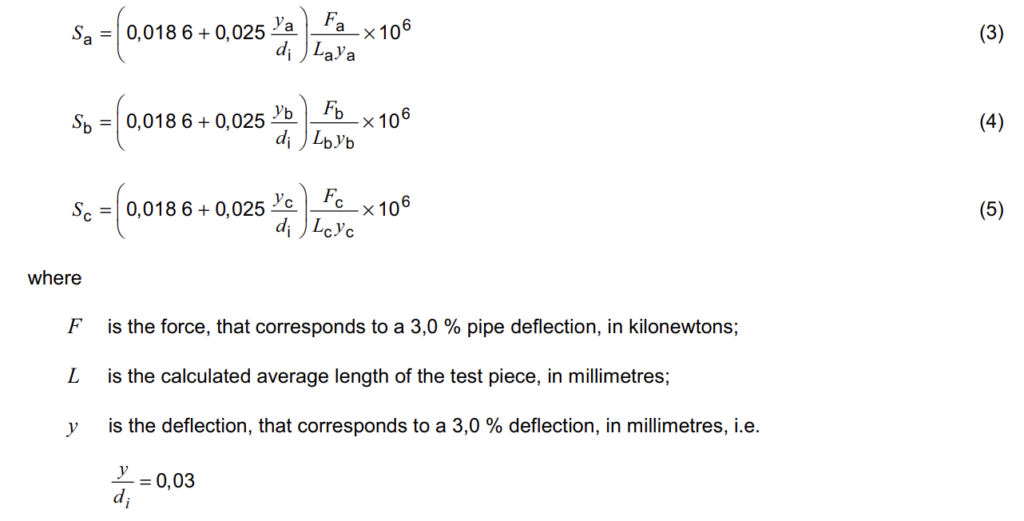
9 Calculation of ring stiffness
Calculate the ring stiffness, Sa, Sb and Sc, of each of the three test pieces (a, b and c, respectively), in
kilonewtons per square metre, using the following equations:
Calculate the ring stiffness of the pipe, S, in kilonewtons per square meter, as the average of these three
values, using Equation (6):


