

User Manual and Test Procedure – ISO 18553
The AHP PLASTIK MAKINA Carbon Black Dispersion Tester is designed for the microscopic examination and assessment of the degree of carbon black or pigment dispersion in polyolefin materials.
The system is particularly suitable for quality control and laboratory testing of polyethylene (PE) raw materials, compounds, pipes, fittings, and other applicable polyolefin products.
Carbon black is commonly incorporated into polyethylene materials to provide coloration and protection against degradation caused by ultraviolet radiation. Proper dispersion of carbon black within the polymer matrix is therefore important for maintaining the physical, mechanical, and surface protection properties of the final product.
The AHP testing system combines microscopic examination, digital image acquisition, calibrated dimensional measurement, automatic image analysis, grading, and test reporting in one complete laboratory system.
1. Applicable Standard
The principal applicable standard is:
ISO 18553 – Method for the assessment of the degree of pigment or carbon black dispersion in polyolefin pipes, fittings and compounds
ISO 18553 describes two procedures for assessing the size of pigment or carbon black particles and agglomerates and the degree of their dispersion in polyolefin materials.
The method is applicable to:
- Polyolefin pipes
- Polyolefin fittings
- Polyolefin compounds
- Raw materials in pellet form
- Carbon-black-pigmented polyolefins containing less than 3% carbon black
The appropriate specimen preparation procedure should be selected according to the applicable product specification.
2. Principle of the Test
Small specimens are obtained from the raw material or removed from the finished pipe, fitting, or other applicable product.
ISO 18553 specifies two alternative methods for specimen preparation:
Method 1 – Compression Procedure
Small pieces of the material are placed between microscope slides, heated, and compressed to produce thin films suitable for microscopic examination.
Method 2 – Microtome Procedure
Thin sections are cut directly from the material or finished product using a suitable microtome.
After specimen preparation, six specimens are examined microscopically.
The particles and agglomerates visible in each specimen are evaluated and their largest dimensions are measured.
The particle/agglomerate size grading for the complete sample is determined from the individual grades obtained from the six specimens.
When required, the appearance of the dispersion can also be evaluated by comparison with the reference photomicrographs specified in ISO 18553.
3. AHP Carbon Black Dispersion Testing System
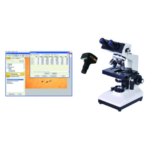
The AHP PLASTIK MAKINA Carbon Black Dispersion Testing System provides the equipment required for microscopic examination, digital image acquisition, measurement, and analysis of carbon black dispersion.
Main Components
The system may include:
- Optical microscope
- Digital microscope camera
- Microscope illumination system
- AHP Carbon Black Dispersion Analysis Software
- Computer connection interface
- Calibration glass slide
- Microscope glass slides
- Cover slips
- Sample preparation accessories
- Sample cutter
- Microtome, depending on the ordered configuration
- Compression sample preparation accessories, depending on the ordered configuration
The software is designed to assist the operator in processing microscopic images and evaluating the particle and agglomerate distribution of the specimens.
4. Specimen Preparation
Correct specimen preparation is one of the most important stages of the carbon black dispersion test.
The specimen must be sufficiently thin and uniform to allow the carbon black particles and agglomerates to be clearly observed under transmitted light.
ISO 18553 defines two specimen preparation procedures:
- Microtome Procedure
- Compression Procedure
Six specimens shall be prepared from different parts of the material being evaluated.
5. Microtome Specimen Preparation
5.1 Sampling from Finished PE Products
For testing finished products such as PE100 pipes and fittings, cut a small piece from the finished product.
The sample should have dimensions suitable for secure installation in the specimen holder of the microtome. Samples should be obtained from different areas of the product to provide representative specimens. Where practical, specimens should be taken along different axes of the product.
Prepare a total of six specimens from different parts of the product.
5.2 Installing the Sample in the Microtome
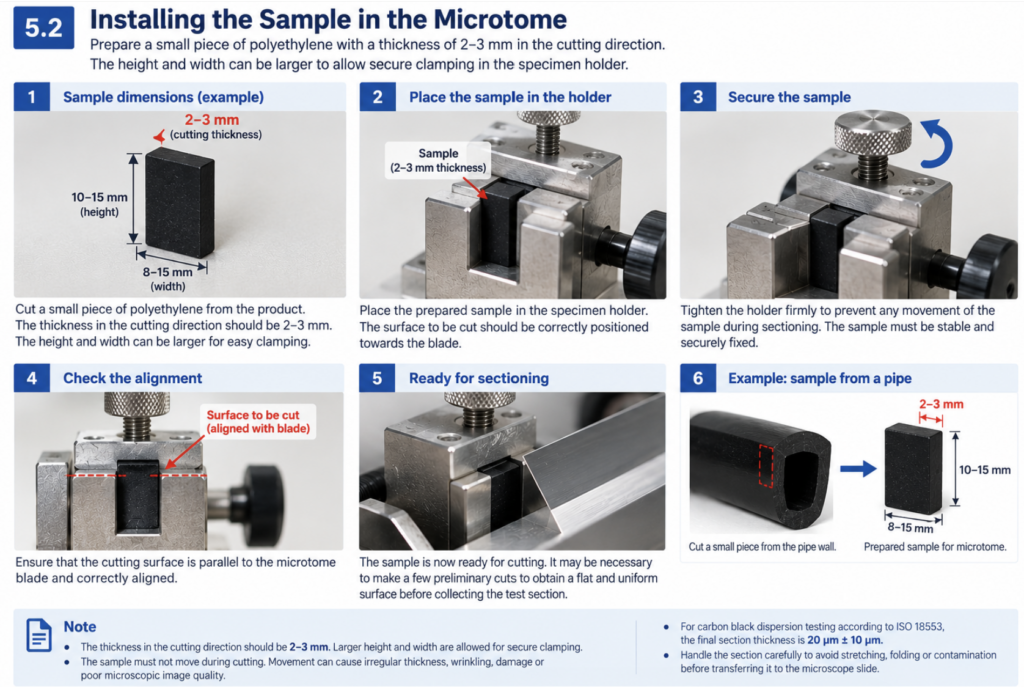
Place the prepared piece of polyethylene in the microtome specimen holder.
Secure the sample firmly.
The sample must not move during the cutting operation. Movement of the sample can cause:
- Irregular section thickness
- Wrinkled sections
- Damaged sections
- Non-parallel cutting
- Poor microscopic image quality
Position the surface to be cut correctly relative to the microtome blade.
5.3 Preparing a Pellet for Microtome Cutting
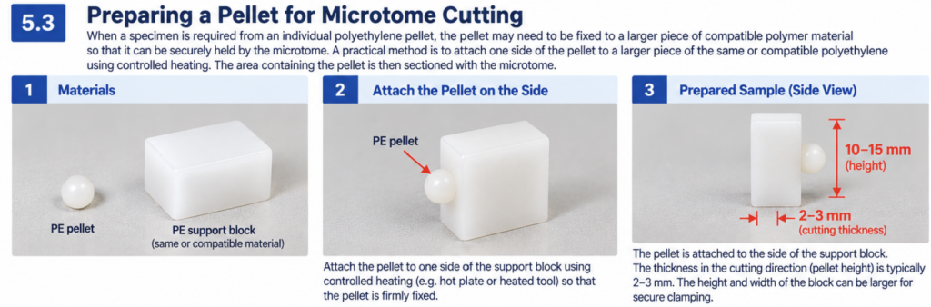
When a specimen is required from an individual polyethylene pellet, the pellet may need to be fixed to a larger piece of compatible polymer material so that it can be securely held by the microtome.
A practical preparation method is to attach one side of the pellet to a larger piece of the same or compatible polyethylene material using controlled heating.
The larger supporting piece can then be secured in the microtome specimen holder.
The area containing the pellet is subsequently sectioned with the microtome.
Care should be taken not to excessively heat or otherwise alter the area of the pellet that will be evaluated.
5.4 Microtome Cutting Thickness
Adjust the microtome to produce the required section thickness.
For Carbon Black Dispersion
Required thickness: 20 µm ± 10 µm
For Pigment Dispersion
Required thickness: 60 µm ± 20 µm
Each microtome specimen should also be at least 4 mm across in any direction.
5.5 Transferring the Section to the Microscope Slide
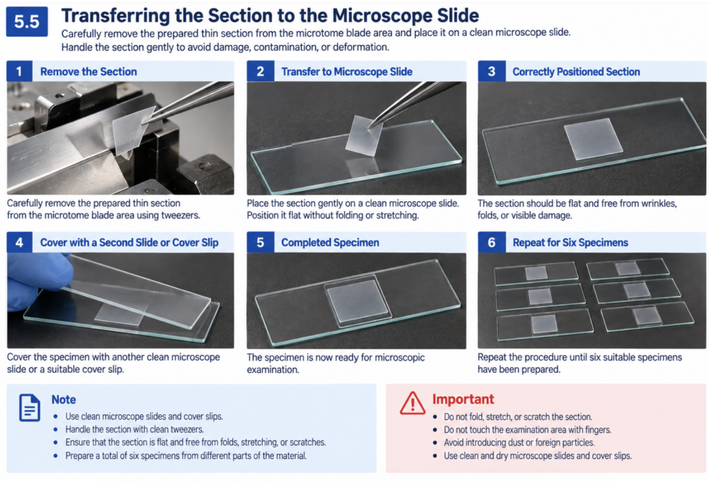
Carefully remove the prepared thin section from the microtome blade area.
Place the specimen on a clean microscope slide.
Avoid:
- Folding the specimen
- Stretching the specimen
- Scratching the specimen
- Touching the examination area with fingers
- Introducing dust or foreign particles
Cover the specimen with another clean microscope slide or a suitable cover slip.
Repeat the procedure until six suitable specimens have been prepared.
6. Compression Specimen Preparation
The compression procedure is an alternative to microtome sectioning.
6.1 Cutting the Specimens
Using a clean scalpel or suitable cutting tool, cut six specimens from different parts of the material.
For Carbon Black Dispersion
Mass of each specimen: 0.20 mg ± 0.10 mg
For Pigment Dispersion
Mass of each specimen: 0.6 mg ± 0.2 mg
The specimens should preferably be obtained from different positions and, where appropriate, different axes of the product.
6.2 Positioning the Specimens
Place the six specimens on one or more clean microscope slides.
Position the specimens approximately equidistant from:
- Each other
- The edges of the microscope slide
Cover the specimens using another clean microscope slide or suitable cover slips.
Suitable shims may be used to help obtain a uniform final film thickness.
6.3 Heating and Compression
Heat the specimens at a controlled temperature between: 150°C and 210°C
When an oven and spring clips are used, clamp the microscope slides together and place them in the oven.
Maintain the slides at the selected temperature for at least 10 minutes, until the specimens have been pressed into films of the required thickness.
Alternatively, the slides may be placed on a suitable hotplate or other controlled heating device and pressure applied using a press or suitable weight.
Required Final Thickness
Carbon Black Dispersion: 20 µm ± 10 µm
Pigment Dispersion: 60 µm ± 20 µm
After compression, allow the slides to cool before microscopic examination.
7. Microscope Setup
Place the microscope on a clean, stable, and vibration-free laboratory table.
Avoid installing the microscope in locations exposed to:
- Excessive vibration
- Dust
- Direct sunlight
- High humidity
- Significant temperature fluctuations
Connect the digital camera to the microscope.
Connect the camera to the computer.
Switch on the microscope illumination system.
Start the computer and the AHP Carbon Black Dispersion Analysis Software.
Verify that a live microscope image is visible on the computer screen.
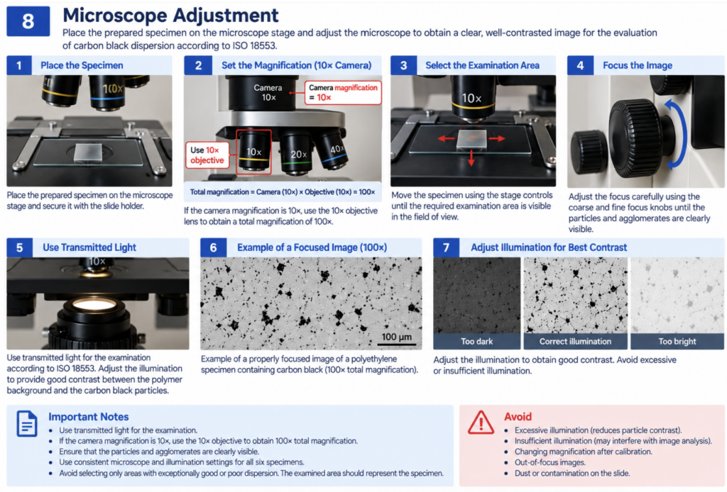
8. Microscope Adjustment
Place the prepared specimen on the microscope stage.
Move the specimen until the required examination area is visible. Adjust the microscope focus carefully until the boundaries of the particles and agglomerates are clearly visible.
For the assessment of the degree of dispersion according to ISO 18553, specimens are examined under transmitted light.
Recommended Magnification
100×
The illumination should provide sufficient contrast between the polymer background and the carbon black particles.
Avoid excessive illumination because excessive brightness can reduce particle contrast.
Avoid insufficient illumination because dark background areas may interfere with digital image analysis.
For consistent results, use the same optical and illumination settings for all six specimens.
9. AHP Carbon Black Dispersion Analysis Software
The AHP Carbon Black Dispersion Analysis Software is designed to assist the operator in evaluating microscopic images of prepared specimens.
The software allows the operator to:
- Display microscope images
- Capture specimen images
- Calibrate dimensional measurements
- Load specimen images
- Analyze particles and agglomerates
- Measure particle/agglomerate dimensions
- Evaluate multiple specimens
- Determine dispersion results
- Store test information
- Prepare test reports
For a complete ISO 18553 evaluation, images from six specimens are used.




Analysis Software for Dispersion Tester according to ISO 18553
1- Define Sample general parameters

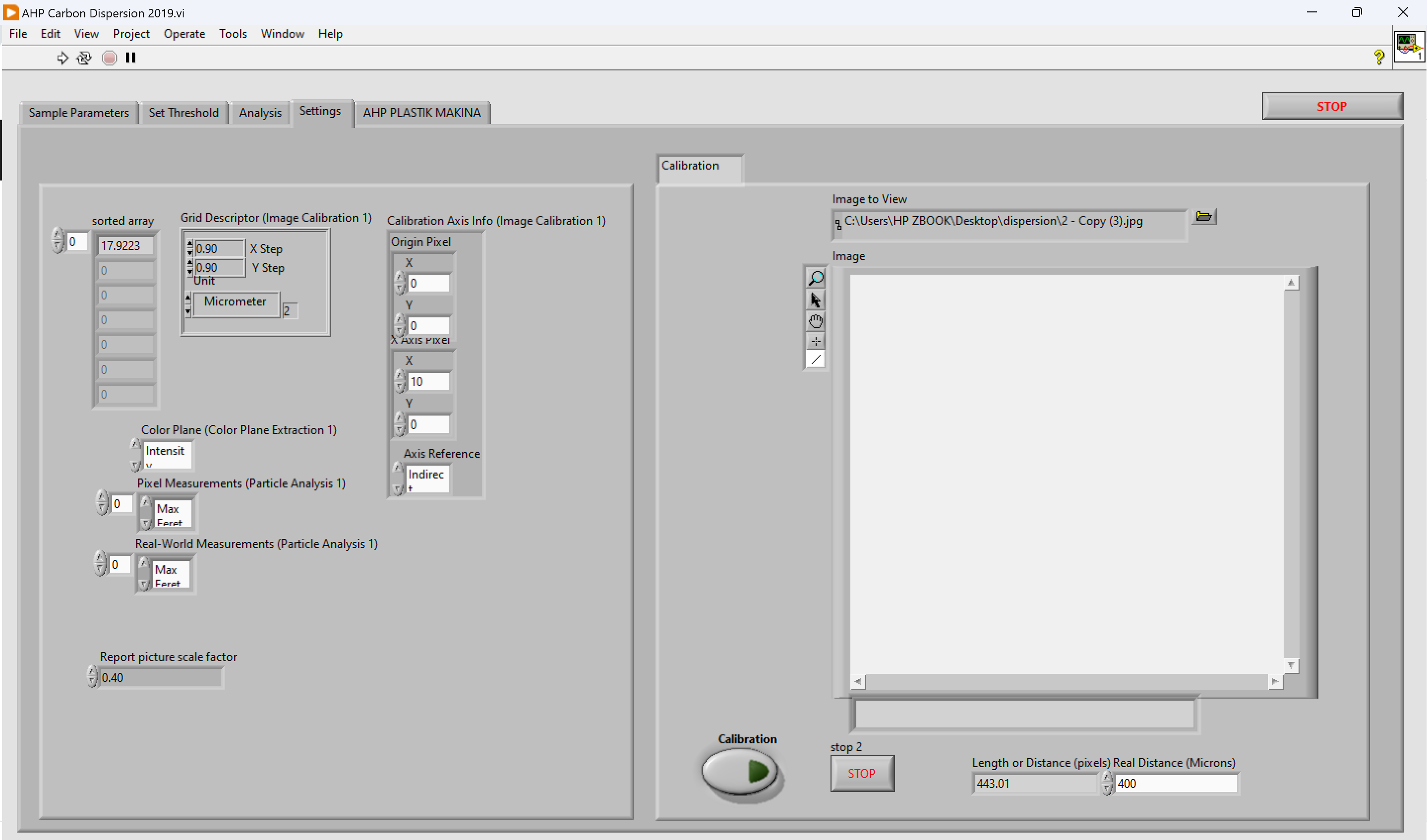
2- Calibrate the microscope 100X pictures (will be done only for first run of machine)
Any microscope from any brands can be used for this test. Software is suitable for all brands.
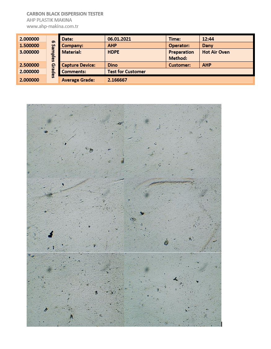
3- Load 6 captured pictures from samples

4- Analysis will be done automatically according to ISO 18553 (table according to Annex A)
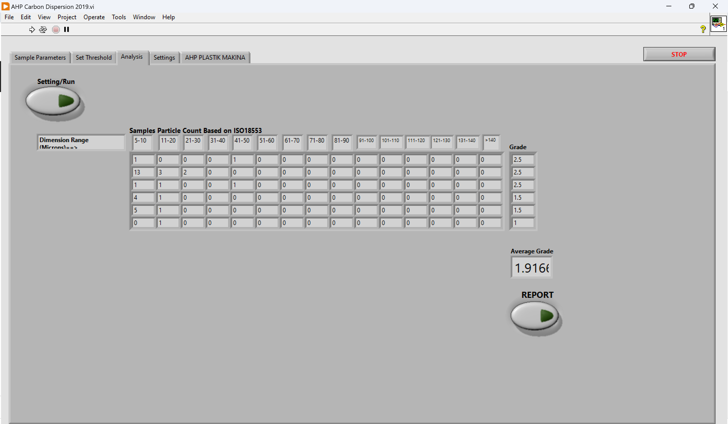
5- At the end will give you a report including original captured pictures and analysis results in single MS-WORD page
6- For any detailed info please contact to our sales.
10. Software Calibration
Before quantitative measurement, the image measurement system must be calibrated.
Calibration establishes the relationship between the pixels in the digital microscope image and the actual dimensions in micrometers.
Calibration Procedure
- Place the supplied calibrated glass slide on the microscope stage.
- Select the microscope magnification that will be used for the test.
- Adjust the focus until the calibration scale is clearly visible.
- Open the calibration function in the AHP software.
- Select the required reference points on the calibration scale.
- Enter the actual known distance between the selected calibration points.
- Confirm and save the calibration.
After calibration, the software can convert distances measured in the digital image into actual dimensions in micrometers (µm).
Important
Calibration should be checked or repeated whenever a change is made that can affect the image scale, including:
- Microscope magnification
- Camera configuration
- Camera resolution
- Optical configuration
Do not perform dimensional analysis using an incorrect calibration.
11. Test Procedure
Step 1 – Prepare Six Specimens
Prepare six specimens using either: Microtome Procedure
or
Compression Procedure
Make sure that all specimens meet the required preparation conditions.
Step 2 – Place the First Specimen Under the Microscope
Place Specimen 1 on the microscope stage.
Use transmitted illumination.
Set the required magnification.
Adjust the microscope focus until a clear image is obtained.
Step 3 – Select the Examination Area
Move the microscope stage to select an appropriate examination area.
The selected area should represent the specimen.
Do not intentionally select only areas showing exceptionally good or exceptionally poor dispersion.
Step 4 – Capture the Image
Capture a clear digital image using the microscope camera and AHP software.
Save or assign the image as:
Specimen 1
Step 5 – Repeat for All Six Specimens
Repeat the same procedure for:
Specimen 2
Specimen 3
Specimen 4
Specimen 5
Specimen 6
Use consistent magnification, illumination, focus quality, and calibration throughout the test.
12. Particle and Agglomerate Measurement
For assessment of the degree of dispersion, examine the particles and agglomerates in each of the six specimens.
The largest dimension of each relevant particle or agglomerate is measured.
According to ISO 18553, particles and agglomerates with dimensions below: 5 µm
are ignored for grading purposes.
13. ISO 18553 Particle Size Categories
Particles and agglomerates are classified according to their largest dimensions.
The size categories used in the ISO 18553 grading system are:
| Particle / Agglomerate Size |
|---|
| 5 to 10 µm |
| 11 to 20 µm |
| 21 to 30 µm |
| 31 to 40 µm |
| 41 to 50 µm |
| 51 to 60 µm |
| 61 to 70 µm |
| 71 to 80 µm |
| 81 to 90 µm |
| 91 to 100 µm |
| 101 to 110 µm |
| 111 to 120 µm |
| 121 to 130 µm |
| 131 to 140 µm |
| Greater than 140 µm |
The AHP software assists the operator in evaluating the detected particles and agglomerates according to their measured dimensions.
14. Grading of Each Specimen
Each specimen is evaluated individually.
The particle and agglomerate size distribution is evaluated according to the grading table specified in Annex A of ISO 18553.
The grading scale ranges from: Grade 0 to Grade 7
with intermediate increments of 0.5.
The highest applicable particle/agglomerate size grade is determined for each specimen.
At the end of the analysis, six individual grades are available:
- Grade of Specimen 1
- Grade of Specimen 2
- Grade of Specimen 3
- Grade of Specimen 4
- Grade of Specimen 5
- Grade of Specimen 6
15. Calculation of the Final Dispersion Grade
The arithmetic mean of the six individual specimen grades is calculated.
Average Grade = (G1 + G2 + G3 + G4 + G5 + G6) / 6
The result is expressed to one decimal place and rounded upward to the next higher value as specified by ISO 18553.
Calculation Example
Assume the following individual grades:
| Specimen | Grade |
|---|---|
| Specimen 1 | 2.0 |
| Specimen 2 | 2.5 |
| Specimen 3 | 3.0 |
| Specimen 4 | 2.5 |
| Specimen 5 | 3.0 |
| Specimen 6 | 3.5 |
Arithmetic mean:
(2.0 + 2.5 + 3.0 + 2.5 + 3.0 + 3.5) / 6 = 2.75
Final reported result: Grade 2.8
This example follows the calculation example provided in ISO 18553.
16. Appearance Rating
When required by the applicable product specification, an additional appearance rating can be performed.
Examine each specimen under transmitted light at a magnification of at least: 70×
Compare the appearance of each specimen with the reference photomicrographs given in Annex B of ISO 18553.
Record:
- Appearance of each individual specimen
- Dominant appearance of the complete set of specimens
The appearance rating is separate from the numerical particle/agglomerate size grade.
17. Recommended Basic Acceptance Criteria
Annex D of ISO 18553 provides an informative basic specification.
The recommended mean grading limit is: Mean Grade ≤ 3
For appearance rating, the recommended result is: Not worse than Photomicrograph B
Therefore, under the basic specification in Annex D, the acceptable appearance ratings are: A1, A2, A3, and B.
Important: Annex D is informative. The actual acceptance criteria shall be determined by the applicable product standard, customer specification, contractual requirement, or internal quality-control specification.
18. Test Report
The test report should provide sufficient information to identify the tested material, specimen preparation method, test conditions, and obtained results.
According to ISO 18553, the report should include:
- Complete identification of the tested material or product
- Sample type
- Sample origin
- Manufacturer’s code or identification, where applicable
- Relevant previous history of the sample
- Reference to ISO 18553
- Specimen preparation method: Compression or Microtome
- Specimen thickness
- Individual grades of the six specimens
- Average grade
- Individual appearance ratings, when required
- Dominant appearance rating, when required
- Any deviation from the specified test method
- Any incident that may have influenced the result
- Date of the test
These reporting requirements are specified in Clause 6 of ISO 18553.
19. Important Testing Precautions
Specimen Thickness
Correct specimen thickness is essential for reliable microscopic examination.
A specimen that is too thick may make it difficult to distinguish individual particles and agglomerates.
Cleanliness
Always use clean:
- Microscope slides
- Cover slips
- Cutting tools
- Microtome blades
- Working surfaces
Foreign contamination can be incorrectly interpreted as particles.
Microtome Blade
The blade should be sufficiently sharp to produce a uniform section.
A damaged or blunt blade may cause:
- Uneven section thickness
- Surface damage
- Folding
- Tearing
- Distortion of the specimen
Microscope Calibration
Always verify that the correct calibration is active before measuring particle dimensions.
If the magnification or optical configuration is changed, calibration must be checked again.
Illumination
Use consistent transmitted illumination during examination of all six specimens.
Excessive or insufficient illumination can affect image quality and digital particle detection.
20. Routine Maintenance
Keep the microscope and camera clean and protected from dust.
Clean optical surfaces only with suitable optical cleaning materials.
Do not use abrasive materials or aggressive solvents on microscope lenses.
Store the calibration glass slide in its protective case.
Protect the calibration scale from scratches and contamination.
Keep microscope slides and cover slips in a clean, dry location.
Check the microtome blade regularly and replace or service it when section quality deteriorates.
Periodically verify dimensional calibration using the supplied calibration slide.
Back up important test images and reports.
21. Troubleshooting
No Image from the Microscope Camera
- Check the camera connection.
- Check the USB or communication cable.
- Confirm that the camera is recognized by Windows.
- Close and restart the AHP software if necessary.
Microscope Image Is Too Dark
- Increase illumination.
- Check the microscope light source.
- Check the position of the specimen.
- Verify that the optical path is correctly adjusted.
Microscope Image Is Too Bright
- Reduce illumination intensity.
- Adjust the microscope light control.
- Check camera exposure settings if applicable.
Particle Edges Are Not Clear
- Adjust microscope focus.
- Check specimen thickness.
- Clean the microscope optics.
- Clean the microscope slide.
- Check whether the specimen is folded or damaged.
Measured Dimensions Appear Incorrect
- Check the active calibration.
- Confirm that microscope magnification has not been changed.
- Check the camera configuration.
- Repeat calibration using the calibration glass slide.
Microtome Section Is Irregular
- Check the microtome blade.
- Make sure the sample is securely fixed.
- Check the selected cutting thickness.
- Verify that the sample does not move during cutting.
22. Safety Instructions
Only trained laboratory personnel should operate the equipment.
Microtome Safety
The microtome blade is extremely sharp.
Keep hands and fingers away from the cutting edge.
Use appropriate precautions when:
- Installing the blade
- Removing the blade
- Cleaning the blade
- Replacing the blade
- Removing specimens near the cutting area
Hot Surface Safety
When the compression procedure is used, the heating equipment and microscope slides may reach temperatures between 150°C and 210°C.
Use appropriate heat-resistant gloves or handling tools.
Allow heated microscope slides to cool sufficiently before handling.
Electrical Safety
Keep liquids away from:
- Microscope electrical components
- Digital camera
- Computer
- Cables and connectors
Do not operate electrical equipment with damaged cables or connectors.
23. Storage
When the equipment is not in use:
- Switch off the microscope illumination.
- Close the AHP software correctly.
- Switch off the computer when appropriate.
- Cover the microscope to protect it from dust.
- Store the calibration slide in its protective case.
- Keep microscope slides and cover slips clean and dry.
- Protect the microtome blade from accidental contact and corrosion.
24. Quick Reference – ISO 18553 Test Conditions
| Parameter | Requirement |
|---|---|
| Number of specimens | 6 |
| Carbon black specimen thickness | 20 µm ± 10 µm |
| Pigment specimen thickness | 60 µm ± 20 µm |
| Minimum microtome specimen dimension | At least 4 mm across in any direction |
| Recommended magnification for grading | 100× |
| Minimum magnification for appearance rating | 70× |
| Minimum particle size considered for grading | 5 µm |
| Compression temperature | 150°C to 210°C |
| Carbon black specimen mass – Compression | 0.20 mg ± 0.10 mg |
| Pigment specimen mass – Compression | 0.6 mg ± 0.2 mg |
| Number of individual grades | 6 |
| Final result | Arithmetic mean of six grades |
| Recommended basic mean grade | ≤ 3 |
25. Manufacturer
AHP PLASTIK MAKINA
Manufacturer of Plastic and Polymer Laboratory Testing Equipment
For technical support, software assistance, spare parts, calibration support, and further information, please contact AHP PLASTIK MAKINA.