
Introduction
ASTM F2136 – Notched, Constant Ligament-Stress (NCLS) Test to Determine Slow-Crack-Growth Resistance of HDPE Resins or HDPE Corrugated Pipe is a laboratory test method developed to evaluate the resistance of high-density polyethylene materials to Slow Crack Growth (SCG).
Slow crack growth is one of the most important long-term failure mechanisms in polyethylene products subjected to sustained mechanical stress.
Unlike conventional tensile testing, where the specimen is loaded relatively quickly until yielding or rupture, the NCLS test subjects a specially prepared and notched polyethylene specimen to a constant ligament stress while the specimen is immersed in a surface-active solution at elevated temperature.
The time required for the specimen to fail is measured. The final result is therefore principally expressed as:
NCLS Failure Time – hours
or as the arithmetic average failure time of a group of specimens. The longer the failure time under identical test conditions, the greater the resistance of the polyethylene material to slow crack growth.
1. Purpose of ASTM F2136
The primary purpose of ASTM F2136 is to determine the susceptibility of HDPE materials to slow crack growth under accelerated laboratory conditions.
The test can be used for:
- Virgin HDPE resin
- Compression-moulded HDPE plaques
- Material recovered from HDPE corrugated pipe
- Comparison between different HDPE compounds
- Evaluation of resin formulation
- Product qualification where another specification refers to ASTM F2136
- Research and development
- Quality-control investigations
The method measures: Time to Failure under a Specified Constant Ligament Stress
The test does not directly reproduce decades of field service.
Instead, three accelerating mechanisms are used simultaneously:
- A sharp controlled notch
- Elevated temperature
- A surface-active chemical environment
These conditions accelerate crack initiation and propagation so differences between polyethylene materials can be evaluated within a practical laboratory period.
2. Principle of the NCLS Test
A dumbbell-shaped polyethylene specimen is prepared with a carefully controlled notch across its reduced section. The specimen is mounted in a loading frame and submerged in a heated surfactant solution. A constant tensile load is then applied.
However, ASTM F2136 differs from ordinary constant-load testing because the load is calculated according to the remaining ligament area below the notch.
The critical stress is therefore: Ligament Stress
rather than nominal stress calculated from the original unnotched section.
The effective remaining area is:
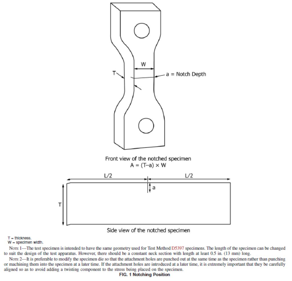
A = (T − a) × W
where:
- A = remaining ligament cross-sectional area
- T = measured specimen thickness
- a = measured notch depth
- W = specimen reduced-section width
The required tensile force is then based upon:
F = S × (T − a) × W
where:
- F = required tensile force
- S = specified ligament stress
The specimen remains under this loading condition until complete failure occurs.
3. Why the Notch Is Important
Slow crack growth is highly sensitive to local stress concentration. For this reason, ASTM F2136 introduces a precisely controlled notch into the specimen.
The notch:
- Creates a reproducible stress concentration
- Defines the crack initiation location
- Accelerates slow crack propagation
- Reduces variability associated with random crack initiation
- Allows different HDPE materials to be compared under standardized conditions
The notch geometry is therefore one of the most critical parts of the entire test.
A small error in notch depth changes the remaining ligament thickness and consequently changes the actual stress acting on the ligament.
For this reason, notch depth must be measured individually for each specimen.
4. Main NCLS Testing Equipment
A complete ASTM F2136 testing system requires several pieces of equipment.
The principal components are:
- NCLS constant-load testing frame
- Lever-arm loading stations or equivalent constant-load system
- Heated liquid bath
- Temperature controller
- Specimen grips
- Weight tubes
- Metal shot or calibrated dead weights
- Notching device
- Razor blades
- Microscope with dimensional measurement capability
- Precision micrometer
- Electronic balance
- Specimen blanking die
- Compression moulding press
- Compression moulding chase
- Accurate timing system
Each component influences the reliability of the test.
5. Stress-Crack Testing Apparatus
The traditional ASTM F2136 apparatus uses a: Lever-Arm Constant-Load System
The lever ratio should typically be between: 2:1 and 5:1
A mechanical advantage produced by the lever allows a relatively small dead weight to generate the required tensile force on the specimen.
Alternatively, ASTM F2136 permits the tensile force to be applied directly using:
- Dead weights
- Other mechanical loading systems
- Any suitable method capable of maintaining the required constant ligament stress
The critical requirement is not the exact mechanical arrangement.
The system must maintain the calculated specimen load with adequate accuracy throughout the test.
6. Independent Test Stations
A practical NCLS tester normally contains several independent test positions.
ASTM F2136 requires:
Five specimens at one ligament-stress level
for each test set.
Therefore, a laboratory instrument should provide at least five simultaneous loading stations for efficient testing.
Larger instruments may include:
- 5 stations
- 10 stations
- 20 stations
- 30 stations
- More than 30 stations
Each station should preferably have its own:
- Loading lever
- Specimen grip
- Weight attachment point
- Timer
- Failure detection mechanism
Independent stations are beneficial because each specimen can fail at a different time.
7. Calibration of Each Loading Station
Each test station must be individually verified.
The standard requires determination of:
- Zero-load offset
- Lever-arm ratio
for each loading station.
A calibrated force standard complying with ASTM E4 principles is used. The load applied to the specimen must be accurate within:
±0.5% of the calculated or applied load
This is a very important equipment requirement. It means that simply designing every lever with identical nominal dimensions is not sufficient. Each station should be calibrated individually because small differences can occur due to:
- Lever geometry
- Pivot friction
- Lever self-weight
- Manufacturing tolerances
- Attachment position
- Bearing friction
For high-quality NCLS equipment, each station should therefore have its own calibrated mechanical advantage and correction factor.
8. Heated Test Bath
All specimens are tested while immersed in a heated chemical solution.
The required bath temperature is: 50 ± 1 °C
equivalent to: 122 ± 2 °F
The bath should therefore include:
- Heating elements
- Temperature sensor
- Closed-loop temperature controller
- Adequate liquid circulation
- Insulated bath construction
- Specimen-support structure
- Sufficient liquid volume
Temperature uniformity is particularly important because polyethylene slow crack growth is strongly temperature-dependent.
A specimen located in a warmer region of the bath can fail significantly earlier than an identical specimen located in a colder region.
9. Temperature Control Requirements
The test solution must remain at: 50 ± 1 °C
throughout testing. The temperature-control system should therefore maintain all specimen locations within the permitted range.
Recommended equipment design features include:
- PID temperature controller
- PT100 or equivalent temperature sensor
- Liquid circulation pump
- Over-temperature protection
- Independent temperature display
For long-duration tests, continuous temperature recording is also advantageous.
10. NCLS Test Solution
ASTM F2136 specifies a surface-active stress-cracking reagent consisting of: 10% nonylphenoxy poly(ethyleneoxy) ethanol
and: 90% deionized water
by volume.
The surfactant specified in the edition supplied is: Igepal CO-630 or equivalent
The purpose of the surfactant is to accelerate environmentally assisted slow crack propagation.
The bath solution level must be checked: Daily
Any liquid loss is compensated by adding: Deionized water
to restore the original bath level. This point is important because water evaporation can gradually increase surfactant concentration if the bath level is allowed to fall.
11. Why Deionized Water Is Used
Deionized water minimizes uncontrolled contamination of the bath solution. Water containing minerals or dissolved ions could potentially change:
- Chemical environment
- Surface interactions
- Long-term bath composition
- Test reproducibility
For this reason, bath makeup should be performed using deionized water rather than ordinary tap water.
12. Specimen Blanking Die
Test specimens are cut using an appropriate blanking die. ASTM F2136 permits:
- Type L die according to ASTM D1822, with suitable attachment holes
- A die manufactured according to the dimensions specified by ASTM F2136
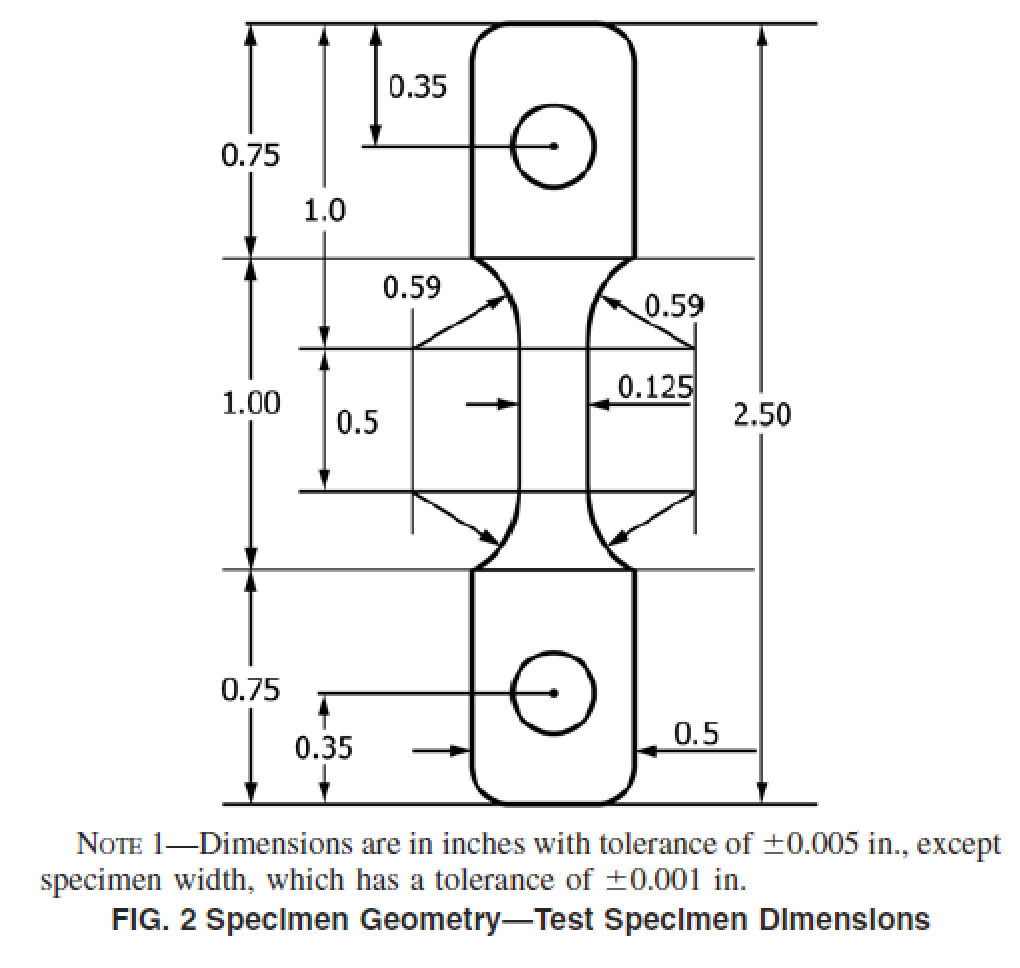
The specimen has a dumbbell-type geometry with a narrow central reduced section.
The die should produce:
- Smooth edges
- Consistent width
- Correct transition radii
- Correct specimen length
- Repeatable geometry
Damaged or rough specimen edges can create additional crack-initiation locations and invalidate the test.
13. Specimen Attachment Holes
The specimen contains attachment holes at both enlarged ends.
Whenever possible, the holes should be produced simultaneously during die cutting. If the holes are drilled or punched later, they must be accurately aligned.
Misaligned attachment holes can introduce:
- Specimen twisting
- Bending
- Uneven tensile stress
- Premature failure
The load axis should pass centrally through the specimen.
14. Specimen Geometry
The principal specimen dimensions specified in ASTM F2136 are:
Total Length
60.00 ± 0.25 mm
Reduced Section Width
3.20 ± 0.02 mm
Thickness
1.90 ± 0.08 mm
The reduced section should contain a constant-width neck region.
The standard notes that the specimen length may be modified to suit the testing machine, provided an adequate constant neck section is maintained.
A constant reduced section of at least approximately: 13 mm
is required.
15. Acceptance of Specimen Dimensions
Before a specimen is accepted for testing, its geometry should satisfy the applicable tolerances.
Nominal dimensions:
Length = 60.00 ± 0.25 mm
Width = 3.20 ± 0.02 mm
Thickness = 1.90 ± 0.08 mm
A specimen outside the dimensional tolerances should not be treated as a standard ASTM F2136 specimen.
Particular attention should be paid to reduced-section width because its tolerance is relatively tight.
16. Preparation of Virgin Resin Plaques
For virgin resin testing, HDPE pellets are compression moulded into sheet.
The nominal sheet thickness is: 1.9 mm
The plaque is prepared according to the applicable compression-moulding procedure referenced by ASTM F2136.
The pellets do not necessarily require roll milling before compression moulding according to the method described in this edition.
After moulding, specimens are die-cut from the plaque.
17. Preparation of Specimens from Corrugated Pipe
Testing actual pipe material requires additional preparation.
Directly cutting a tensile specimen from an extruded pipe wall is not appropriate for this method because extrusion introduces molecular orientation.
This orientation can substantially influence slow crack growth results.
ASTM F2136 therefore requires the pipe material to be:
- Cut from the pipe
- Chopped into small pieces
- Randomized
- Compression moulded into a plaque
- Die-cut into test specimens
This procedure reduces the effect of extrusion-induced orientation.
18. Sampling from Corrugated Pipe
Approximately: 25 mm wide
sections are cut from the pipe along its longitudinal axis.
These sections are then chopped into smaller pieces.
Approximately: 0.5 kg
of representative material is collected.
The sample should represent a complete cross-section from: Inside surface → Outside surface
of the pipe wall.
The chopped material is subsequently compression moulded into a plaque.
19. Dual-Wall Pipe Materials
If different polyethylene materials are used for:
- Inner wall
- Outer wall
of a dual-wall corrugated pipe, ASTM F2136 requires the materials to be:
Tested separately
The test result should therefore not be based on a mixed plaque if the two walls contain different compounds.
20. Avoiding Plaque Edge Effects
The standard permits trimming approximately: 15 mm
from each side of a moulded sheet where desired.
This can help eliminate edge effects associated with compression moulding.
Specimens should preferably be obtained from uniform areas of the plaque.
21. Notching Device
The specimen notch is produced using a controlled notching device.
Notch depth is one of the most critical test variables.
The approximate blade thickness specified is: 0.2 to 0.3 mm
A suitable device should provide:
- Controlled vertical movement
- Stable specimen holding
- Controlled cutting speed
- Repeatable blade position
- Accurate depth control
- Minimal bending of the specimen
A manually uncontrolled cut is not recommended for precise NCLS testing.
22. Razor Blade Requirements
Several suitable steel razor-blade configurations may be used.
The critical requirements are:
- Blade sharpness
- Controlled thickness
- Clean cutting edge
- Consistent notch geometry
A single razor blade must not be used for more than: 10 test specimens
After ten specimens, the blade should be replaced.
Blade wear can produce a rounded or irregular notch tip and significantly influence crack initiation.
23. Location of the Notch
The specimen is notched across the centre of its reduced section.
The notch must be:
- Perpendicular to the plane defined by specimen length and width
- At right angles to the applied loading direction
- Centrally positioned in the reduced section
Incorrect notch orientation can produce mixed-mode stresses and invalidate comparison with standard test results.
24. Notching Speed
The notch must be produced at a maximum cutting rate of: 2.5 mm/min
or: 0.1 in/min
A controlled, slow cutting action is necessary to obtain consistent notch geometry without excessive local deformation.
25. Notch Depth
The required notch depth is calculated from:
a = 0.20 × T
where:
- a = notch depth
- T = measured specimen thickness
Therefore, the notch removes: 20% of the specimen thickness
and leaves a ligament thickness of approximately: 80% of the original thickness
For a nominal specimen thickness of: 1.90 mm
the approximate nominal notch depth is:
a = 0.20 × 1.90
a ≈ 0.38 mm
The actual value must be calculated using the measured thickness of the individual specimen.
26. Notch Depth Tolerance
Notch depth must be controlled within: ±0.025 mm
or: ±0.001 in
This tight tolerance demonstrates why a precision notch cutter and microscope are essential.
Visual estimation of notch depth is not adequate.
27. Measurement of Notch Depth
The notch depth is measured using: Microscope equipped with a micrometer
or an equivalent dimensional measurement system.
The device must be capable of accurately measuring the small notch depth.
Alternative modern systems may use:
- Measuring microscope
- Digital microscope with calibrated software
- Optical measuring system
provided measurement accuracy is sufficient.
28. Precision Micrometer
A micrometer is required for measuring specimen dimensions.
Required capability: ±0.025 mm
approximately: ±0.001 in
The following dimensions are measured:
- Reduced-section width
- Specimen thickness
These measured values are used directly in calculating the load for each individual specimen.
29. Individual Measurement of Every Specimen
Load should not simply be calculated from nominal specimen dimensions.
For every specimen, measure:
W = Reduced section width
T = Thickness
a = Notch depth
The remaining ligament thickness is: T − a
The ligament area is: A = (T − a) × W
This individual measurement is necessary because even small dimensional variations alter the effective stress.
30. Constant Ligament Stress
The defining characteristic of the NCLS method is the use of:
Constant Ligament Stress
The stress at the notched section is calculated using only the remaining ligament area.
Therefore:
S = F / [(T − a) × W]
or:
F = S × (T − a) × W
where:
- S = specified ligament stress
- F = required tensile force
- T = specimen thickness
- a = notch depth
- W = specimen width
This differs from a conventional tensile test in which stress is usually based upon the full original cross-sectional area.
31. Specified Ligament Stress
ASTM F2136 itself provides the method for applying a selected ligament stress.
The stress level is chosen according to the applicable material or product specification.
The standard discusses a reference yield stress of: 27.5 MPa
or: 4000 psi
for HDPE materials within the density range associated with AASHTO M294.
The ligament stress can be expressed as a percentage of this reference yield stress.
However, ASTM F2136 itself does not establish one universal Pass/Fail stress level for every HDPE product.
The applicable product specification must define the required test stress and acceptance time.
32. Load Calibration Using a Load Cell
The preferred method for determining the required dead weight at each station is direct calibration.
A calibrated load cell is installed in the specimen position.
Weights are then adjusted until the required force is measured.
This compensates for:
- Actual lever ratio
- Lever self-weight
- Friction
- Pivot geometry
- Mechanical offsets
The weight for each station is therefore individually determined.
33. Load Accuracy
The final ligament stress must not vary by more than: ±0.5%
from the intended value.
This is a stringent requirement.
For this reason, the use of estimated lever ratios alone is not recommended when precise ASTM-compliant testing is required.
34. Identification of Weights
After calibration, each test weight should be:
- Labelled
- Numbered
- Or otherwise correlated
with its specific testing station.
Weights should not be randomly exchanged between test positions unless the station is recalibrated.
35. Metal Shot and Weight Tubes
ASTM F2136 describes the use of:
Metal Shot
inside weight tubes.
This allows the total weight applied at each station to be adjusted very precisely.
The procedure is:
- Calculate the approximate required weight.
- Place metal shot into the weight tube.
- Weigh the tube.
- Add or remove shot as necessary.
- Verify the actual applied load using the calibrated station.
- Identify the completed weight tube with its station.
36. Electronic Balance
The electronic scale used to prepare the test weights should be capable of measuring mass to: ±0.1 g
Accurate control of dead weight is essential because specimen ligament stresses are sensitive to relatively small loading errors.
37. Mechanical Advantage
For a lever-arm machine, the applied dead weight is reduced relative to the force required at the specimen according to the mechanical advantage.
The standard appendix provides a load calculation incorporating:
- Ligament stress
- Specimen dimensions
- Mechanical advantage
- Arm correction factor
- Gravitational acceleration
In practical equipment, the most reliable approach is to verify actual output force using a load cell at each station rather than relying exclusively on theoretical dimensions.
38. Bath Preconditioning
Before load is applied, mounted specimens are immersed in the test bath.
The specimens must remain in the bath for at least: 30 minutes
before loading.
This allows the specimen to reach the test temperature and come into contact with the stress-cracking environment before the timing period begins.
39. Specimen Installation
The specimen is attached to the loading frame.
Special care must be taken not to activate the notch by:
- Bending
- Twisting
- Impact
- Excessive handling
The notched region is intentionally weakened.
Premature bending can initiate a crack before the formal test begins and result in an artificially low failure time.
40. Test Procedure – Step by Step
The complete test can be summarized as follows:
- Prepare the polyethylene plaque.
- Die-cut the specimens.
- Produce specimen attachment holes.
- Verify specimen length.
- Measure reduced-section width.
- Measure specimen thickness.
- Produce the notch.
- Measure notch depth.
- Calculate remaining ligament thickness.
- Calculate ligament area.
- Determine the specified ligament stress.
- Calculate the required force.
- Calibrate the corresponding loading station.
- Prepare the weight tube using metal shot.
- Verify the final weight.
- Identify the specimen and test station.
- Mount the specimen in the loading frame.
- Avoid bending the notched region.
- Immerse the specimen in the 50 ± 1 °C bath.
- Condition for at least 30 minutes.
- Reset the specimen timer to zero.
- Verify that the correct weight belongs to the test station.
- Connect the weight tube to the lever arm.
- Apply load gradually.
- Start the timer immediately.
- Maintain bath temperature.
- Maintain bath liquid level.
- Allow testing to continue until specimen failure.
- Record failure time.
- Repeat for all five specimens.
- Calculate the arithmetic average failure time.
41. Application of the Load
Load must not be suddenly dropped onto the specimen.
The specified load is applied gradually over: 5 to 10 seconds
The load should be introduced smoothly and without impact.
Impact loading can initiate a premature crack at the notch and produce an artificially low NCLS value.
42. Starting the Timer
The specimen timer is started:
Immediately after application of the load
Timing should not begin during thermal conditioning.
The measured NCLS failure time represents the period for which the specimen sustains the specified ligament stress.
43. Failure-Time Resolution
The timing system must be capable of recording specimen failure time to the nearest: 0.1 hour
This corresponds to approximately: 6 minutes
Each station should therefore preferably include an independent automatic failure timer.
44. Automatic Failure Detection
Although older equipment may require manual observation, modern NCLS equipment can improve reliability using automatic specimen-failure detection.
When a specimen ruptures:
- The loading lever moves
- A switch or sensor is activated
- The timer stops automatically
The recorded time is preserved for the operator.
This is particularly useful because failures may occur:
- During the night
- During weekends
- At different times for different specimens
45. Number of Specimens
ASTM F2136 specifies testing: Five specimens
at: One selected ligament-stress level
All five specimens are tested independently.
Their individual failure times are recorded.
46. Calculation of the NCLS Result
Let the failure times of the five specimens be:
t₁, t₂, t₃, t₄, t₅
The NCLS value is the arithmetic average:
NCLS = (t₁ + t₂ + t₃ + t₄ + t₅) / 5
The result is reported in:
hours
The individual failure times must also be retained and reported.
47. Example Calculation
Suppose five specimens fail at:
- Specimen 1 = 96.4 h
- Specimen 2 = 103.7 h
- Specimen 3 = 108.1 h
- Specimen 4 = 99.6 h
- Specimen 5 = 105.2 h
Then:
NCLS = (96.4 + 103.7 + 108.1 + 99.6 + 105.2) / 5
NCLS = 102.6 h
The reported average NCLS value is therefore: 102.6 hours
Whether this value passes or fails depends upon the applicable product specification.
48. ASTM F2136 Does Not Specify a Universal Product Acceptance Limit
This is an important technical point.
ASTM F2136 is fundamentally a:
Test Method
It defines:
- Specimen preparation
- Equipment
- Test environment
- Ligament stress calculation
- Notching procedure
- Loading procedure
- Failure-time measurement
- Reporting requirements
It does not establish one universal minimum NCLS failure time for all HDPE products.
Therefore, a statement such as:
“ASTM F2136 requires every HDPE specimen to survive X hours”
would be technically incorrect unless another product specification establishes that requirement.
The Pass/Fail requirement must be obtained from the applicable:
- Pipe specification
- Chamber specification
- Project specification
- Material specification
- Customer requirement
49. Conditions for a Valid Test Specimen
A specimen should be considered suitable for ASTM F2136 testing only when all important preparation requirements are satisfied.
These include:
Geometry
- Correct specimen configuration
- Length within specified tolerance
- Width within specified tolerance
- Thickness within specified tolerance
Attachment
- Correct hole geometry
- Proper hole alignment
- No twisting during loading
Notch
- Correct notch location
- Correct notch orientation
- Notch depth equal to approximately 20% of measured thickness
- Notch depth within required tolerance
- Controlled cutting rate
- Acceptable sharp blade
Material
- Representative material
- Properly compression moulded plaque
- Correct sampling procedure for pipe
- Separate evaluation of different inner/outer-wall materials where applicable
A specimen not meeting these conditions should not be used to generate a standard test value.
50. Conditions for a Valid NCLS Test
In addition to specimen acceptance, the test itself should satisfy the following conditions:
- Bath temperature maintained at 50 ± 1 °C
- Correct surfactant solution used
- Bath level maintained
- Minimum 30-minute thermal conditioning
- Correct specimen-specific ligament area calculated
- Correct weight applied to each station
- Applied load accuracy within ±0.5%
- Load introduced gradually over 5–10 seconds
- No impact loading
- Five specimens tested
- Failure time measured to nearest 0.1 h
- Arithmetic average calculated
- Complete specimen and material identification retained
Failure to meet these conditions can compromise the validity and comparability of the result.
51. Common Sources of NCLS Test Error
Incorrect Notch Depth
This directly changes the remaining ligament area and actual stress.
Worn Razor Blade
Produces inconsistent notch geometry and crack-tip condition.
Specimen Twisting
Usually caused by misaligned attachment holes or grips.
Impact Loading
May prematurely initiate the crack.
Incorrect Dead Weight
Produces an incorrect ligament stress.
Uncalibrated Lever Ratio
Causes systematic loading error.
Temperature Variation
Strongly influences slow crack growth rate.
Solution Concentration Change
Can occur when water evaporates and bath level is not restored.
Incorrect Pipe Sampling
Can produce an unrepresentative material sample.
Direct Testing of Oriented Extruded Material
Can cause results to reflect extrusion orientation rather than intrinsic material SCG resistance.
52. Recommended Features of a Modern ASTM F2136 NCLS Tester
For reliable and efficient laboratory operation, a modern test system should preferably provide:
- Minimum five independent test positions
- Lever ratio within the standard method range
- Individually calibrated stations
- Stainless-steel heated bath
- Accurate PID temperature control
- Bath circulation
- Independent timer for each station
- Automatic failure detection
- Weight tubes with fine adjustment
- Corrosion-resistant specimen fixtures
- Calibration facility for each loading station
- Over-temperature protection
- Easy specimen loading
- Digital temperature display
Optional improvements may include:
- PLC control
- Touchscreen
- Automatic logging
- PC software
- USB or Ethernet communication
- Automatic bath-level monitoring
- Test report generation
These additional features do not replace ASTM requirements but can improve reliability, traceability and operator convenience.
53. Required Specimen Preparation Equipment
A laboratory performing the complete procedure requires more than the NCLS loading machine itself.
Required or relevant preparation equipment includes:
Compression Moulding Press
For converting:
- Virgin pellets
- Chopped corrugated pipe
into approximately 1.9 mm thick plaques.
Compression Moulding Chase
Suitable for ASTM D4703 plaque preparation.
Blanking Die
For producing the required dumbbell specimen geometry.
Notching Machine
For producing the controlled 20% thickness notch.
Measuring Microscope
For determining notch depth.
Micrometer
For measuring specimen width and thickness.
Precision Balance
For preparing loading weights.
Without proper specimen preparation equipment, even a highly accurate NCLS loading machine cannot generate reliable standard results.
54. Report Requirements
The final test report should include complete identification of the tested material.
Important reporting information includes:
- Material identification
- Material density
- Melt index
- Lot number
- Reference to ASTM F2136
- Specimen dimensions
- Specimen width
- Specimen thickness
- Notch depth
- Ligament thickness
- Applied load
- Ligament stress
- Test temperature
- Product or moulding source
- Individual failure time of each specimen
- Arithmetic average of five failure times
The final arithmetic average is reported as the: NCLS Value
of the tested resin or pipe material.
55. Recommended Extended Laboratory Report
For improved traceability, an industrial laboratory should additionally record:
- Instrument identification number
- Test station number
- Lever ratio
- Station correction factor
- Calibration date
- Load-cell identification
- Weight-tube identification
- Actual test weight
- Bath solution preparation date
- Bath solution identification
- Temperature recorder data
- Specimen preparation date
- Compression moulding conditions
- Notching blade identification
- Number of specimens previously cut by each blade
- Operator name
- Test start date and time
- Test failure date and time
- Failure appearance
- Photograph of failed specimen, where required
These additional records can be extremely useful when investigating unexpected or scattered results.
56. Precision and Repeatability
ASTM F2136 reports interlaboratory precision data demonstrating that NCLS testing can have significant scatter.
The reported repeatability and reproducibility depend on the material.
This emphasizes that NCLS testing is extremely sensitive to:
- Specimen preparation
- Notch quality
- Loading accuracy
- Temperature
- Material history
- Laboratory technique
The use of five specimens and reporting of an arithmetic average helps reduce the influence of individual specimen variability.
57. Interpretation of NCLS Results
A longer NCLS failure time generally indicates greater resistance to slow crack growth under the specified laboratory conditions.
However, the result must be interpreted within the context of:
- Specified ligament stress
- Temperature
- Test solution
- Material type
- Product specification
Results obtained at different ligament stresses cannot simply be compared as if they were generated under identical test conditions.
Similarly, an NCLS value should not be interpreted as the actual expected service life of a polyethylene pipe or chamber.
The accelerated test is intended primarily for material comparison and qualification.
58. Difference Between Ordinary Tensile Testing and NCLS Testing
| Characteristic | Tensile Test | NCLS Test |
|---|---|---|
| Loading | Increasing load/deformation | Constant load |
| Specimen | Usually unnotched | Precisely notched |
| Environment | Typically air | Surfactant solution |
| Temperature | Usually ambient | 50 ± 1 °C |
| Main result | Strength, modulus, elongation | Time to failure |
| Failure mechanism | Short-term tensile failure | Slow crack growth |
| Test duration | Minutes | Hours to potentially much longer |
| Main purpose | Mechanical properties | SCG resistance |
The two tests therefore evaluate very different aspects of polyethylene performance.
59. Why NCLS Is Important for HDPE Products
HDPE can exhibit excellent short-term tensile properties while still being susceptible to slow crack growth.
Long-term cracks may initiate from:
- Scratches
- Surface defects
- Welds
- Moulding imperfections
- Stress concentrations
- Installation damage
- Geometric transitions
Under sustained service stresses, these cracks can propagate slowly over time.
NCLS testing creates a controlled laboratory crack initiation site and accelerates this failure mechanism.
For this reason, NCLS is particularly useful for qualification of HDPE materials intended for long-term structural applications.
60. Essential ASTM F2136 Test Parameters
| Parameter | Requirement |
|---|---|
| Test method | ASTM F2136 |
| Material | HDPE |
| Test principle | Notched Constant Ligament Stress |
| Number of specimens | 5 |
| Test bath temperature | 50 ± 1 °C |
| Bath solution | 10% surfactant + 90% deionized water |
| Nominal specimen length | 60.00 ± 0.25 mm |
| Nominal reduced width | 3.20 ± 0.02 mm |
| Nominal thickness | 1.90 ± 0.08 mm |
| Notch depth | 0.20 × measured thickness |
| Notch depth control | ±0.025 mm |
| Maximum notching speed | 2.5 mm/min |
| Maximum specimens per razor blade | 10 |
| Bath preconditioning | Minimum 30 min |
| Load application period | 5–10 s |
| Applied load accuracy | ±0.5% |
| Weight measurement | ±0.1 g |
| Failure-time resolution | 0.1 h |
| Result | Average failure time of 5 specimens |
61. Example of a Complete Laboratory Workflow
A recommended laboratory workflow is:
Raw Material / Pipe
↓
Representative Sampling
↓
Chopping of Pipe Material if Required
↓
Compression Moulding
↓
Plaque Preparation
↓
Die Cutting
↓
Specimen Dimensional Inspection
↓
Notching
↓
Microscopic Notch Measurement
↓
Calculation of Ligament Area
↓
Calculation of Required Test Load
↓
Individual Station Calibration
↓
Preparation of Weight Tube
↓
Specimen Installation
↓
30-Minute Conditioning at 50 ± 1 °C
↓
Gradual Load Application
↓
Automatic Timing
↓
Specimen Failure
↓
Recording Individual Failure Time
↓
Average of Five Specimens
↓
Comparison with Applicable Product Specification
Conclusion
ASTM F2136 is a highly controlled accelerated test method for evaluating the resistance of HDPE materials to slow crack growth.
Reliable NCLS testing requires precise control of several interconnected variables, particularly:
- Specimen geometry
- Compression moulding
- Notch geometry
- Notch depth
- Ligament area
- Test load
- Lever calibration
- Bath temperature
- Surfactant concentration
- Load application
- Failure-time measurement
The test uses five notched specimens subjected to constant ligament stress in a 10% surfactant solution maintained at 50 ± 1 °C.
Each specimen must be individually measured because its required test load depends upon its actual width, thickness and notch depth.
The notch depth is specified as approximately: 20% of the measured specimen thickness
and must be controlled within: ±0.025 mm
After at least 30 minutes of conditioning in the test bath, the specified load is applied gradually over 5 to 10 seconds, and the time to failure is measured to the nearest 0.1 hour.
The arithmetic average of the failure times of the five specimens is reported as the NCLS value.
It is important to distinguish the ASTM F2136 test method from a product specification. ASTM F2136 defines how the test is performed but does not itself establish a universal minimum acceptable NCLS failure time for every HDPE product.
The final Pass/Fail decision must therefore be made according to the material, pipe, chamber or project specification that references ASTM F2136.
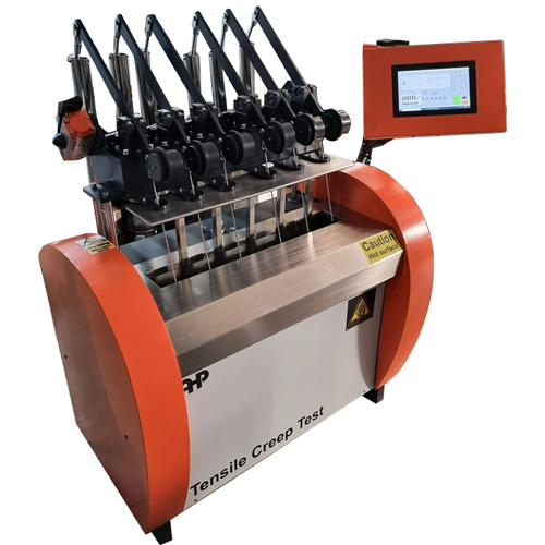
NCLS Tester According to ASTM F 2136 – ECO
- Computerized model
- Windows based software
- software is included
- PLC based
- Circulation system for temperature homogeneity
- Including 6 stations
- One station load cell channel to check forces of each station separately
- Pneumatic based sample elevator
- Lever mechanism force application
- Pneumatic actuator for force application
- Notch making manual press is included
- Press for sample hole clips
- SS304 internal bath
- Stop switch for each channel to record time
- Software according to ASTM F2136
- Computer is not included (Laptop and installation arm will be quoted separately)
- Easy assembly of samples on testing place
- Force application using dead weight mechanism
- Flange type heating elements
- Blanking die and manual press is included
- Notching device with micrometer
- Microscope for notch depth control is not included (Will be quoted separately in case of customer need)
- Compression-Molding Press (Will be quoted separately in case of customer need)
- Training video is included
