Differential scanning calorimetry (DSC) –
Part 6: Determination of oxidation induction time (isothermal OIT) and oxidation induction temperature (dynamic OIT) (ISO 11357-6:2008)
1 Scope
This part of ISO 11357 specifies methods for the determination of oxidation induction time (isothermal OIT) and oxidation induction temperature (dynamic OIT) of polymeric materials by means of differential scanning calorimetry (DSC). It is applicable to polyolefin resins that are in a fully stabilized or compounded form, either as raw materials or finished products. It may be applicable to other plastics.
4 Principle
4.1 General
The time for which, or the temperature up to which, an antioxidant stabilizer system present in a test specimen inhibits oxidation is measured while the specimen is held isothermally at a specified temperature or heated at a constant rate in an oxygen or air atmosphere. The oxidation induction time or temperature is an assessment of the level (or degree) of stabilization of the material tested. Higher test temperatures will result in shorter oxidation induction times; faster heating rates will result in higher oxidation induction temperatures. The oxidation induction time and temperature are also dependent on the surface area of the specimen available for oxidation. It should be noted that tests carried out in pure oxygen will result in a lower oxidation induction time or temperature than tests performed under normal atmospheric-air conditions.
NOTE The oxidation induction time or temperature can be indicative of the effective antioxidant level present in the
test specimen. Caution should be exercised in data interpretation, however, since oxidation reaction kinetics are a function of temperature and the inherent properties of the additives contained in the sample. For example, oxidation induction time or temperature results are often used to select optimum resin formulations. Volatile antioxidants or differences in activation energies of oxidation reactions may generate poor oxidation induction time or temperature results, even though the antioxidants may perform adequately at the intended temperature of use of the finished product.
4.2 Oxidation induction time (isothermal OIT)
The specimen and a reference material are heated at a constant rate in an inert gaseous environment (a flow of nitrogen). When the specified temperature has been reached, the atmosphere is changed to oxygen or air maintained at the same flow rate. The specimen is then held at constant temperature until the oxidative reaction is displayed on the thermal curve. The isothermal OIT is the time interval between the initiation of oxygen or air flow and the onset of the oxidative reaction. The onset of oxidation is indicated by an abrupt increase in the specimen’s evolved heat and may be observed by a differential scanning calorimeter (DSC). The isothermal OIT is determined in accordance with 9.6.1.
4.3 Oxidation induction temperature (dynamic OIT)
The specimen and a reference material are heated at a constant rate in an oxygen or air atmosphere until the oxidative reaction is displayed on the thermal curve. The dynamic OIT is the temperature of the onset of the oxidative reaction. The onset of oxidation is indicated by an abrupt increase in the specimen’s evolved heat and may be observed by a differential scanning calorimeter (DSC). The dynamic OIT is determined in accordance with 9.6.2.
5 Apparatus and materials
5.1 General
See also ISO 11357-1:—, Clause 5.
Subclauses 5.5 to 5.8 shall be followed as applicable (Subclauses 5.7 and 5.8 are required only for oxidation induction time measurements).
5.2 DSC instrument
The DSC instrument shall be able to achieve a maximum temperature of at least 500 °C. For oxidation induction time measurements, it shall be capable of maintaining an isothermal stability of ± 0,3 °C at the test temperature over the duration of the test, typically 60 min.
For high-precision measurements, an isothermal stability of ± 0,1 °C is recommended.
5.3 Crucibles
Specimens shall be placed in open or closed ventilated crucibles that allow unperturbed contact with the surrounding atmosphere. Preferably, crucibles should be made of aluminium. Crucibles made of different materials may be used by agreement between the interested parties.
NOTE The composition of the crucible material can influence the oxidation induction time or temperature test result significantly (that is, including any associated catalytic effects). The type of containment system used depends on the intended application of the material being tested. Polyolefins used in the wire and cable industry typically require copper or aluminium crucibles whereas, for polyolefins used in geomembrane and vapour-barrier film applications, only aluminium crucibles are used.
5.4 Flowmeter
For gas flow calibration, a flow rate measuring device such as a rotameter or soap-film flowmeter shall be used together with a flow-adjusting valve. Mass flow controlling devices shall be calibrated against a positive-displacement device.
5.5 Oxygen
The oxygen used shall be of 99,5 % ultra-high-purity grade (extra dry) or better.
WARNING — The use of pressurized gas requires safe and proper handling. Furthermore, oxygen is a strong oxidizer that accelerates combustion vigorously. Keep oil and grease away from equipment using or containing oxygen.
5.6 Air
The pressurized air used shall be dry and free of oil and grease.
5.7 Nitrogen
The nitrogen used shall be of 99,99 % ultra-high-purity grade (extra dry) or better.
5.8 Gas-selector switch and regulators
The DSC apparatus used for oxidation induction time measurements needs to be switched between nitrogen and oxygen or air. The distance between the gas-switching point and the instrument cell should preferably be kept as short as possible, with a dead time of less than 1 min, to minimize the switching volume. Accordingly, for a flow rate of 50 ml/min, the dead volume would have to be less than 50 ml.
NOTE Increased precision can be obtained if the dead time is known. One possible means of determining dead time is to carry out a test using a non-stabilized material which will oxidize immediately in the presence of oxygen. The induction time from this test will provide a correction for subsequent OIT determinations.
6 Test specimens
6.1 General
See ISO 11357-1:—, Clause 6.
Specimens shall have a constant thickness of (650 ± 100) µm and parallel surfaces, shall be flat and shall not show any burrs or scars.
NOTE Depending on the material and its process history, dimensions and service conditions, the methods of sample and specimen preparation may be crucial to the consistency of the results and their significance. In addition, the surface to volume ratio of the test specimen, poor specimen uniformity, residual stresses or lack of contact between specimen and crucible can affect test precision adversely.
If measurements of the OIT profile across the specimen thickness are required, specimens of significantly lower thickness than 650 µm may need to be used. This shall be noted in the test report.
6.2 Specimens from compression-moulded plates
Following ISO 293 or any other relevant polyolefin product standard such as ISO 1872-2 for PE, ISO 1873-2 for PP or ISO 8986-2 for PB-1, the test sample shall be compression-moulded into sheet of thickness complying with 6.1 to yield consistent specimen morphology and thickness. Alternatively, a specimen of suitable thickness can be cut from a thicker compression-moulded plate. If no heating time is specified in the relevant product standard, heating at the moulding temperature shall be limited to 5 min. Preferably, a borehole cutter should be used to punch out from the plate a disc of diameter just less than the inner diameter of the sample crucible. Specimen discs shall be small enough to lay flat in the crucible and shall not be stacked to increase mass.
NOTE Specimen mass will vary depending on disc diameter. For a typical diameter of 5,5 mm, specimen discs cut from sheet will have a mass of approximately 12 mg to 17 mg, depending on the density of the material.
6.3 Specimens from injection-moulded plates or melt flow extrudates
Specimens may also be obtained from injection-moulded samples of thickness complying with 6.1, e.g. prepared in accordance with ISO 294-3 or any other relevant polyolefin product standard such as ISO 1872-2 for PE, ISO 1873-2 for PP or ISO 8986-2 for PB-1. Preferably, a bore-hole cutter should be used to punch out a disc of diameter just less than the inner diameter of the sample crucible.
Specimens can also be cut from melt flow indexer extrudates. In this case, the specimen shall be cut perpendicular to the extrudate length. A visual inspection of the specimen shall be performed to ensure that it is free of voids. Preferably, a microtome should be used to cut specimens to a constant thickness of
(650 ± 100) µm.
6.4 Specimens from finished parts
Examples of such parts are pipes and fittings. Disc-shaped pieces shall be cut from the finished part in accordance with the referring standard so as to obtain specimens of thickness (650 ± 100) µm.
The following procedure is recommended to prepare specimens from thick-walled finished parts: obtain a cross-section of the wall by using a core drill directed radially through the wall, where the diameter of the core is just less than the inner diameter of the sample crucible. Take care not to overheat the specimen during the cutting operation. Cut discs of specified thickness from the core, preferably by using a microtome. If surface effects are of prime interest, cut discs from the inner and outer surfaces and test them with the original surface facing upward. If the characteristics of the base material are desired, cut a middle-section disc by removing the outer and inner surfaces.
8 Calibration
8.1 Oxidation induction time (isothermal OIT)
A modified two-point calibration procedure shall be used. Indium and tin can be used as calibration materials for polyolefins since their respective melting points encompass the specified analysis temperature range (180 °C to 230 °C). If other plastics are investigated, other calibration materials may need to be used. The instrument shall be calibrated in accordance with ISO 11357-1:—, Clause 8. Calibration shall be performed under nitrogen using closed crucibles.
The following melting profiles shall be used if the calibration procedure does not provide heating-rate correction:
Indium: ambient to 145 °C at 10 °C/min, 145 °C to 165 °C at 1 °C/min
Tin: ambient to 220 °C at 10 °C/min, 220 °C to 240 °C at 1 °C/min
9 Procedure
9.1 Setting up the instrument
See ISO 11357-1:—, Subclause 9.1.
9.2 Loading the test specimen into the crucible
See ISO 11357-1:—, Subclause 9.2.
If the specimen is cut from the inner or outer surface of a pipe or fitting, it shall be placed in the crucible with the surface of interest facing upward. The test specimen shall be weighed to the nearest ± 0,5 mg, as heat flow is not the main point of interest in this case. The specimen disc is placed into the appropriate crucible type. If a cover is necessary, it shall be pierced to permit flow of oxygen or air to the specimen. Crucibles shall not be sealed unless they are ventilated.
9.3 Insertion of crucibles
See ISO 11357-1:—, Subclause 9.3.
9.4 Nitrogen, air and oxygen flow
The nitrogen or air purge gas flow rates used for measurements and calibration shall be the same. Any change in flow rate requires recalibration. A typical purge gas flow rate is (50 ± 5) ml/min.
The flow rate of oxidizing gas shall be the same as that used for nitrogen.
9.5 Sensitivity adjustment
The instrument sensitivity shall be adjusted so that the difference in vertical height on the stepped change curve becomes 50 % or more of the full scale of the recording device. Computer-controlled instruments do not need this adjustment.
9.6 Performance of measurement
9.6.1 Oxidation induction time (isothermal OIT)
Load specimen and reference crucibles at ambient temperature. Pre-purge the instrument with nitrogen for 5 min prior to beginning the heating cycle.
Programmed heating of the specimen under nitrogen flow shall be started from ambient temperature and continued to the test temperature at a rate of 20 °C/min. Preferably, isothermal test temperatures shall be chosen to full 10 °C values and changed only in steps of full 10 °C. Other test temperatures may be used as specified by a reference standard or by agreement between the interested parties. Particularly, specimens yielding oxidation induction times of less than 10 min should be retested at a lower temperature. Specimens yielding oxidation induction times of greater than 60 min should be retested at a higher temperature.
When the set temperature has been reached, programmed heating shall be discontinued and the specimen shall be equilibrated for 3 min at the set temperature.
The recorder shall be turned on.
Once the equilibrium time has expired, the gas shall be changed to oxygen or air at a flow rate identical to the rate used for nitrogen. This changeover point to oxygen or air flow shall be marked as the zero time of the test.
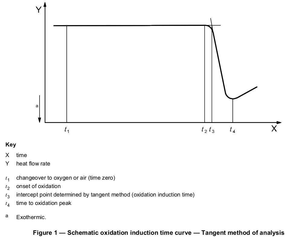
The isothermal operation shall be continued until at least 2 min have elapsed after the steepest point of the exotherm has been displayed (see Figure 1). Alternatively, the test may be terminated if time requirements stated in the product specification or agreed between the interested parties have been met.
Upon completion of the test, the gas selector should be switched back to nitrogen and the instrument cooled down to ambient temperature. If additional testing is being conducted, cooling the instrument cell below 60 °C should be sufficient.
The number of tests to be carried out on each sample shall be established by agreement between the interested parties. Preferably, specimens should be tested in duplicate, and the arithmetic mean as well as the lower and upper values reported.
NOTE Oxidative induction time is a complex function of temperature and the additives in the polymer. Therefore, extrapolation or comparison of data obtained at different temperatures is not valid unless justified by experimental results.
9.6.2 Oxidation induction temperature (dynamic OIT)
The instrument shall be pre-purged with the purge gas to be used for measuring, i.e. oxygen or air, for 5 min with the specimen and reference crucibles loaded at ambient temperature prior to beginning the heating cycle.
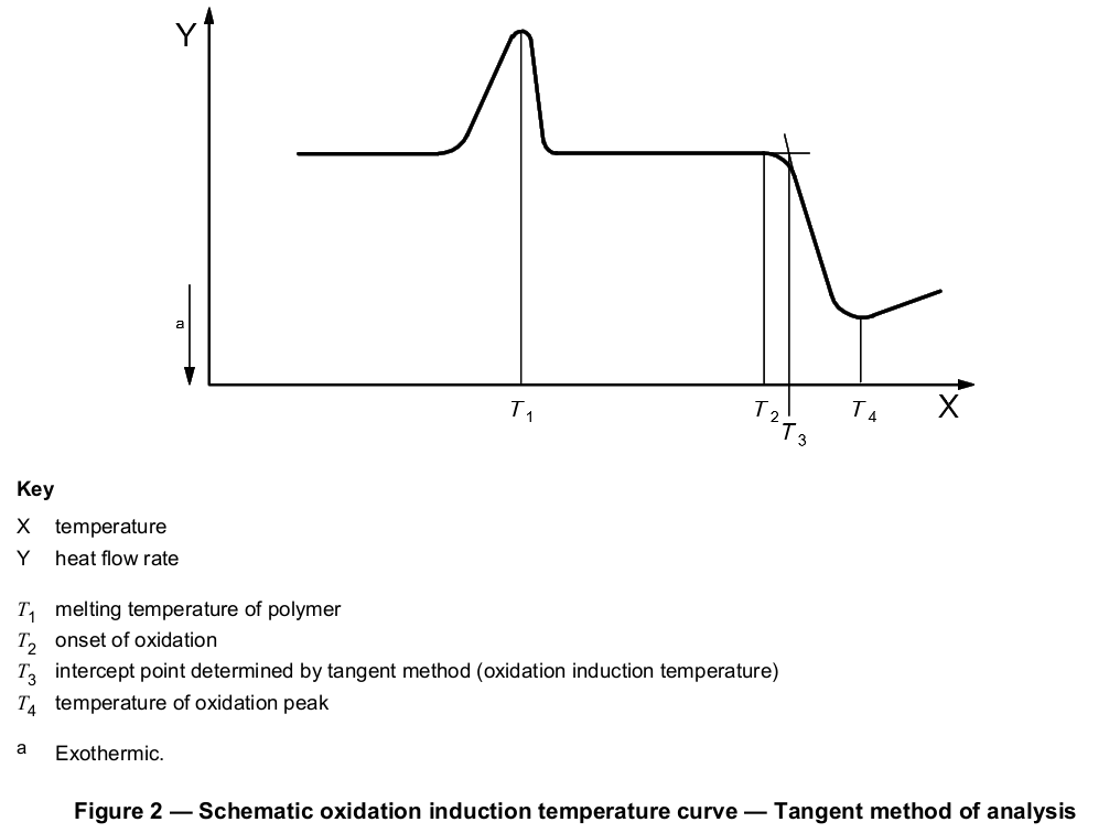
Programmed heating of the specimen under oxygen or air flow shall be started at ambient temperature and continued to a temperature at least 30 °C above the steepest point on the exotherm (see Figure 2). Preferred heating rates are 10 °C/min and 20 °C/min. Alternatively, the test may be terminated if temperature requirements stated in the product specification or agreed between the interested parties have been met.
Upon completion of the test, the instrument should be cooled down to ambient temperature. If additional testing is being conducted, cooling the instrument cell below 60 °C should be sufficient.
The number of tests to be carried out on each sample shall be established by agreement between the interested parties. Preferably, specimens should be tested in duplicate, and the arithmetic mean as well as the lower and upper values reported.
9.7 Cleaning
Cleaning the measuring cell of the DSC instrument of contamination by heating to at least 500 °C for 5 min in air or oxygen shall be done at frequencies established in the relevant certification procedure or in the case of deviating results. As a measure of precaution, cleaning frequencies should comply with good laboratory practice.
10 Expression of results
The data shall be plotted with the heat flow rate on the Y-axis and time or temperature, as applicable, on the X-axis. In the case of manual evaluation, the X-axis should be expanded as much as possible to facilitate analysis.
The recorded baseline shall be extended well beyond the onset of the oxidative reaction exotherm. The steepest linear slope of this exotherm shall be extrapolated to intercept the extended baseline (see Figure 1 or 2). The intercept point representing the oxidation induction time or temperature shall be measured to a resolution of three significant figures.
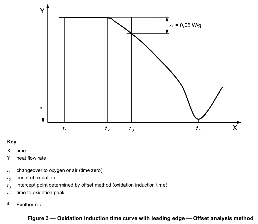
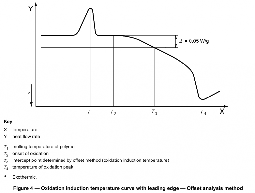
The tangent method described above is the preferred means of determining the intercept point, but the selection of the appropriate tangent to the exotherm may be difficult if the exothermic peak has a leading edge. Exothermic peaks with leading edges may occur if the oxidation reaction is slow. If the selection of the appropriate slope to be used for the tangent method is not obvious, an offset method may be used. A second baseline shall be drawn parallel to the first baseline at a threshold distance of 0,05 W/g (see Figure 3 or 4) from the first baseline (see next paragraph). The intersection of this second line with the exotherm signal is defined as the onset of oxidation.
Thermograms having leading edges can also be due to poor specimen preparation, i.e. specimens being of varying thickness, not being flat or having burrs or scars. Thus, before applying the threshold method described for evaluation of results, it is recommended that the scan be repeated, making sure that all specimen requirements described in Clause 6 are properly met, to confirm the leading edge shape of the thermogram.
Other procedures or other values for the threshold distance from the baseline may be used by agreement between the interested parties.
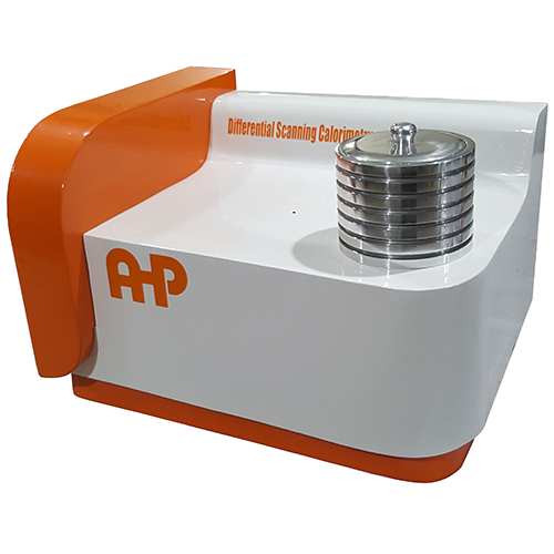
DSC for determining the oxidation induction time for polymer pipe and protective pipe systems as well as moulded elements made of polyolefin. Suitable for OIT test, Melting point, Tg, …. determination
- According to ASTM D3895 ISO11357 EN728 ASTM D3418
- Up to 300C (Other temperature ranges on customer request 500C, 600C, …)
- Including standard Tin, Ind pellets for calibration checkout
- 400 pcs of aluminium pans
- Software CD (windows based software including Report out to WORD)
- N2 and O2 rotameter mass flow controller
- Hoses and connectors
- Software also has data export to advantage Software for analysis
- DSC measuring cell according to the heat flux principle
- Temperature sensors for control & sample temperature
- Connection for Purge gas flow to the sample for 2 gas types
- Temperature accuracy 0.1 C
- Sensitivity: 3.6 to 4.0 μV/mW
- Sensor Time constant: 2.5 s
- Calorimeter accuracy of ± 2%
- Calorimetric precision of ± 0.5% or better
- Two connections for purge gas-Inlet to the sample & 1 connection for cooling air
- Software is included
