

1. Introduction
Plastics and polymeric materials exhibit viscoelastic behavior, meaning that their deformation depends not only on the magnitude of the applied stress but also on time, temperature, loading rate, and environmental conditions.
For this reason, the results of a conventional short-term tensile, compression, or flexural test cannot by themselves predict how a plastic component will behave when subjected to a constant load for hundreds or thousands of hours.
ASTM D2990 provides standardized procedures for evaluating:
- Tensile creep
- Compressive creep
- Flexural creep
- Tensile creep-rupture
- Compressive creep-rupture
The fundamental principle of the test is to apply a specified constant load to a conditioned specimen under controlled environmental conditions and measure the resulting deformation as a function of time.
Creep testing is primarily used to determine the long-term dimensional stability and creep modulus of plastics, while creep-rupture testing is used to determine the time required for failure or rupture under a sustained load.
2. What Is Creep?
Creep is the progressive deformation of a material with time while it is subjected to a sustained load or stress.
When a constant load is applied to a polymer specimen, an initial deformation normally occurs immediately. Additional deformation then develops progressively with time.
Therefore, the total strain measured during an ASTM D2990 creep test includes both the initial strain associated with application of the load and the subsequent time-dependent deformation.
A typical creep curve can contain three characteristic regions:
Primary Creep – Stage I
Immediately after loading, deformation increases relatively rapidly, but the creep rate progressively decreases with time.
Secondary Creep – Stage II
The creep rate approaches a relatively steady value.
This region can represent a substantial portion of the useful long-term behavior of a material.
Tertiary Creep – Stage III
The creep rate increases rapidly and may eventually lead to rupture or failure.
Not every polymer necessarily exhibits all three regions clearly. The shape of the creep curve depends strongly on material type, stress, temperature and environment.
3. Difference Between Creep and Creep-Rupture Testing
Although both tests involve sustained loading, their objectives are different.
Creep Test
In a creep test, deformation is measured as a function of time under a specified constant load.
Typical outputs include:
- Creep strain versus time
- Creep modulus versus time
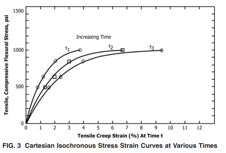
- Isochronous stress-strain curves
- Stress required to produce a specified strain after a specified period
Creep-Rupture Test
In creep-rupture testing, the specimen remains under sustained load until rupture or another defined failure condition occurs.
The principal parameters are:
- Applied stress
- Time-to-rupture
- Time-to-failure
- Temperature
- Environmental conditions
For long-term structural applications, these results can be used to establish the relationship between stress and allowable service time.
4. Loading Configurations Covered by ASTM D2990
ASTM D2990 allows creep behavior to be investigated under different loading configurations.
4.1 Tensile Creep
A constant tensile load is applied along the longitudinal axis of the specimen. The increase in gauge length is measured as a function of time.
4.2 Compressive Creep
A constant compressive load is applied to the specimen and the decrease in its length is measured. Special attention must be paid to specimen alignment and buckling.
4.3 Flexural Creep
The specimen is supported as a beam and subjected to a constant bending load.
ASTM D2990 principally describes three-point loading, following the principles of ASTM D790.
Four-point loading using the equipment and principles of ASTM D6272 is also permitted.
For creep-rupture measurements, tensile loading is generally preferred because some ductile plastics may deform extensively without rupturing in compression or flexure.
5. Required Creep Test Equipment
A creep testing system should be capable of applying and maintaining a stable load for extended periods while accurately measuring relatively small changes in specimen deformation.
The major requirements are described below.
6. Loading System
The loading mechanism must maintain the load applied to the specimen within:
±1% of the desired load
The system must also permit rapid, smooth and reproducible application of the load.
Typical loading arrangements may include:
- Dead-weight loading
- Lever-arm loading systems
- Mechanically amplified dead weights
- Other systems capable of maintaining a sufficiently constant load
Where a lever system is used, its geometry must be designed so that movement of the lever during specimen deformation does not significantly change the applied load.
For multi-station creep-rupture equipment, rupture of one specimen must not introduce shock loading into neighboring specimens.
7. Tensile Creep Grips
The tensile grips must minimize eccentric loading.
Misalignment is especially important in long-duration creep testing because even relatively small bending stresses can influence the measured deformation.
Swivel or universal joints should therefore be provided beyond both ends of the specimen.
The gripping arrangement should preferably allow final centering of the specimen before application of the load.
A gripping system that allows the specimen to move or slip inside the grips while the test load is being applied is not suitable.
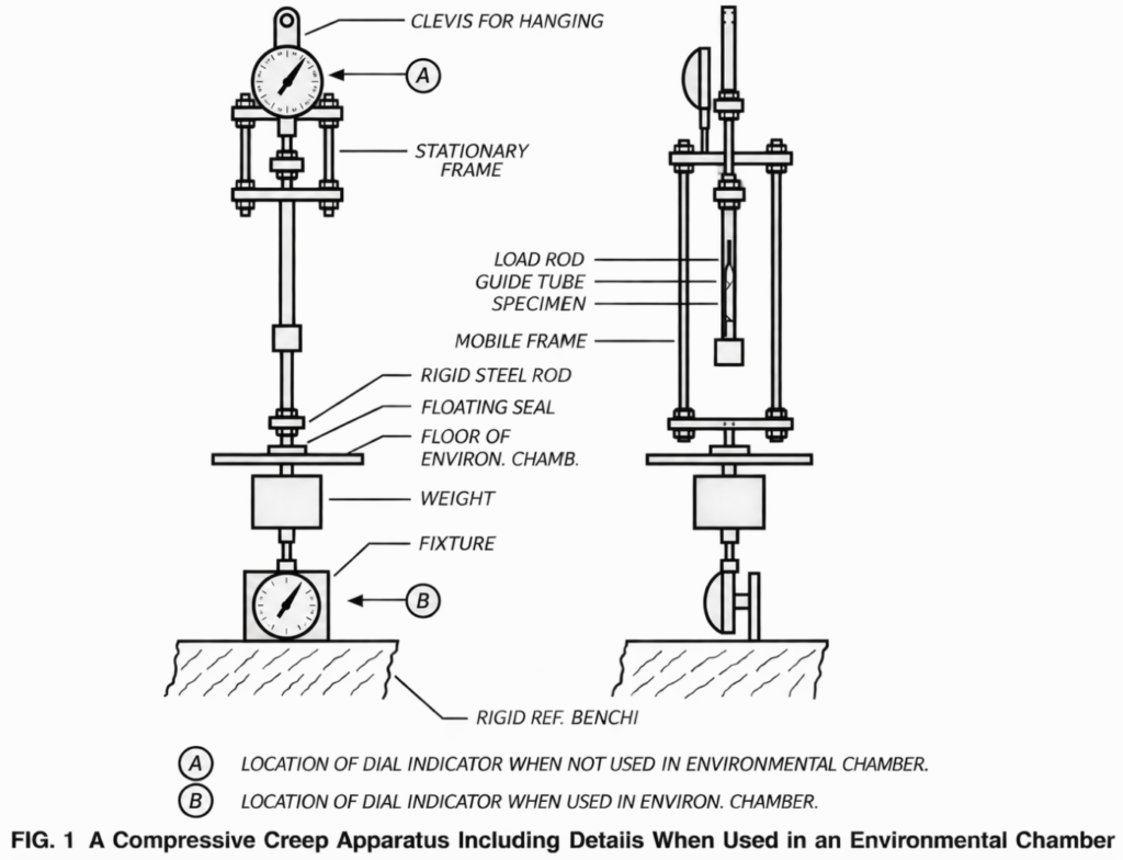
8. Compressive Creep Fixture
For unconfined compression testing, parallel anvils are used.
Preferably, one anvil should be self-aligning so that:
- the specimen is properly centered;
- the load is uniformly distributed over the specimen face;
- the resultant force passes through the specimen center.
For slender specimens, ASTM D2990 specifies the use of a guide tube and suitable fixtures to prevent buckling.
This is particularly important because buckling would convert a nominal compression test into a combined compression/bending condition and invalidate the creep measurement.
9. Flexural Creep Fixture
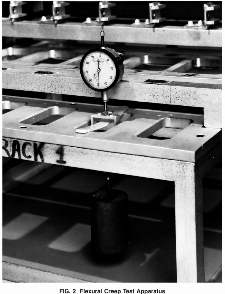
For flexural creep testing, the specimen is supported at both ends on a rigid test rack.
The support span should be: 16 (+4 /−2) × specimen thickness
The support radius should be approximately: 3.2 mm
A stirrup is positioned at the specimen mid-span and the required dead weight is suspended from it.
The radius of the loading contact surface should also be approximately: 3.2 mm
This radius helps reduce excessive local indentation and stress concentration.
The complete loading arrangement must remain properly aligned so that the load is applied uniformly at the required location.
10. Deformation Measurement System
Depending on the loading mode, the system must measure:
- Extension in tensile creep
- Compression in compressive creep
- Mid-span deflection in flexural creep
The deformation measuring system must not significantly affect specimen behavior.
In particular, it must not introduce:
- mechanical damage;
- additional deformation;
- notches;
- heating;
- chemical interaction.
Whenever possible, tensile extension should be measured directly from the specimen rather than indirectly from grip separation.
If grip displacement is used, suitable correction factors must be established so that the actual strain within the specimen gauge length can be determined.
For flexural creep, mid-span deflection may be measured with a suitable dial indicator or other appropriate displacement measuring device.
The required accuracy of the deformation measuring device is: ±1% of the deformation being measured
The measuring system should be calibrated against a precision micrometer or another suitable reference under conditions as close as practical to those of the actual test.
Long-duration stability is particularly important because sensor drift caused by temperature, humidity or time may be incorrectly interpreted as material creep.
11. Temperature Control
Temperature is one of the most important variables in polymer creep testing.
The temperature near the specimen gauge section must be maintained within: ±2°C
The temperature measuring device should represent the actual temperature in the specimen gauge region rather than merely the general chamber temperature.
Temperature should be measured frequently or continuously recorded throughout the test.
Even relatively small temperature fluctuations can cause thermal expansion or contraction that appears as changes in creep deformation, particularly when testing near material transition temperatures.
12. Humidity and Environmental Control
When testing in air, relative humidity should normally be maintained within: ±5% RH
unless another condition is specified or the material has been demonstrated to be insensitive to humidity.
The environmental control and measurement system must be sufficiently stable for long-duration testing.
When liquids, chemicals or other environments are used, their composition must remain sufficiently constant throughout the test.
13. Vibration Isolation
Creep measurements are sensitive to vibration and mechanical shock.
The creep test frame should therefore be installed on a stable structure and isolated as far as practical from:
- vibration;
- impact;
- movement of nearby machinery;
- shock generated by rupture of neighboring specimens.
For creep-rupture testing, a failed specimen and its falling weight must not disturb other specimens.
Suitable nets, cushions or other protective arrangements can be used beneath the loading system.
14. Preparation of Test Specimens
Specimen preparation is one of the most important parts of ASTM D2990 testing.
Before selecting specimen geometry, the applicable material specification must be checked.
Where the material specification defines specimen preparation, dimensions, conditioning or test conditions, those requirements take precedence over the general ASTM D2990 conditions when applicable.
15. Tensile Creep Specimens
Specimens for tensile creep are prepared using: ASTM D638 Type I or Type II specimens
Specimens specified in ASTM D1822 may also be used for creep-rupture testing.
If necessary, the specimen tabs may be trimmed to fit the grips, provided that proper gripping and axial loading can still be achieved.
Care should be taken not to introduce:
- scratches;
- sharp machining marks;
- excessive heating;
- localized thinning;
- residual stresses
into the gauge section during specimen preparation.
16. Unconfined Compressive Creep Specimens
Specimens for unconfined compressive creep are prepared generally according to ASTM D695, except that their length is increased so that the required slenderness ratio is achieved.
The required slenderness ratio is: 11 to 15
The specimen should be a:
- right cylinder, or
- right prism.
Preferred cross-sections are: 12.7 × 12.7 mm
or 12.7 mm diameter
The loading surfaces must be flat and parallel.
This is essential because nonparallel end surfaces produce uneven compressive loading and may introduce bending.
17. Slender Compression Specimen Used with a Guide Tube
For compression creep measurements using the guide arrangement described in ASTM D2990, the specimen is a slender square bar.
Specified dimensions are approximately:
Square side: 4.850 ± 0.025 mm
Diagonal: 6.860 ± 0.025 mm
Length: 51 mm
The specimen ends must be machined perpendicular to its longitudinal sides.
The guide arrangement prevents lateral instability or buckling during sustained compressive loading.
18. Flexural Creep Specimens
Flexural creep specimens are rectangular bars conforming to the relevant specimen requirements of ASTM D790.
Preferred dimensions given in ASTM D2990 are:
Smaller specimen
63.5 × 12.7 × 3.18 mm
Larger specimen
127 × 12.7 × 6.4 mm
Exact specimen and span dimensions do not need to equal the preferred nominal dimensions provided that the actual measured dimensions are used when calculating the required load and stress.
19. Methods of Producing Specimens
Suitable specimen manufacturing methods include:
- Injection molding
- Compression molding
- Machining from sheet
- Machining from fabricated products or other forms
An extremely important requirement applies when creep testing is being performed to obtain engineering design data:
The specimen fabrication method should represent the fabrication process of the actual application.
This is important because processing history can significantly influence:
- molecular orientation;
- crystallinity;
- residual stress;
- fiber orientation in reinforced plastics;
- weld lines;
- density distribution;
- long-term creep response.
Therefore, a machined specimen and an injection-molded specimen manufactured from nominally the same polymer may not necessarily produce identical long-term creep behavior.
20. Specimen Orientation
When specimens are machined from sheet, all specimens belonging to a test series should be cut in the same direction. If anisotropy is suspected, specimens should be prepared in both principal sheet directions.
For example:
- Machine Direction – MD
- Transverse Direction – TD
Results from the two directions should then be evaluated separately.
This is particularly important for:
- extruded sheet;
- oriented thermoplastics;
- fiber-reinforced plastics;
- materials containing fillers with preferential orientation.
21. Dimensional Measurement of Specimens
Before testing, specimen dimensions must be measured at room temperature.
Measurements should be made at five or more locations along the gauge length or flexural span.
Width should be measured to the nearest: 0.025 mm
Thickness should be measured to the nearest: 0.005 mm
The initial dimensions are subsequently used for calculation of stress and strain.
For tensile and compression tests, stress is calculated from the original cross-sectional area rather than the progressively changing area during creep.
22. Control Specimens for Environmentally Induced Dimensional Change
Certain plastics can change dimensions because of the test environment even when no mechanical load is applied. Examples include thermal shrinkage, post-curing or other environmentally induced dimensional changes. When this effect is significant, unloaded control specimens must be placed under the same environmental conditions as the loaded specimens.
At least: 3 unloaded control specimens per test temperature should be used.
The dimensional changes measured from these controls can subsequently be used to distinguish deformation caused by the environment from deformation caused by mechanical creep.
23. Number of Specimens
For creep testing at a single temperature:
If four or more stress levels are used: minimum 2 specimens per stress level
If fewer than four stress levels are used: minimum 3 specimens per stress level
For creep-rupture testing: minimum 2 specimens per stress level at each temperature
should be tested.
Creep-rupture results may show substantial scatter, so using more specimens can significantly improve confidence in the resulting stress-rupture relationship.
24. Conditioning Before Testing
Proper conditioning is essential because moisture and temperature history can significantly affect polymer creep.
Where conditioning is required, specimens are conditioned according to ASTM D618 Procedure A at:
23 ± 2°C and 50 ± 10% relative humidity
for at least: 40 hours before testing.
25. Preconditioning in the Actual Test Environment
In addition to standard conditioning, ASTM D2990 requires the specimen to be preconditioned in the actual test environment for at least: 48 hours
before testing.
For materials whose creep behavior is affected by moisture, specimens should be brought to an appropriate moisture equilibrium corresponding to the intended test conditions.
This requirement is particularly important for hygroscopic polymers.
26. Selection of Test Temperature
Test temperature should be selected according to the purpose of the test.
Material Characterization
Two or more temperatures should be selected to cover the useful service range of the material.
Temperatures should be selected so that important changes in creep response or material transitions can be detected.
Engineering Design Data
When the objective is engineering design, the temperature and environment should reproduce the intended service conditions as closely as practical.
Standard Material Comparison
For simple comparisons, ASTM D2990 identifies the following useful test temperatures:
- 23°C
- 50°C
- 70°C
- 90°C
- 120°C
- 155°C
The appropriate temperatures depend on the polymer and intended application.
27. Selection of Stress Levels for Creep-Rupture Testing
For creep-rupture testing at each temperature, ASTM D2990 specifies a minimum of seven stress levels selected to produce rupture at approximately:
- 1 hour
- 10 hours
- 30 hours
- 100 hours
- 300 hours
- 1000 hours
- 3000 hours
The resulting data are used to construct a stress-at-rupture versus time-to-rupture curve, often described as a creep-rupture envelope.
For applications involving sustained loading for six months or longer, tests longer than 3000 hours may be required.
This becomes especially important:
- at elevated temperatures;
- where thermal aging occurs;
- in chemically aggressive environments.
28. Definition of Failure in Creep-Rupture Testing
For materials that rupture catastrophically with little preceding flow or yielding: time-to-rupture is recorded.
For materials that undergo substantial yielding, drawing or flow before physical rupture, the onset of tertiary creep is treated as the time-to-failure.
For these materials, continuous or sufficiently frequent strain recording is particularly important.
29. Selection of Stress Levels for Creep Testing
If the material behaves approximately as a linear viscoelastic material, at least: 3 stress levels per test temperature should be used.
If creep behavior is significantly stress-dependent: at least 5 stress levels per temperature should be selected, and preferably more.
The selected stress levels should extend approximately uniformly toward the relevant long-term creep-rupture stress.
A stress level that causes failure in less than: 1000 hours
should not be used for a conventional creep test intended under this criterion.
30. Determination of Stress Producing 1% Strain at 1000 Hours
For simple comparison of materials, ASTM D2990 provides a useful long-term parameter:
Stress required to produce 1% strain after 1000 hours
Several load levels are selected so that the resulting 1000-hour strains lie both above and below approximately 1%.
A 1000-hour isochronous stress-strain curve is then constructed.
The stress corresponding to exactly 1% strain is determined by interpolation.
At least three creep tests at different stress levels are normally necessary to construct such a curve, with additional levels preferred for improved definition.
31. Step-by-Step ASTM D2990 Test Procedure
Step 1 – Prepare the Specimens
Produce the specimens using the appropriate molding or machining method.
Verify:
- geometry;
- orientation;
- surface condition;
- absence of visible damage;
- perpendicularity where applicable;
- flatness and parallelism of compression surfaces.
Step 2 – Condition the Specimens
Condition the specimens under the required standard conditions and then precondition them in the actual test environment.
Step 3 – Measure the Specimens
Measure width and thickness at five or more positions. Record all measurements. Determine the appropriate initial cross-sectional area.
Step 4 – Prepare Control Specimens Where Required
If environmental dimensional changes are expected, prepare at least three unloaded control specimens for each test temperature.
Place them under the same environmental conditions as the loaded specimens.
Step 5 – Install the Specimen
Mount the conditioned and measured specimen in the appropriate:
- tensile grips;
- compression fixture; or
- flexural creep rack.
Alignment must be carefully checked before loading.
Step 6 – Install the Deformation Measurement System
Attach the displacement or strain measurement device to the specimen. For optical systems, position and zero the system before testing.
If installation of the measuring device after placing the specimen in the environmental chamber would disturb the controlled environment, the measuring device should be installed beforehand.
Step 7 – Establish the Reference Reading
Before application of the main test load, establish the initial/reference deformation reading. This becomes the reference from which subsequent creep deformation is calculated.
Step 8 – Apply the Test Load
Apply the full test load rapidly and smoothly.
Preferred loading time: 1 to 5 seconds
Maximum permitted loading time: 5 seconds
Timing of the creep test starts at the onset of loading.
Accurate timing of this step is important because the initial portion of polymer creep can occur rapidly.
32. Testing in a Chemical or Liquid Environment
If an environmental agent is part of the test, it should be applied over the entire specimen gauge length immediately after loading. If the environmental agent is volatile, evaporation should be minimized without altering the mechanical loading.
The agent should be replenished when necessary.
For liquid agents, a suitable absorbent or containment arrangement may be positioned around the gauge length or flexural span and saturated with the liquid.
The chemical composition and concentration must remain controlled throughout the test.
33. Creep Deformation Measurement Schedule
ASTM D2990 provides the following approximate schedule for recording deformation:
During the first hour
- 1 minute
- 6 minutes
- 12 minutes
- 30 minutes
- 1 hour
Longer-term readings
- 2 hours
- 5 hours
- 20 hours
- 50 hours
- 100 hours
- 200 hours
- 500 hours
- 700 hours
- 1000 hours
For tests longer than 1000 hours:
deformation should be measured at least monthly.
If the creep strain-time curve shows or is expected to show discontinuities or rapid transitions, measurements must be made more frequently.
34. Environmental Measurements During the Test
Temperature, relative humidity and any other relevant environmental parameters should be recorded according to the same general schedule as the deformation measurements.
Where control specimens are used, their dimensional changes should also be measured on the same schedule.
35. End of the Creep Test
If the specified test duration is reached without rupture, remove the load: rapidly and smoothly
to avoid introducing unnecessary dynamic effects.
Recovery measurements may optionally be continued after unloading.
Using the same general measurement schedule can provide useful information on the recoverable and permanent components of deformation.
36. Tensile and Compressive Stress Calculation
For tensile and compressive creep:
σ = P / A₀
where:
- σ = applied stress
- P = applied load
- A₀ = original average cross-sectional area of the specimen
The original area is used for calculating nominal creep stress.
37. Tensile and Compressive Creep Strain
Strain is determined from the change in gauge length:
ε = ΔL / L₀
where:
- ε = strain
- ΔL = extension or compression
- L₀ = initial conditioned gauge length
Percent strain is:
ε (%) = (ΔL / L₀) × 100
38. Three-Point Flexural Stress
For three-point flexural creep:
S = 3PL / (2bd²)
where:
- S = maximum outer-fiber stress
- P = applied load
- L = support span
- b = specimen width
- d = specimen thickness
39. Four-Point Flexural Stress
For four-point flexure with a load span equal to one-third of the support span:
S = PL / bd²
For four-point flexure with a load span equal to one-half of the support span:
S = 3PL / 4bd²
The selected equation must correspond to the actual loading geometry.
40. Flexural Creep Strain
For three-point bending, the maximum outer-fiber strain at mid-span is calculated as:
ε = 6Dd / L²
where:
- D = maximum mid-span deflection
- d = specimen thickness
- L = support span
Multiply by 100 to express the result as percent strain.
For four-point bending with a load span equal to one-third of the support span:
ε = 4.70Dd / L²
For a load span equal to one-half of the support span:
ε = 4.36Dd / L²
41. Creep Modulus
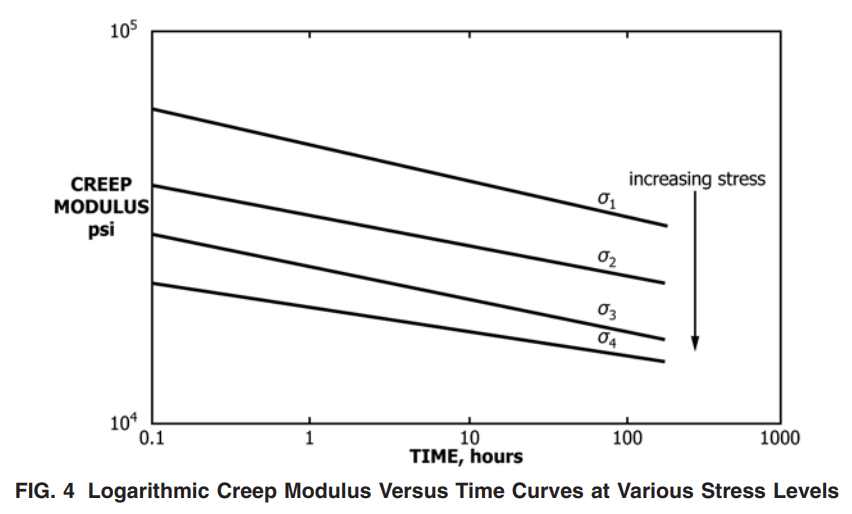
Creep modulus is calculated from:
Ecreep(t) = σ₀ / ε(t)
where:
- Ecreep(t) = creep modulus at time t
- σ₀ = initial applied stress
- ε(t) = creep strain at time t
Because strain normally increases with time under constant load, creep modulus generally decreases with time.
A plot of:
Creep Modulus vs. Time
is particularly useful for comparing the long-term stiffness of different plastics.
42. Correction for Environmental Dimensional Changes
When the unloaded control specimens show significant dimensional changes, deformation of the loaded specimens may need to be corrected.
The average dimensional change of the three unloaded control specimens at the same temperature and time is used.
The corrected deformation is then used to calculate corrected strain.
Depending on the intended use of the data, ASTM D2990 also permits reporting uncorrected strain, but the report must clearly identify whether the results are:
Corrected
or
Uncorrected
when environmental dimensional changes are significant.
43. Analysis of Creep-Rupture Data
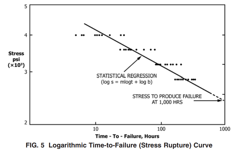
At each test temperature, a statistical regression of:
log stress versus log time-to-rupture or time-to-failure
is performed.
The regression can then be used to determine, for example, the stress corresponding to rupture or failure at:
1000 hours
The resulting stress-rupture curve is an important tool for evaluating long-term load-bearing capability.
44. Isochronous Stress-Strain Curves
An isochronous stress-strain curve represents stress versus creep strain at a fixed time.
For example, a 1000-hour isochronous curve is produced by taking the strain measured at 1000 hours from several creep tests performed at different stresses and plotting:
Stress vs. 1000-hour Creep Strain
At least three different stress levels are required, although more are preferred.
Isochronous curves can also be constructed at other times when required for specialized design analysis.
45. Recommended Creep Test Graphs
A comprehensive ASTM D2990 evaluation can include:
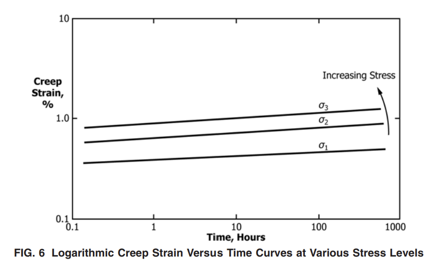
Creep Strain vs. Time
Shows the progressive deformation under sustained load.
Creep Modulus vs. Time
Shows the reduction in effective stiffness with time.
Stress vs. Time-to-Rupture
Used for creep-rupture evaluation and long-term strength assessment.
Isochronous Stress-Strain Curves
Shows the relationship between stress and strain at selected constant times.
For long-duration tests, logarithmic time scales are particularly useful because creep tests may extend over several orders of magnitude in time.
46. Required Information in the Test Report
A complete ASTM D2990 report should identify the tested material in sufficient detail.
The report should include, where applicable:
- Material description
- Composition
- Manufacturer
- Trade name
- Material identification or code number
- Manufacturing date
- Specimen preparation method
- Molding method
- Annealing or other thermal treatment
- Test dates
- Specimen dimensions
- ASTM D2990 designation and revision
- Test configuration
- Tensile, compression or flexural loading mode
- Conditioning procedure
- Preconditioning conditions
- Test temperature
- Relative humidity
- Environmental medium
- Environmental composition and concentration
- Applied loads
- Applied stress levels
- Loading arrangement
- Relevant deformation measurements
- Test duration
- Time-to-failure or time-to-rupture where applicable
- Corrected or uncorrected creep data where environmental dimensional changes are significant
47. Important Practical Considerations for Reliable Creep Testing
Because ASTM D2990 tests may continue for hundreds or thousands of hours, equipment characteristics that may be relatively unimportant in short-duration mechanical testing become critical.
Particular attention should therefore be given to:
Load Stability
The load must remain stable throughout the test.
Mechanical Alignment
Misalignment produces unintended bending stresses.
Sensor Stability
Long-term zero drift can be incorrectly interpreted as creep.
Temperature Stability
Small temperature variations can produce dimensional changes.
Specimen Slippage
Movement inside tensile grips invalidates extension measurements.
Vibration
Mechanical disturbances can influence sensitive displacement measurements.
Data Acquisition
Automated acquisition is advantageous for capturing the early rapid deformation and maintaining a complete long-duration test record.
Power Interruption
For long tests, the laboratory should consider appropriate protection against power interruptions, particularly where temperature control and automated data logging are required.
48. Why ASTM D2990 Is Important for Plastic Product Design
A plastic component may pass a conventional short-term tensile or flexural test and still deform excessively after months or years under a much lower constant load.
ASTM D2990 addresses this problem by characterizing material behavior as a function of:
Stress + Time + Temperature + Environment
The resulting data can therefore support:
- comparison of polymer grades;
- material selection;
- structural design;
- prediction of long-term dimensional stability;
- assessment of long-term load-bearing capability;
- evaluation of temperature effects;
- evaluation of environmental effects;
- determination of creep modulus;
- determination of stress producing a specified long-term strain;
- creep-rupture analysis.
49. Summary of Important ASTM D2990 Test Parameters
| Parameter | ASTM D2990 Requirement / Guidance |
|---|---|
| Test modes | Tensile, compression and flexural creep |
| Creep-rupture | Tensile and compression; tensile preferred in many cases |
| Load control | Within ±1% of desired load |
| Load application | Preferably 1–5 s; maximum 5 s |
| Temperature stability | ±2°C |
| Air humidity control | ±5% RH unless otherwise specified |
| Deformation measurement accuracy | ±1% of measured deformation |
| Tensile specimen | ASTM D638 Type I or Type II |
| Preferred compression cross-section | 12.7 × 12.7 mm or Ø12.7 mm |
| Compression slenderness ratio | 11–15 |
| Guide-tube compression specimen | 4.850 ± 0.025 mm square × 51 mm |
| Preferred flexural specimen | 63.5 × 12.7 × 3.18 mm |
| Alternative flexural specimen | 127 × 12.7 × 6.4 mm |
| Flexural support span | 16 (+4/−2) × specimen thickness |
| Support/loading radius | 3.2 mm |
| Width measurement resolution | 0.025 mm |
| Thickness measurement resolution | 0.005 mm |
| Dimensional measurement positions | At least 5 |
| Standard conditioning | 23 ± 2°C / 50 ± 10% RH |
| Minimum standard conditioning time | 40 h |
| Preconditioning in test environment | At least 48 h |
| Unloaded environmental controls | Minimum 3 per temperature where required |
| Creep-rupture stress levels | Minimum 7 |
| Approximate rupture targets | 1, 10, 30, 100, 300, 1000, 3000 h |
| Typical creep readings | 1, 6, 12, 30 min; 1, 2, 5, 20, 50, 100, 200, 500, 700, 1000 h |
| Tests beyond 1000 h | Deformation measurement at least monthly |
50. Conclusion
ASTM D2990 provides a comprehensive framework for determining the long-term creep and creep-rupture behavior of plastics under tensile, compressive and flexural loading.
Reliable results depend not only on applying a constant load but also on precise control of specimen geometry, preparation method, orientation, conditioning, temperature, humidity, loading alignment, deformation measurement and data acquisition.
For engineering applications, specimen preparation and test conditions should reproduce the actual manufacturing process and intended service environment as closely as possible.
When correctly performed, ASTM D2990 testing provides essential information that cannot be obtained from conventional short-duration mechanical tests, including creep strain, creep modulus, isochronous stress-strain behavior, time-to-rupture and long-term load-bearing capability of polymeric materials.