
1. PURPOSE OF THE MACHINE
This machine is designed to:
- Produce precise notches on plastic test specimens
- Prepare samples for FNCT (Full Notch Creep Test)
- Ensure compliance with ISO 16770 standard
The quality of the notch directly affects test results, so precision and repeatability are critical.
2. WORKING PRINCIPLE
The machine operates by:
- Fixing the specimen securely
- Moving a motorized cutting blade across the sample
- Creating a controlled notch depth and geometry
- Ensuring repeatable notch dimensions for testing
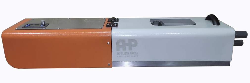
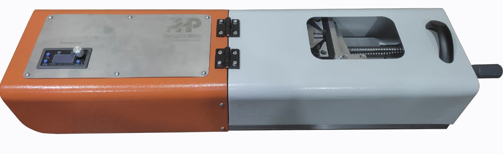
3. MACHINE COMPONENTS
Based on your machine type, main parts include:
- Base frame
- Specimen holder / clamping system
- Motorized cutting unit
- Cutting blade (notching tool)
- Depth adjustment mechanism
- Control panel (start/stop)
- Linear movement system (guide rails)
4. SAFETY INSTRUCTIONS ⚠️
MUST FOLLOW:
- Wear cut-resistant gloves
- Use safety glasses
- Ensure sample is firmly clamped
- Keep hands away from cutting area
NEVER:
- Touch blade during operation
- Operate with loose specimen
- Adjust settings while machine is running
⚠️ Danger: Sharp cutting blade + moving parts = injury risk
5. PRE-OPERATION CHECKLIST
Before each use:
Mechanical Check
- Blade is sharp and properly mounted
- Specimen holder is clean
- No debris on guide rails
Functional Check
- Power supply connected
- Motor runs smoothly
- Emergency stop works
6. OPERATING INSTRUCTIONS (DETAILED)
🔹 STEP 1 — SAMPLE PREPARATION
- Cut specimen to required FNCT dimensions
- Ensure surface is clean and smooth
- Mark notch position if required
6.1 Test specimen geometry
Typical test specimen geometries are given in Annex A. If other specimens are used, these shall be made
such that the ligament area is approximately 50 % of the total cross-sectional area of the specimen (see
Figure 4). This is to make sure that specimen failure will occur under the prescribed conditions. A “dog-bone” shaped specimen is easier to clamp, but a parallel-sided section of at least 15 mm on either side of the notch is required. The use of different test specimen geometries will give different results with the same polyethylene.
Comparisons between materials are only valid if the same specimen geometry and specimen preparation
technique are used.
A neutral-type nonylphenoxy-(ethyleneoxy)-ethanol detergent of the general formula shown below is required:
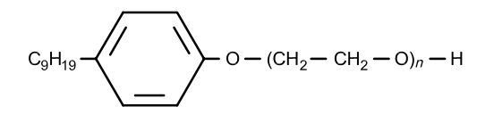
The value of n can be 10 or 11. Such detergents are suitable for use in testing at elevated temperatures and are sufficiently aggressive to produce failure in a reasonable timescale. A detergent with a value of n of 11 gives shorter failure times than one for which n = 10.
Using deionized water, prepare a sufficient quantity of a solution, of a concentration equivalent to 2 % by
mass of the detergent, to ensure complete immersion of the test specimens. Other surface-active agents may be used if specified in the relevant product standard or by agreement between the interested parties. If, for example, Igepal CO630 is used, its concentration and designation shall be clearly specified in the test report because the result may depend on the surfactant used.
NOTE The effect of a detergent on polyethylene varies with the density of the material. For lower-density PE, this can be more severe than if water or air alone is used.
Tests carried out using freshly made-up solutions of some detergents can give variable results, so the solution shall be “aged” for 14 days at the test temperature to ensure that the alcohol groups are converted to acid groups. This is said to improve the reproducibility of the results. The solution may continue to age, and it is suggested that a check be made after 2 500 h of use. Specimens of a control material can be tested in the solution to verify that there is no difference in activity.
6.2 Other environments
The FNCT is suitable for comparative testing of polyethylene test specimens with other chemicals, including distilled water. The test report shall contain full details of the identity, concentration and producer of the chemical used, as well as the designation of the polyethylene. Environments at higher temperatures, especially above 80 °C, can give different results due to absorption, chemical attack or crystalline changes in the polyethylene itself, and this shall be taken into consideration when carrying out the test.
7 Preparation of test specimens
7.1 Test specimen geometry
Typical test specimen geometries are given in Annex A. If other specimens are used, these shall be made
such that the ligament area is approximately 50 % of the total cross-sectional area of the specimen (see
Figure 4). This is to make sure that specimen failure will occur under the prescribed conditions. A “dog-bone” shaped specimen is easier to clamp, but a parallel-sided section of at least 15 mm on either side of the notch is required. The use of different test specimen geometries will give different results with the same polyethylene. Comparisons between materials are only valid if the same specimen geometry and specimen preparation technique are used.

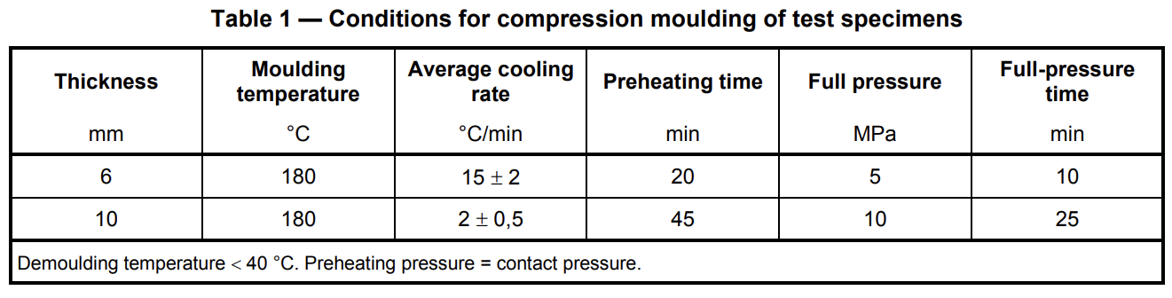
7.2 Test specimen preparation
Except when testing finished products, prepare test specimens from compression-moulded sheet.
ISO 1872-2:1993 (Subclause 3.3), ISO 11542-2:1998 (Table 1) and ISO 293 all give general guidelines for
moulding and cooling conditions. However, thick sheets require the use of the conditions specified in Table 1 below. The use of different moulding conditions will affect the results. Machine the test specimens to size from the moulded sheet in accordance with ISO 2818 at least 24 h after moulding. Trim the specimen edges of any remaining swarf left from machining. When comparing finished products, cut the test specimens from extruded or moulded goods in accordance with ISO 2818. Always check the relevant product standard for any further details.
If the material is a powder, it may be deemed necessary to calendar or compound the material prior to the compression-moulding step. It is essential to make sure that the powder is heat-stabilized when this is done.
7.3 Test specimen notching
Specimens shall be notched at room temperature. Due care shall be taken to avoid blunting the notch during this operation, e.g. avoid the use of excessive speed/force, as this will invalidate the results. If a razor blade is used, it shall be used for producing no more than a hundred notches. Whatever device is used for notching, the tolerance on the required notch depth is ± 0,1 mm.
NOTE Notch integrity may be checked microscopically.
7.4 Conditioning of test specimens
Normally, notched test specimens shall be stored at (23 ± 2) °C, although (27 ± 2) °C may be used in tropical countries. When they are required for use at other temperatures, they shall be conditioned in the environment at the test temperature for (10 ± 2) h after clamping in the loading apparatus and prior to loading.
🔹 STEP 2 — POSITIONING THE SAMPLE
- Place specimen in holder/clamp
- Align notch position with cutting blade
- Ensure correct orientation (centered)
✔ Proper alignment is critical for ISO compliance
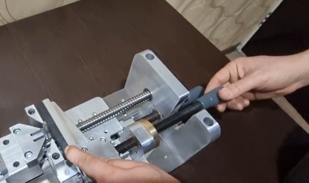
Set the end stopper position according to sample size. to have notching position in the middle length of the sample piece.
🔹 STEP 3 — CLAMPING
- Tighten clamping system securely
- Ensure:
- No movement
- No deformation of sample
⚠️ Loose sample = inaccurate notch
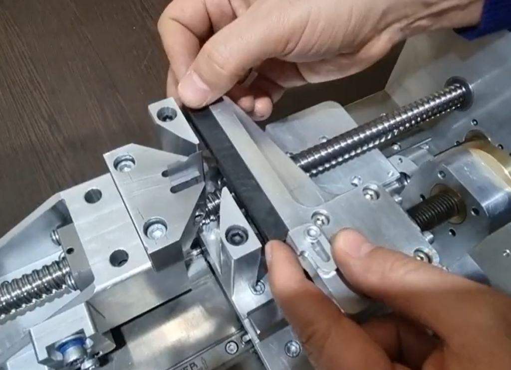
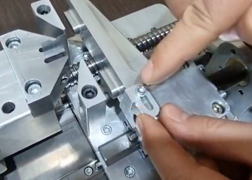
Place the sample piece in place and tighten it. be care full not to press sample much. turning the hand wheel as much as to hold the sample piece in place is enough.
Then place the zero position space in place to have the blade being in touch with the sample piece with no cutting. This will enable us to make the zero position for the blade.
After putting it in place, just use second hand wheel to bring the blade holder in contact with the spacer.
Now you can close cover and all is ready for making notch with controlled depth and travel speed of blade.
STARTING OPERATION
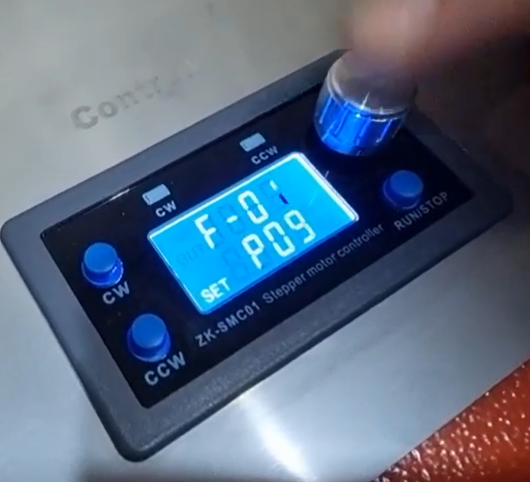
Press and hold the knob to above screen is appeared.
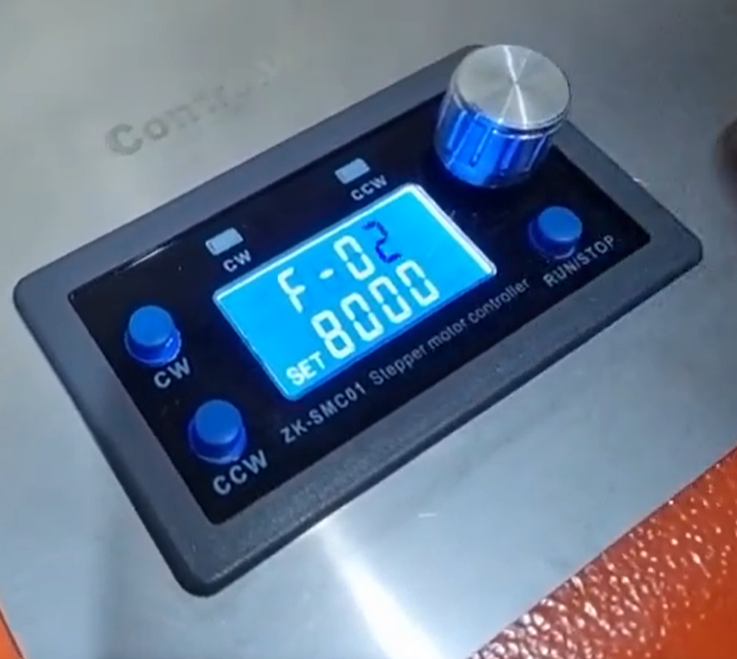
Turn the knob to “F-02” parameter is appeared. the value shown on the second row is the 5 times of depth of notch in terms on micron. Meaning if you divide this to 5 (8000/5=1600) will be 1600 micron in depth of notch. This “F-02” parameter is the forward movement of the blade after you set the zero point that is the touching point of the blade with sample piece.
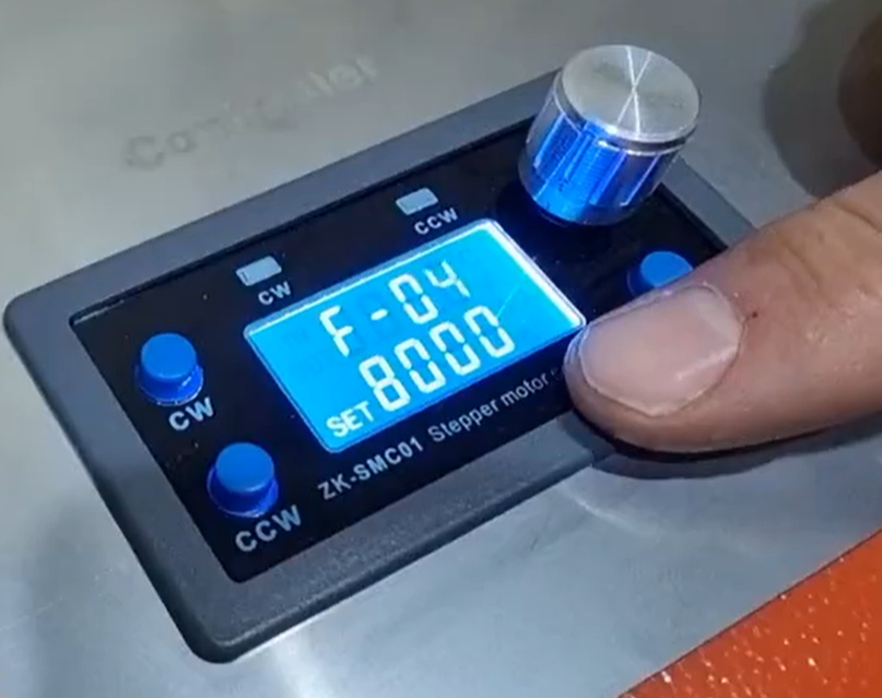
Turn the knob and get to the parameter “F-04” that is backward movement of the blade after froward movement is finished. Meaning when forward movement of the blade is done, it will be back to this much in terms of 5 time the micron. now it shows 8000 meaning 8000/5=1600 micron. Blade will have backward movement 1600 micron after it finished forward movement.
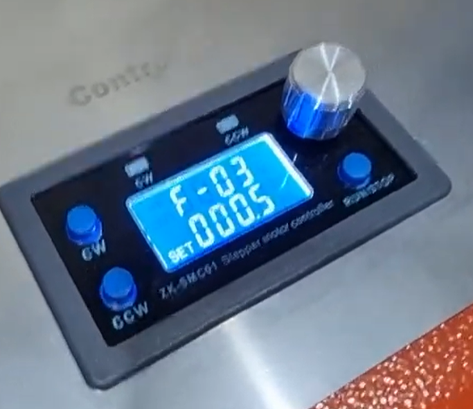
Forward movement speed of the blade will be set on the parameter “F-03”. The unit here is also have multiply factor of 5. It means when it shows 0.5 it means (0.5/5=0.1 turn/min) of the ball screw. When the machine ball screw has the pitch of 5mm, it mean that blade will move forward with the speed of 0.5mm/min, when you set the parameter F-03 to 0.5 turn/min.
Also you have same speed setting for the backward movement on the parameter F-05.
After you set all these 4 parameters you can push the knob and will will be saved and machine is ready to do the notch process.
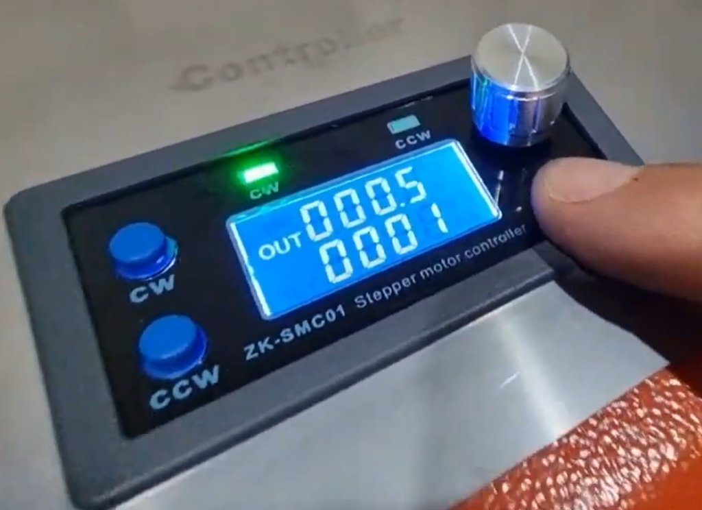
When you are on the main screen, you can start notching process by pushing the “Run/Stop” key. After press this key Led of “CW” will turn on and blade is going forward. After forward movement is finished the other led “CCW” will be on and blade is coming back to the original zero position where is starts the process.
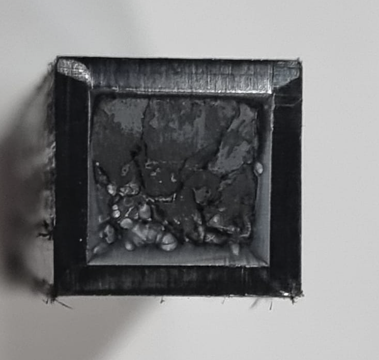
You will turn the sample to do the nothing on all 4 sides of the sample pieces. Be careful on sample placement position to be in center unless you will have unparallel notches on all 4 sides of the sample. Perfect notches will be as picture like below:
7. QUALITY CHECK (VERY IMPORTANT)
After cutting:
Check:
- Notch depth
- Notch shape
- Surface finish
✔ Must comply with ISO 16770
8. COMMON OPERATOR ERRORS
| Mistake | Result |
|---|---|
| Loose clamping | Uneven notch |
| Wrong depth setting | Invalid test |
| Dull blade | Rough surface |
| Misalignment | Off-center notch |
9. MAINTENANCE
Daily
- Clean machine
- Remove plastic debris
Weekly
- Check blade condition
- Inspect guide rails
Monthly
- Replace blade if worn
- Check alignment calibration
10. TROUBLESHOOTING
| Problem | Cause | Solution |
|---|---|---|
| Rough notch | Dull blade | Replace blade |
| Uneven cut | Misalignment | Re-align sample |
| Machine vibration | Loose parts | Tighten components |
| Incorrect depth | Misadjustment | Reset depth |
11. TECHNICAL NOTES
- Designed according to ISO 16770
- Ensures repeatable notch geometry
- Suitable for FNCT sample preparation
Any assistance needed, just contact on WhatsApp number: +905469180483 or email: info@ahp-makina.com