1 Scope
This document specifies two general test methods, Method A and Method B, for determining the impact strength of notched and unnotched specimens cut from thermoplastic pipes for the transport of liquid and gaseous media:
- Method A: test method for unnotched specimens cut from thermoplastics pipes for the transport of liquid and gaseous
media; - Method B: test method for notched specimens cut from thermoplastics pipes for the transport of liquids.
The selection of Method A or Method B shall be made in accordance with the relevant product standard.
This document does not establish a reference test method for determining pipe impact strength. ISO 3127, using a
falling mass, is the reference method. This document may be used for scientific research, material testing or pipe
inspection where measurements by the reference method are not possible.
The document applies to both isolated batches and continuously produced pipes
5 Test apparatus
5.1 Pendulum impact-testing machine
The principles, characteristics and verification of a suitable pendulum impact-testing machine shall conform to ISO 13802.
Where required, the machine may incorporate temperature-control equipment capable of maintaining the specified test temperature.
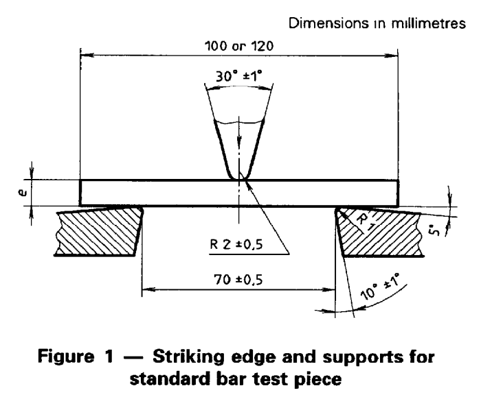
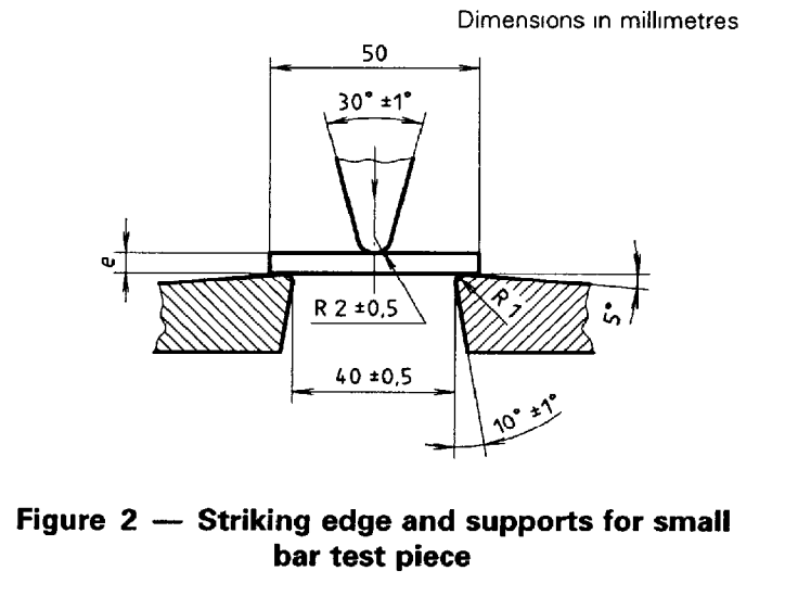
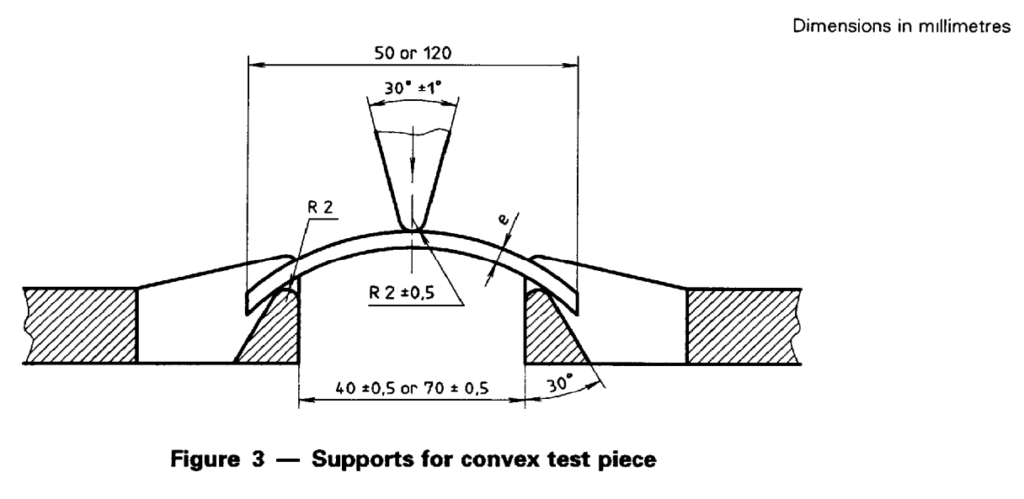
Method A: impact velocity 3.8 m/s; pendulums providing maximum impact energies of 15 J and 50 J; conical striker tip angle 30° ± 1° and tip radius (2.0 ± 0.5) mm; supports in accordance with Figures 1 and 2 for longitudinal specimens and Figure 3 for transverse specimens.
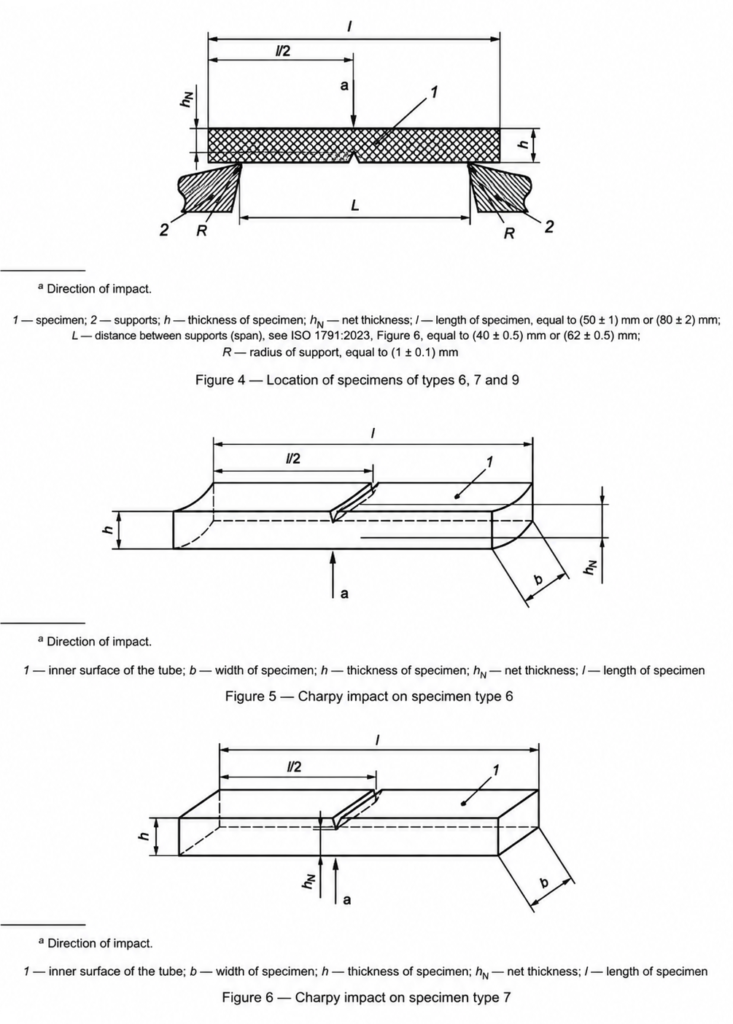
Method B: impact velocity 2.9 m/s; impact machine capable of providing absorbed energy between 10% and 80% of the available pendulum energy, with the same 30° ± 1° striker and (2.0 ± 0.5) mm tip radius; supports in accordance with Figure 4.
5.2 Micrometers and gauges
Micrometers and gauges capable of measuring the principal specimen dimensions to 0.02 mm are required. For the remaining thickness hN of notched specimens, the micrometer measuring tip shall have a profile corresponding to the notch type.
5.3 Conditioning equipment
A thermostatically controlled enclosure or liquid bath capable of bringing the specimens to the specified temperature Tc . Any bath liquid used shall not adversely affect the physical properties of the specimens.
5.4 Temperature-measuring equipment Equipment
capable of verifying the specified temperature to within ±0.5 °C.
6 Test specimens
6.1 Preparation
Specimens shall be cut from the pipe in accordance with ISO 2818 and 6.2.1 (Method A) or 6.2.2 (Method B), as applicable. Any surface that contacts the supports or the pendulum at impact shall be smooth and free from burrs. Chamfering shall be avoided.
6.2 Cutting and dimensions
6.2.1 Method A
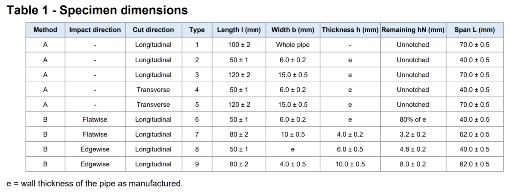
For pipes with nominal outside diameter dn up to 25 mm, each specimen shall be a pipe length (100 ± 2) mm, specimen type 1.
For 25 mm ≤ dn < 75 mm, each specimen shall be cut longitudinally and shall conform to type 2 or type 3 dimensions.
For 75 mm ≤ dn < 160 mm, specimens shall be cut both longitudinally and transversely. Longitudinal specimens shall be type 2 or 3; transverse specimens shall be type 4.
For dn ≥ 160 mm, longitudinal specimens shall be type 2 or 3, and transverse specimens shall be type 4 or 5.
6.2.2 Method B
Each notched specimen shall be cut from the pipe in accordance with 6.1 and shall conform to one of the specimen types in Table 1. For types 7 and 9, both surfaces shall be machined to the dimensions specified. A type A notch shall then be made in accordance with ISO 179-1: notch angle 45° ± 1° and notch-tip radius (0.25 ± 0.05) mm. The notch shall be located at the specimen center within ±1 mm.
a) Flatwise impact, en≤6 mm: type 6, longitudinally cut, notch on the original inner pipe surface.
b) Flatwise impact, en>6 mm: type 7, longitudinally cut, notch on the machined inner surface.
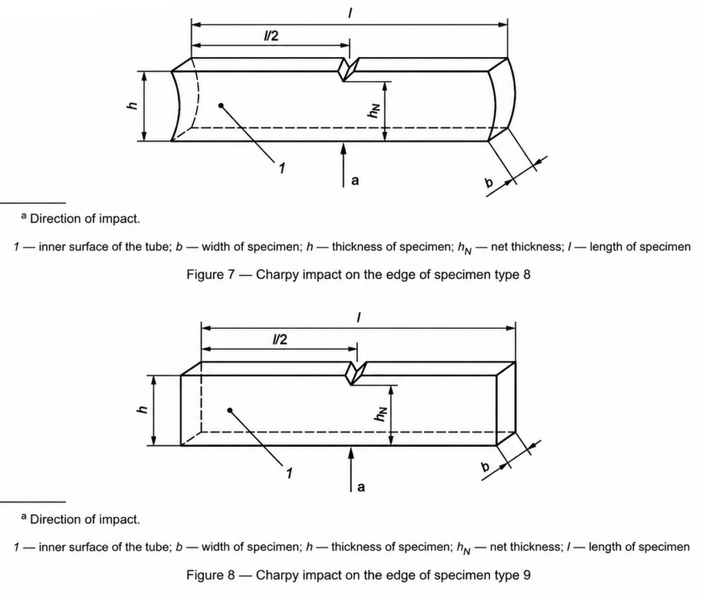
c) Edgewise impact, en≤6 mm: type 8, longitudinally cut, notch on a surface cut from the pipe.
d) Edgewise impact, en>6 mm: type 9, longitudinally cut, notch on a surface cut from the pipe.