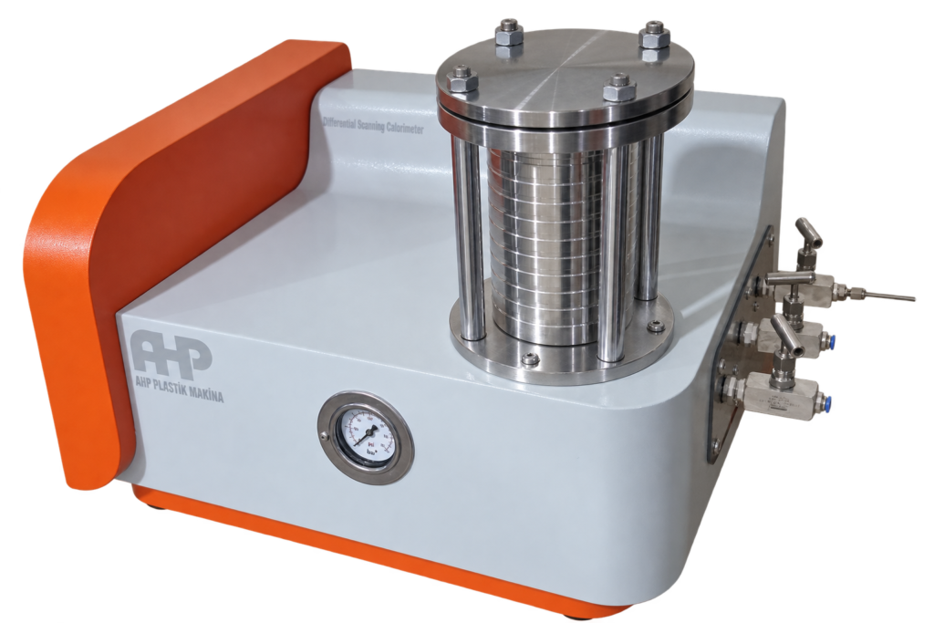
This section describes the correct installation and connection of the external utilities required for operation of the AHP HPOIT / DSC Tester, including:
Oxygen (O₂) gas supply
Nitrogen (N₂) gas supply
Nitrogen rotameter connections
Drain / cooling line
Electrical power connection
USB communication connection
High-pressure gas cylinder and regulator safety
These instructions shall be read completely before connecting or operating the instrument.
WARNING — HIGH-PRESSURE GAS
Compressed gas cylinders contain a large amount of stored energy. Incorrect handling, unsuitable regulators, damaged fittings, contamination, or excessive pressure can cause serious injury, fire, equipment damage, or explosion.
2. Instrument Gas and Drain Connections
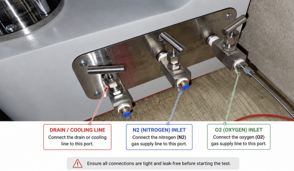
The three connections on the instrument are arranged as follows when viewing the connection panel from the front:
Left connection: DRAIN / COOLING LINE
Center connection: N₂ — NITROGEN GAS INLET
Right connection: O₂ — OXYGEN GAS INLET
Before starting a test, ensure that all tubing, fittings, valves, and connectors are correctly installed and leak-free.
2.1 Oxygen Inlet
Connect the oxygen supply line to the O₂ inlet located on the right-hand side of the gas connection panel.
The oxygen line must only contain components suitable for oxygen service.
2.2 Nitrogen Inlet
Connect the nitrogen supply from the rotameter outlet to the N₂ inlet located in the center of the connection panel. for the high pressure OIT testing you don’t need to connect N2 connection.
2.3 Drain / Cooling Connection
Connect the required drain or cooling line to the left-hand connection marked Drain / Cooling. the drain is for the time of using of the machine for high pressure applications. cooling is for the time of using the machine for standard pressure OIT measurement and is used for rapid cooling of the chamber for the next test to be started fast. be noted to use dry air when you want to use cooling function unless you will damage the heater and furnace with wet cooling air.
Note: when you are using high pressure OIT testing you don’t need to connect N2 gas to the machine.
Route the line so that it is not kinked, restricted, crushed, or exposed to mechanical damage.
3. High-Pressure Oxygen Supply
Oxygen is used as a reactive gas during oxidation-related DSC / OIT measurements. Oxygen does not burn by itself, but it strongly supports combustion and can make normally combustible materials ignite more easily and burn much more intensely.
Pure oxygen at high pressure requires special precautions.
3.1 Oxygen Cylinder
Use only a correctly identified, inspected, approved oxygen cylinder supplied by an authorized industrial-gas supplier.
The cylinder shall:
Be maintained in good physical condition.
Have a serviceable cylinder valve.
Be kept upright during use.
Be mechanically secured with a suitable chain, strap, or cylinder restraint.
Be protected against falling, impact, excessive heat, and mechanical damage.
Be positioned in a well-ventilated area.
Be kept away from ignition sources, sparks, flames, hot surfaces, combustible materials, oil, and grease.
Never roll, drag, drop, strike, or use a compressed-gas cylinder as a support.
The cylinder valve shall remain closed whenever the gas supply is not required.
4. Oxygen Regulator Requirements
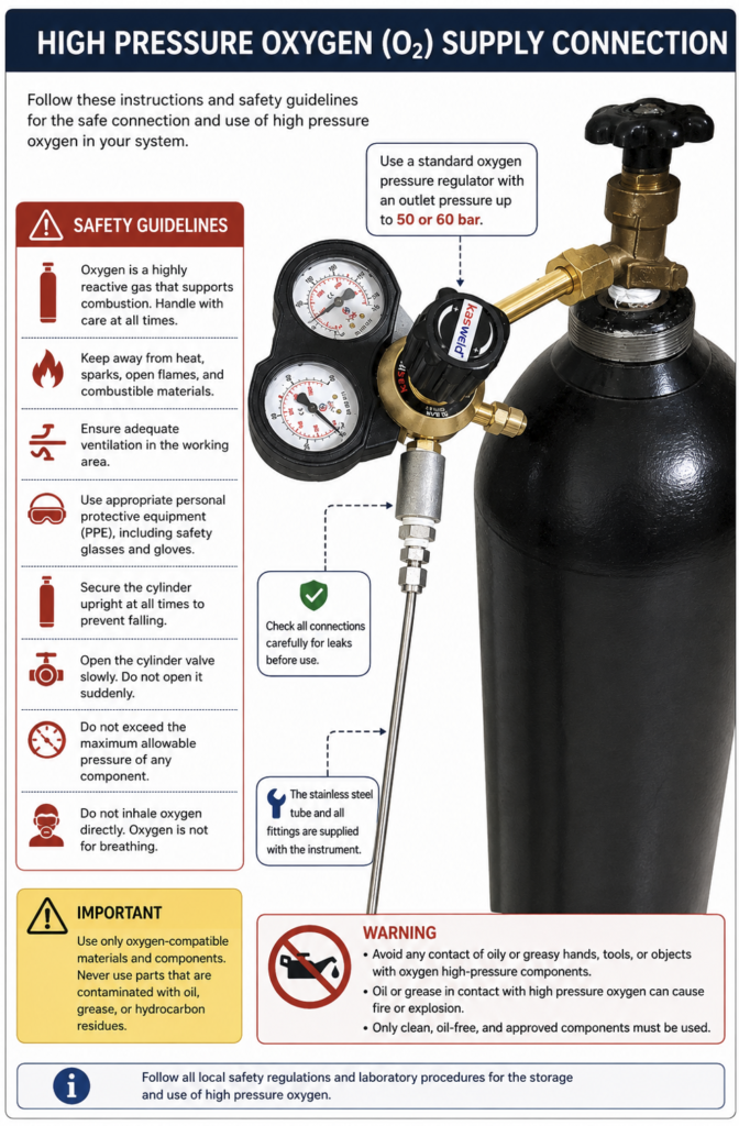
A pressure regulator specifically approved for oxygen service shall be installed between the high-pressure oxygen cylinder and the instrument.
Use a standard oxygen pressure regulator having a suitable high-pressure inlet rating (like 350 bars) for the selected cylinder and an outlet range/rating up to approximately 50–60 bar, as applicable to the regulator supplied or specified for the system.
IMPORTANT
The 50–60 bar value refers to the regulator’s capability/range and does not mean that the instrument should be operated at 50–60 bar. the instrument is suitable for pressure up to 35 bar only for this kind of machine.
The actual regulator delivery pressure shall always be adjusted only to the pressure required by the instrument or validated test procedure.
Never exceed the maximum allowable working pressure of the instrument, tubing, fittings, rotameter, valves, or any other downstream component.
The regulator shall:
Be designed and certified for oxygen service.
Be clean and free from oil, grease, dirt, hydrocarbons, and other contamination.
Have correctly operating pressure gauges.
Have compatible inlet and outlet connections.
Be in good mechanical condition.
Never be modified or repaired by unauthorized personnel.
The pressure-adjustment knob should be released or backed off before opening the cylinder valve so that unwanted outlet pressure is not applied suddenly.
5. Critical Oxygen Cleanliness Requirements
WARNING — NO OIL OR GREASE
Never allow oil, grease, lubricants, hydrocarbon residues, oily tools, greasy gloves, or oily hands to contact any component used in the high-pressure oxygen system.
This applies particularly to:
Oxygen cylinder valve
Regulator inlet
Regulator outlet
Pressure gauges
Oxygen tubing
Compression fittings
Valves
Instrument O₂ inlet
Adaptors
Sealing surfaces
Tools used during assembly
Oil or grease can react violently with high-pressure oxygen and may cause ignition, fire, or explosion.
Only clean components approved for oxygen service shall be used.
If oxygen-service equipment becomes contaminated, do not attempt to clean it using normal workshop solvents or methods. Remove it from service and have it cleaned or replaced according to an approved oxygen-cleaning procedure.
6. Oxygen Tubing and Fittings
The stainless-steel oxygen tube, associated fittings, and oxygen regulator are supplied with the instrument according to the supplied system configuration.
Use these supplied components unless an equivalent replacement has been specifically approved for oxygen service.
Do not substitute:
General-purpose pneumatic tubing
Unapproved plastic tubing
Improvised adapters
Greased fittings
Unknown thread sealants
Components with an inadequate pressure rating
All joints must be mechanically secure and compatible with oxygen service.
Where a sealing material is required, use only a sealant explicitly approved for oxygen service and suitable for the specific connection type.
7. Correct Oxygen Connection Procedure
The recommended connection sequence is:
Oxygen Cylinder → Oxygen Pressure Regulator → Stainless-Steel Gas Line → Instrument O₂ Inlet
Step 1 — Prepare the System
Ensure that:
The instrument is not running.
The oxygen cylinder valve is closed.
The regulator adjusting knob is released.
The instrument O₂ valve is closed.
All oxygen components are visibly clean and oil-free.
Step 2 — Secure the Cylinder
Place the oxygen cylinder vertically and secure it against falling or movement.
Do not install a regulator on an unsecured cylinder.
Step 3 — Inspect the Regulator
Confirm that:
The regulator is intended for oxygen.
The inlet connection matches the cylinder valve.
The regulator and gauges are undamaged.
Connections are clean.
No oil or grease is present.
The regulator adjustment is at minimum / zero delivery pressure before pressurization.
Step 4 — Install the Regulator
Attach the regulator to the oxygen cylinder using the correct connection provided for the cylinder.
Do not force incompatible threads.
Do not use makeshift adapters.
Do not use excessive tightening force.
Step 5 — Connect the Stainless-Steel Oxygen Line
Connect the supplied stainless-steel gas line to the regulator outlet.
Tighten the fitting using the correct wrench while supporting the mating fitting where necessary to prevent twisting of the regulator.
Step 6 — Connect the Instrument
Connect the other end of the stainless-steel line to the O₂ inlet on the right-hand side of the instrument gas panel.
Ensure that the fitting is correctly seated and tightened.
Step 7 — Pressurize Slowly
Stand in a safe position and slowly open the oxygen cylinder valve.
Never open a high-pressure oxygen cylinder valve suddenly.
Increase regulator outlet pressure gradually to the required operating value.
Step 8 — Leak Test
Before starting a DSC / OIT test, check every oxygen connection for leakage using an oxygen-compatible leak-detection method.
Inspect:
Cylinder-to-regulator connection
Regulator body and outlet
Stainless-steel tube fittings
Instrument O₂ inlet
Associated valves
Never use a flame to locate a gas leak.
If leakage is detected:
Close the cylinder valve immediately.
Stop the test.
Ventilate the area.
Depressurize the system safely.
Correct the leak before restarting.
8. Oxygen Safety During Operation
During oxygen operation:
Maintain adequate room ventilation.
Keep all ignition sources away.
Do not smoke near the oxygen system.
Keep combustible materials away from the cylinder and connections.
Do not direct oxygen toward clothing, personnel, equipment, or work surfaces.
Never use oxygen as compressed air for cleaning.
Never inhale oxygen directly.
Do not touch oxygen components with oily or greasy hands or gloves.
Never loosen a fitting while the line is pressurized.
Do not exceed the pressure rating of any component.
Keep the cylinder valve accessible at all times.
Protect tubing from impact and mechanical damage.
Do not leave a pressurized system unattended for unnecessary periods.
Appropriate laboratory PPE should be used, including safety glasses and suitable clean gloves.
9. Nitrogen Supply and Rotameter
Nitrogen flow to the instrument is controlled using the supplied external rotameter. This is only used in standard pressure OIT measurement applications. You don’t need it when you are using high pressure OIT measurement device.
The rotameter shall be installed in an upright position so that its flow indication operates correctly.
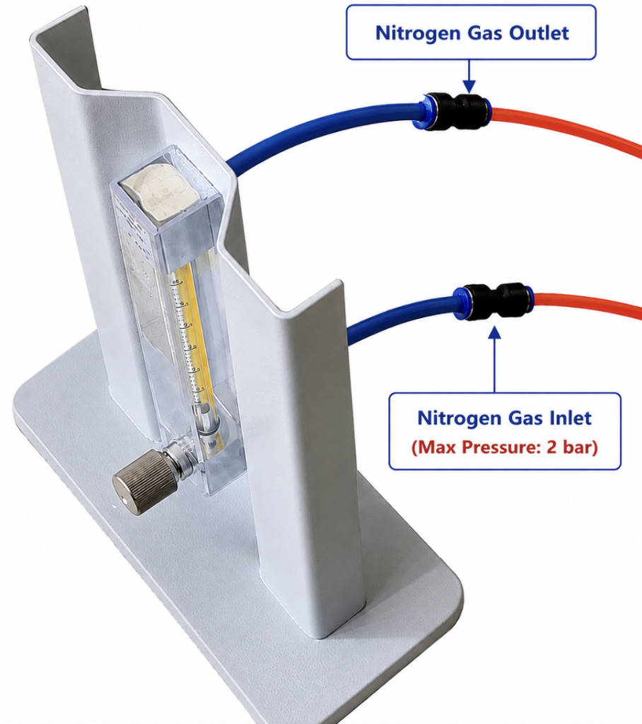
The two rotameter hose connections are:
Lower Hose Connection
NITROGEN GAS INLET Maximum Inlet Pressure: 2 bar
Connect the regulated nitrogen supply to this lower inlet.
CAUTION
Do not apply more than 2 bar to the rotameter inlet.
Excessive pressure may damage the rotameter, tubing, connectors, or associated components.
Upper Hose Connection
NITROGEN GAS OUTLET
Connect the upper rotameter outlet to the N₂ inlet located in the center of the instrument gas connection panel.
Use a suitable regulator compatible with the nitrogen cylinder.
Before supplying gas to the rotameter:
Close or reduce the regulator outlet pressure.
Confirm that the rotameter control valve is in a safe position.
Open the nitrogen cylinder valve slowly.
Gradually adjust the regulator.
Ensure the pressure entering the rotameter remains below 2 bar.
Adjust the rotameter flow with its control knob to the value required by the test method.
The required flow rate shall be set according to the applicable DSC / OIT method and the test parameters entered in the software.
11. Rotameter Operating Precautions
For correct flow indication:
Keep the rotameter vertical during use.
Make sure the flow direction is correct.
Connect the gas supply to the lower Nitrogen Gas Inlet.
Connect the upper Nitrogen Gas Outlet to the instrument.
Do not exceed 2 bar inlet pressure.
Do not allow the tubing to become kinked.
Make sure push-fit connectors are fully engaged.
Check hoses regularly for cracking, damage, or hardening.
Do not operate a cracked or damaged flow tube.
Adjust the flow slowly.
Do not apply sudden pressure to the rotameter.
12. Drain / Cooling Line Connection
The Drain / Cooling connection is located on the left-hand side of the instrument gas panel.
Connect the drain/cooling hose or line securely to this port.
Before operation:
Confirm correct hose routing.
Ensure that the line is not blocked.
Avoid sharp bends and kinks.
Make sure the discharge end is positioned safely.
Verify that the line cannot move or disconnect during operation.
If the cooling circuit is used, ensure that the associated cooling system is correctly installed before enabling the Drain-Cooling function in the software.
note1: when you are using high pressure mode, you don’t need to connect the Drain/Cooling line to anywhere. leave it open as it is.
note2: when you are using standard low pressure mode, you will connect this to the rotameter inlet line to adjust the N2 gas flow that comes out of the chamber
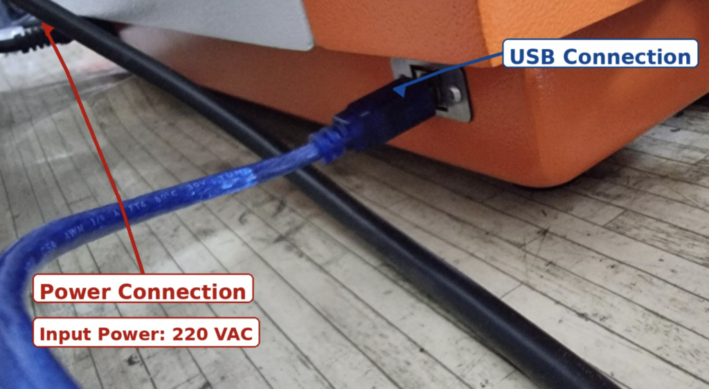
13. Electrical Power Connection
The instrument requires:
Input Power: 220 VAC-single phase
The power connector and USB communication connector are separate connections.
When viewed from the rear of the instrument:
The black power cable connection is located on the left side / opposite side from the USB connection.
The USB connection is located on the right side.
Power Connection Procedure
Before connecting electrical power:
Make sure the instrument is switched OFF.
Verify that the available mains supply is 220 VAC and compatible with the instrument nameplate.
Use the supplied or approved power cable.
Connect the black power cable securely to the instrument power inlet.
Connect the other end to a correctly installed protective-earth / grounded electrical outlet.
Ensure that the cable cannot be accidentally pulled or damaged.
WARNING — ELECTRICAL SAFETY
Never operate the instrument using an ungrounded power supply.
Do not connect or disconnect the power cable with wet hands.
Do not use damaged cables, plugs, or electrical outlets.
14. USB Communication Connection
The USB cable provides communication between the instrument and the computer running the AHP DSC software.
The USB port is independent from the 220 VAC power connection.
To connect:
Connect the blue USB cable to the USB port on the rear/right side of the instrument.
Connect the other end to the computer.
Ensure that both connectors are fully inserted.
Route the USB cable away from hot surfaces, sharp edges, moving parts, and high-current electrical cables where practical.
Start the software and confirm that the correct communication port is selected.
Do not pull the USB cable by the cable itself when disconnecting it. Hold the connector body.
15. Pre-Start Inspection
Before every test, verify the following:
Oxygen cylinder is correctly identified and securely restrained.
Oxygen regulator is approved for oxygen service.
Oxygen regulator, valves, tubing, fittings, hands, gloves, and tools are free from oil and grease.
Stainless-steel oxygen line is correctly installed.
O₂ line is connected to the right-hand O₂ inlet.
N₂ line is connected to the center N₂ inlet.
Drain / Cooling line is connected to the left-hand port.
Rotameter lower connection is used as Nitrogen Gas Inlet.
Rotameter upper connection is used as Nitrogen Gas Outlet.
Rotameter inlet pressure does not exceed 2 bar.
All gas connections have been checked for leaks.
No damaged tubing or fittings are present.
Drain/cooling line is unobstructed.
Power cable is correctly connected.
Supply voltage is 220 VAC.
Protective earth/ground is available.
USB cable is correctly connected.
Working area is adequately ventilated.
No ignition sources or combustible contamination are present near the oxygen supply.
Do not start the instrument unless all checks are satisfactory.
16. Recommended Start-Up Sequence
After completing all mechanical and electrical connections:
Secure and inspect all gas cylinders.
Verify that all instrument gas valves are initially in the required safe position.
Connect the nitrogen system and rotameter.
Connect the oxygen cylinder, regulator, stainless-steel tube, and O₂ inlet.
Connect the drain/cooling line.
Leak-test all gas connections.
Connect the USB cable to the computer.
Connect the instrument to the 220 VAC power supply.
Switch on the instrument.
Start the AHP DSC software.
Verify communication.
Enter the required test parameters.
Establish the required nitrogen purge.
Confirm stable gas flow.
Introduce oxygen only when required by the programmed OIT test sequence.
17. Never open the lid of the furnace before releasing the tapped pressure inside furnace using drain needle valve
18. High-Pressure Gas Cylinder General Safety
The following rules apply to oxygen, nitrogen, and other compressed-gas cylinders:
Use only correctly identified cylinders.
Check cylinder condition before use.
Secure cylinders against falling.
Keep valve protection caps installed during transport where applicable.
Use a suitable cylinder trolley for transport.
Never lift a cylinder by the regulator or valve.
Never drop or deliberately strike cylinders.
Do not expose cylinders to excessive heat.
Keep cylinders in a ventilated location.
Protect valves and regulators from physical damage.
Use only regulators intended for the specific gas.
Never force incompatible connections.
Never modify cylinder valves, regulators, or safety devices.
Never attempt to refill a cylinder yourself.
Close cylinder valves after use.
Report damaged or malfunctioning cylinders to the gas supplier.
19. Special Warning for High-Pressure Oxygen
DANGER — OXYGEN FIRE / EXPLOSION HAZARD
High-pressure oxygen can react violently with contamination and incompatible materials.
The following rules are mandatory:
NO OIL. NO GREASE. NO OILY HANDS. NO GREASY TOOLS. NO UNAPPROVED LUBRICANTS. NO UNAPPROVED SEALANTS.
Keep oxygen equipment away from:
Oil
Grease
Petroleum products
Solvents not approved for oxygen service
Open flames
Sparks
Smoking materials
Hot surfaces
Combustible waste
Contaminated gloves and tools
Only components explicitly suitable for oxygen service may be installed in the oxygen circuit.
If there is any doubt regarding the cleanliness or compatibility of a component, do not use it.
20. Leak or Emergency Condition
If an oxygen or nitrogen leak is suspected:
Do not create sparks or flame
Stop the test if this can be done safely.
Close the cylinder valve if accessible and safe.
Isolate the gas supply.
Ventilate the area.
Keep personnel away from the affected location.
Do not resume operation until the leak has been found and corrected.
If an oxygen system becomes contaminated with oil or grease, remove it from service immediately.
In the event of fire involving an oxygen system, follow the site’s emergency response procedure and local fire-safety requirements.
21. Maintenance
Periodically inspect:
Gas regulators
Pressure gauges
Cylinder connections
Stainless-steel tubing
Compression fittings
Instrument gas valves
Push-fit connectors
Rotameter body and flow tube
Flexible hoses
Drain/cooling line
USB cable
Power cable and plug
Replace damaged components before further operation.
Oxygen-service parts shall be maintained in a clean condition and protected from contamination during maintenance and storage.
Only trained and authorized personnel shall perform maintenance on pressurized gas systems or oxygen-service components.
22. Final Safety Statement
Safe operation of the HPOIT / DSC Tester depends on correct installation of the gas, drain, electrical, and communication connections.
Particular attention shall be given to the oxygen circuit because pure oxygen under pressure presents a significantly increased fire hazard.
Always:
Use oxygen-approved equipment.
Keep oxygen components completely free from oil and grease.
Secure high-pressure cylinders.
Open cylinder valves slowly.
Verify all connections for leakage.
Respect the pressure rating of every component.
Never exceed 2 bar at the nitrogen rotameter inlet.
Use a grounded 220 VAC electrical supply.
Follow applicable local regulations, laboratory safety procedures, and compressed-gas requirements.
If any connection, pressure rating, component compatibility, or safety condition is uncertain, do not operate the instrument until the condition has been verified by qualified personnel.