4. Summary of Test Method
4.1 The specimen to be tested and the corresponding reference material are heated from room temperature at a constant rate in a non-purging, high-pressure oxygen environment at a defined pressure. When the specified temperature has been reached, the specimen is then held at that temperature until the oxidative reaction is displayed on the thermal curve. The OIT is the time interval from the start of the temperature program test to the onset of the oxidative reaction.
4.2 In this procedure, an elevated pressure of oxygen is used to accelerate the reaction and to reduce analysis time.
4.3 Unless otherwise specified, the temperature used in this test method shall be 150°C, and the chamber pressure is to be maintained at 3.4 MPa (500 psi) using a constant volume test condition.
5. Significance and Use
5.1 The oxidative induction time is a characteristic of a compounded polyolefin product that is dependent not only on the type and amount of additives present, but also on the type of resin. In well-behaved systems, this test method can be used as a quality control measure to monitor the stabilization in geosynthetics as received from a supplier.
5.2 When this test method is used to compare different geomembrane formulations containing different antioxidant packages, then those results shall be considered valid only at the temperature of test.
5.3 This test method is intended as an geosynthetic test. Use of the OIT value to estimate the lifetime of the geomembrane from which the test specimen is taken is not addressed nor shall it be used for this purpose.
5.3.1 The OIT measurement is an accelerated thermal aging test and, as such, interpretation of resulting data may be misleading if done by an inexperienced operator. Caution should be exercised in data interpretation since oxidation reaction kinetics are a function of temperature and the properties of the additives contained in the geosynthetic sample. For example, OIT values are often used to select optimum resin formulations. Certain antioxidants, however, may generate poor OIT results even though they may be adequate at their intended use temperature and vice versa.
5.4 This test method can be used for other purposes such as manufacturing control and research and development.
5.5 Oxidation induction time is strongly dependent upon test temperature and the partial pressure of oxygen. The higher the test temperature or the oxygen partial pressure, or both, the shorter the oxidation induction time.
5.5.1 The use of high test temperature, however, may have deleterious effects. The first of these is the potential volatilization of additive packages used to stabilize the test materials.
The second is the potential for the influence of chemical mechanisms which are not significant at end-use operation conditions.
5.5.2 This test method uses high oxygen pressure to accelerate the test period while making use of lower test temperatures to protect additive packages.
5.6 The results from this test method may or may not correlate with those obtained by other OIT measurements such as Test Method D 3895 or Test Methods D 4565.
6. Apparatus
6.1 Differential Scanning Calorimeter—Thermal analysis equipment capable of heating rates up to 20 6 1°C/min and of automatically recording the differential heat flow between the test sample and a reference sample is necessary. The equipment must be capable of measuring sample temperature to 61°C while maintaining a set temperature to 60.5°C.
NOTE 1—Modern computer-based instrumentation equipped with “isotrack” modes provide adequate specimen temperature control.
6.2 Data Presentation Device—A printer, plotter, recorder, or other recording output device capable of displaying heat flow on the Y-axis versus time on the X-axis as output signals from differential scanning calorimeters in 6.1.
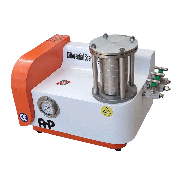
6.3 High-Pressure DSC Cell—A unit capable of maintaining pressure up to 3.4 MPa (500 psig). The system shall be equipped with a pressure gage to monitor the internal pressure of the cell to permit manual release of pressure to maintain desired level.
NOTE 2—The gage shall be accurate to 2 % at 3.4 MPa (500 psig). NOTE 3—All pressures in this test method are indicated relative to
atmosphere pressure—that is, they are “gage” pressures.
6.4 High-Pressure Oxygen Cylinder Regulator—A pressure regulator capable of regulating a pressure up to 5.5 MPa (800 psi). The outlet of the cylinder is to be linked to the high-pressure cell using a clean stainless steel tube.
6.5 Analytical Balance, 0.1-mg sensitivity.
6.6 Specimen Holders, degreased aluminum pans, 6.0 to
7.0-mm diameter.
6.7 Core Hole Borer, cork borer or arch punch producing
6.3-mm (0.25-in.) disks.
7. Reagents and Materials
7.1 All chemical reagents used in this test method shall be analytical grade unless otherwise specified.
7.2 Hexane or Acetone, for cleaning specimen pans and stainless steel tubing, see 8.2 and 8.3.
7.3 Indium (99.999 % Purity), for calibration purposes, see 9.1.
7.4 Oxygen, purity >99.5 % for the test atmosphere.
8. Precautions
8.1 Oxygen is a strong oxidizer that vigorously accelerates combustion. Keep oil and grease away from equipment using or containing oxygen.
8.2 The stainless steel tube connecting the high-pressure cell to the oxygen cylinder must be thoroughly cleaned by hexane (or acetone) and then dried before being connected to the cell.
8.3 All specimen holders should be cleaned by washing with hexane (or acetone) and then drying before being used in the test.
8.4 The use of pressurized oxygen requires appropriate and careful handling procedures. The user of this test method shall be familiar with the precautions described in Guide G88.
9. Sampling
9.1 Using a bore hole cutter, cork borer, or punch, cut several 6.3-mm (0.25-in.) round specimen from the geosynthetic test sample.
9.2 Compression mold these assembled parts into a uniform plaque to a thickness of 0.25 mm (10 mil) (see Practice D 4703).
NOTE 4—The temperature at which molding takes place may be at or above the test temperature of this test method. Prolonged exposure to air at these temperatures may induce a negative bias into OIT measurement. Molding should be performed at as low a temperature and as quickly as possible to minimized this bias.
9.3 Cut test specimens from the plaque using a 6.3-mm
(0.25-in.) bore hole cutter or punch.
10. Calibration
10.1 Using Test Method E 967, temperature calibrate the differential scanning calorimeter using indium metal and a heating rate of 1°C/min from 145 to 165°C.
10.1.1 Perform the calibration step at least once a month or whenever changes have occurred in the experimental setup.
11. Procedure
NOTE 5—Procedures for preparing the test specimen may be different for different polyolefin geosynthetic products, for example, geomembranes, geonets, geogrids, or geotextiles.
11.1 Prepare a specimen with a mass of 5 6 1 mg.
11.2 Place the weighed specimen into the cleaned specimen pan.
11.3 Place the specimen and reference pans into the cell.
NOTE 6—Open pans are used in this test method.
11.4 Secure the top plate of the test chamber and tighten the cell system.
11.5 Terminate the test after the oxidative exothermal peak has passed through its maximum value.
11.6 After the test is completed, slowly release the pressure by gradually opening the pressure release valve.
NOTE 7—It usually takes 30 to 60 s to completely release the pressure.
11.7 Clean the instrument cell by thermal desorption after every three to four tests to remove any accumulated organic matter so as to ensure safe operation.
NOTE 8—The DSC cell should be cleaned by holding the cell at a temperature of 400°C for 3 min under air or oxygen atmosphere.
12. Analysis Response
12.1 Plot the data with the heat flow signal on the y-axis, versus time on the x-axis.
12.2 Determine the value for OIT in the following manner:
12.2.1 Plot data with a y-axis sensitivity sufficient to show the full oxidative exotherm. A full-scale sensitivity of 5 W/g is usually adequate.
12.2.2 Extend the horizontal baseline generated prior to the onset to oxidation.
NOTE 9—For the oxidation exotherm containing a small shoulder peak at the beginning of oxidation, a sigmoidal baseline may be more appropriate than the straight baseline.
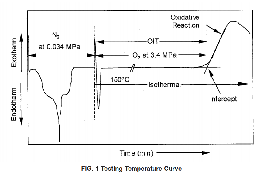
12.2.3 Draw a tangent at the inflection point of the exothermic peak and extend this tangent to intersect with the baseline.
12.2.4 The time at the intersection, measured from the initiation of the temperature program from ambient temperature is the onset of oxidative degradation and is taken as the OIT value.
12.2.5 Measure the OIT as shown in Fig. 1.
12.3 Report the OIT for a single specimen.
NOTE 10—If replicate tests are required by the parties involved, a mean value shall be calculated as being representative of the material being evaluated.


