5 Apparatus
5.1 Test machine
The principles, characteristics and verification of suitable test machines are detailed in ISO 13802. ISO 13802 describes partial verification and full verification. In the case of full verification, some items are difficult to verify when the apparatus is assembled. Such verifications are assumed to be incumbent on the manufacturer.
5.2 Micrometers and gauges
Micrometers and gauges capable of measuring the essential dimensions of test specimens to an accuracy of 0,02 mm are required. For measuring the dimension bN of notched specimens, the micrometer shall have a spindle with a measuring tip having a suitable profile to fit the shape of the notch.
6 Test specimens
6.1 Preparation
6.1.1 Moulding and extrusion compounds
Specimens shall be prepared in accordance with the relevant material specification. The specimens shall be either directly compression moulded in accordance with ISO 293 or ISO 295 or injection moulded from the material in accordance with ISO 294-1, ISO 294-3 or ISO 10724-1, as appropriate, or machined in accordance with ISO 2818 from sheet that has been compression or injection moulded from the compound. Type 1 specimens may be cut from multipurpose test specimens complying with ISO 3167, type A.
6.1.2 Sheets
Specimens shall be machined from sheets in accordance with ISO 2818.
6.1.3 Long-fibre-reinforced materials A panel shall be prepared in accordance with ISO 1268-11 or another specified or agreed upon preparation procedure. Specimens shall be machined in accordance with ISO 2818.
6.1.4 Checking
The specimens shall be free of twist and shall have mutually perpendicular parallel surfaces. The surfaces
and edges shall be free from scratches, pits, sink marks and flash.
The specimens shall be checked for conformity with these requirements by visual observation against
straightedges, set squares and flat plates, and by measuring with micrometer callipers. Specimens showing measurable or observable departure from one or more of these requirements shall be rejected or machined to proper size and shape before testing.
6.1.5 Notching
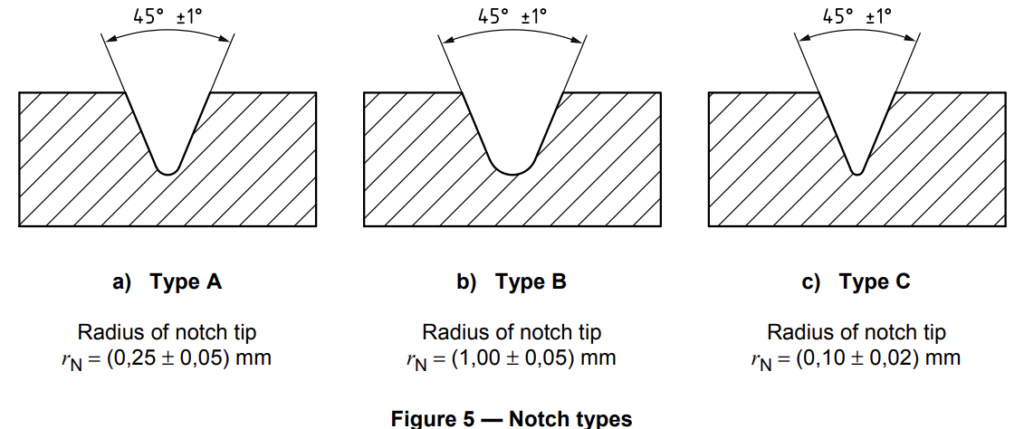
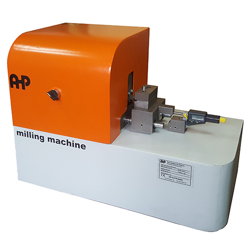
6.1.5.1 Machined notches shall be prepared in accordance with ISO 2818. The profile of the cutting tooth
shall be such as to produce in the specimen a notch of the contour and depth shown in Figure 5, at right
angles to its principal axes (see Note).
NOTE The radius of the notch tip can be measured by the method given in Annex C. 6.1.5.2 Specimens with moulded-in notches may be used if specified for the material being tested (see Note).
NOTE Specimens with moulded-in notches do not give results comparable to those obtained from specimens with machined notches.
6.3 Shape and dimensions
6.3.1 Materials not exhibiting interlaminar shear fracture
6.3.1.1 Moulding and extrusion compounds
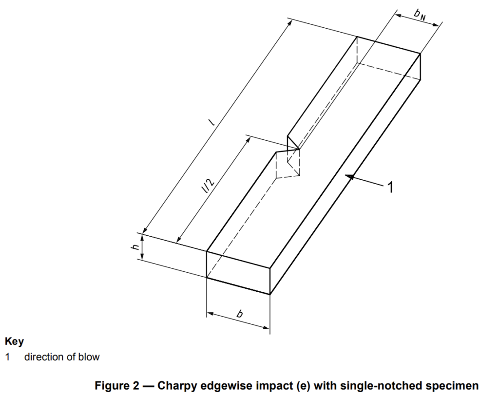
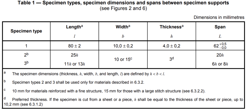
6.3.1.1.1 Type 1 test specimens, unnotched or with one of three different types of notch, shall be used as
specified in Tables 1 and 2 and shown in Figures 2 and 5. The notch shall be located at the centre of the
specimen. Type 1 specimens (see Table 1) may be taken from the central part of the type A multipurpose test specimen specified in ISO 3167.
6.3.1.1.2 The preferred type of notch is type A (see Table 2 and Figure 5). For most materials, unnotched
specimens or specimens with a single type A notch tested by edgewise impact (see 3.3) are suitable. If
specimens with a type A notch do not break during the test, specimens with a type C notch shall be used. If information on the notch sensitivity of the material is desired, specimens with notch types A, B and C shall be tested.
6.3.1.1.3 Unnotched or double-notched specimens tested by flatwise impact (see 3.4) can be used to study surface effects (see 1.3 and Annex A).
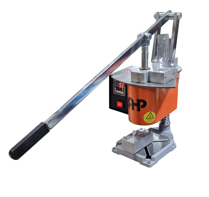
Summary of Equipment Needed to Do the Test
- Pendulum Impact Tester
- Manual Injection Molding Machine
- Notch Milling Machine
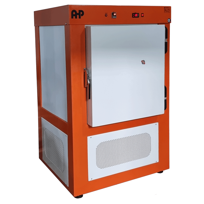
- Deep Freezer
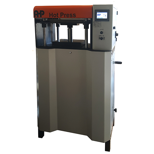
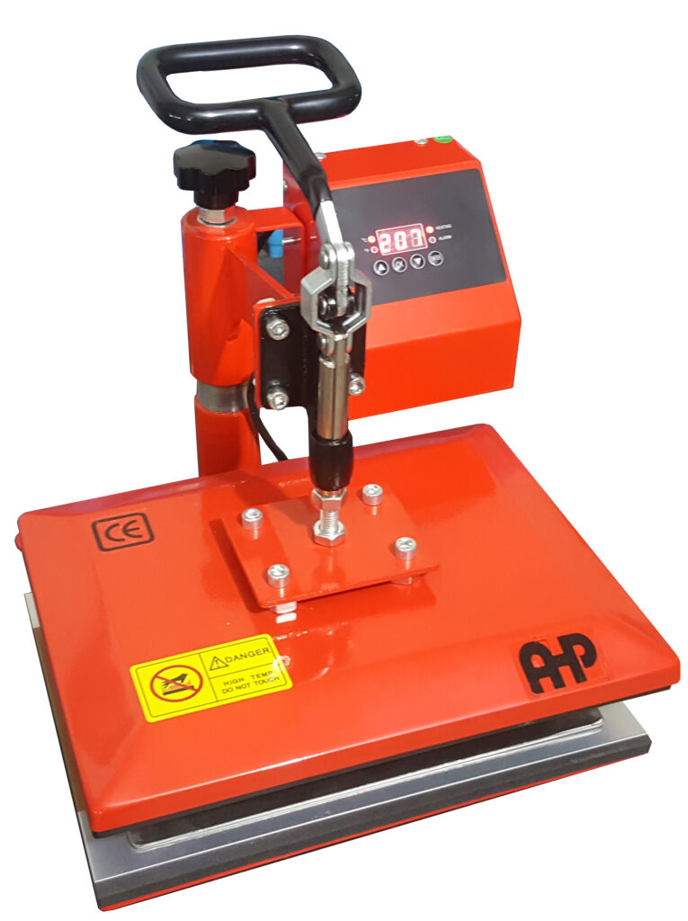
- Hot Press (Manual or Hydraulic)


