

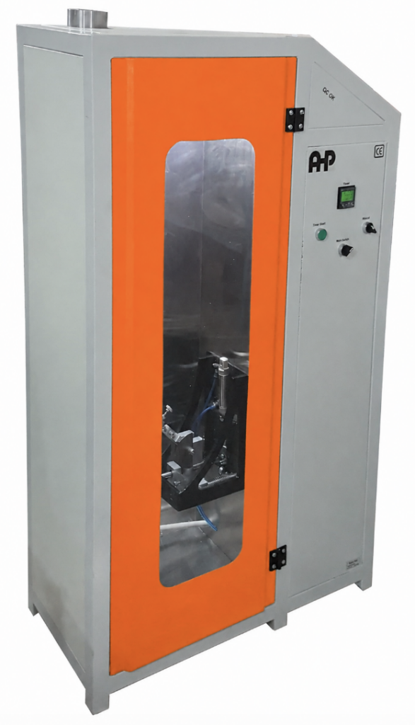
Complete Technical Guide to Resistance to Flame Propagation Testing of Non-Metallic and Composite Conduits
IEC 61386-1:2008 specifies general requirements for conduit systems used for cable management. Among its fire-hazard requirements, the standard establishes a specific test for determining whether non-metallic and composite conduits can be classified as non-flame propagating.
For conduits, compliance is evaluated by applying a standardized: 1 kW test flame
in accordance with: IEC 60695-11-2:2003
The conduit is mounted vertically inside a specified steel enclosure, exposed to the flame for a duration determined by its material thickness, and then evaluated according to defined extinction, dripping and charring criteria. This article covers only the requirements related to the flame propagation test contained in IEC 61386-1:2008.
1. Purpose of the Flame Propagation Test
The purpose of the test is to determine whether a conduit that may ignite when exposed to an external flame:
- limits flame propagation;
- extinguishes within a specified time after flame removal;
- does not ignite material beneath the specimen;
- and does not allow burning or charring to propagate excessively toward the upper end of the specimen.
A conduit classified as non-flame propagating may catch fire when an external flame is applied, but the flame shall not continue to propagate indefinitely and the conduit shall self-extinguish within the limits required by the standard.
2. Flame Propagation Classification
IEC 61386-1 classifies conduit systems according to resistance to flame propagation as:
Non-Flame Propagating
Classification: 1
Flame Propagating
Classification: 2
This characteristic forms the eleventh digit of the IEC 61386 conduit-system classification code.
3. Definition of a Non-Flame Propagating Conduit
A non-flame propagating conduit is a conduit that may catch fire as a result of an applied flame, but:
- the flame does not continue to propagate;
- and the conduit extinguishes itself within a limited time after removal of the external flame.
The test therefore evaluates controlled self-extinguishing behaviour, not complete immunity to ignition.
4. Products Subjected to the 1 kW Flame Test
The 1 kW flame test specified in Clause 13.1.3.2 applies to:
non-metallic conduits and composite conduits
that are intended to be classified as: non-flame propagating.
The conduit itself is tested using the 1 kW flame.
Conduit fittings are assessed separately under the standard using the glow-wire method and are therefore not part of the 1 kW flame procedure described here.
5. Standardized Flame Source
The flame used for the test shall be the:
1 kW Flame Specified in IEC 60695-11-2
IEC 61386-1 does not redefine the detailed burner construction, propane flow, air flow or flame calibration requirements.
Those requirements are taken from:
IEC 60695-11-2:2003 – Fire hazard testing – Test flames – 1 kW nominal pre-mixed flame
Therefore, a compliant IEC 61386-1 flame-propagation system requires a correctly established and confirmed IEC 60695-11-2 1 kW flame.
6. General Test Conditions
Unless otherwise specified, tests under IEC 61386-1 are performed at an ambient temperature of: 20 ± 5 °C
For non-metallic and composite conduit samples, general conditioning is required for at least: 240 h
at: 23 ± 2 °C
with relative humidity between: 40 % and 60 %
Testing is carried out immediately after this general conditioning.
Samples should be:
- clean;
- new;
- complete;
- representative of normal use.
7. Number of Samples
The flame propagation procedure is performed on: Three Samples
The standard explicitly requires that: all three samples shall pass.
Failure of one specimen means the flame-propagation requirement has not been satisfied under the normal acceptance rule.
8. Test Specimen Length
Each conduit specimen shall have a length of: 675 ± 10 mm
The specimen is mounted: vertically
inside the specified steel enclosure.
9. Test Enclosure
The test is performed inside a: rectangular metal enclosure with one open face
and in an area that is: substantially free from draughts.
The purpose of the enclosure is to provide a repeatable flame environment while limiting uncontrolled air movement around the specimen.
10. Steel Enclosure Dimensions
Figure 6 of IEC 61386-1 specifies the steel enclosure used for the flame propagation test.
The main dimensions shown are approximately:
Height 1300 ± 25 mm
Width 300 +25 / 0 mm
Depth 450 +25 / 0 mm
The enclosure has: one closed back face
and: one open front face
The specimen is mounted vertically inside the enclosure.
11. Specimen Position Inside the Enclosure
The specimen assembly is positioned:
vertically in the centre of the enclosure.
The general arrangement is defined in Figure 7.
The conduit is maintained in a straight vertical position by:
- two metal clamps;
- an internal steel rod.
12. Metal Clamps
Two metal clamps are used to support the specimen.
Each clamp is approximately: 25 mm wide
The distance between the clamps is: 550 ± 10 mm
The clamps should be positioned approximately: equidistant from the ends of the specimen.
13. Lower Clamp Height
The upper extremity of the lower clamp is positioned: 500 ± 10 mm
above the internal lower surface of the enclosure.
This dimension establishes the vertical reference for:
- specimen positioning;
- flame application point;
- burner geometry.
14. Internal Steel Support Rod
A steel rod is passed through the conduit specimen.
Its purpose is to keep the specimen:
- straight;
- vertical;
- stable during flame exposure.
The rod is: rigidly and independently mounted
and clamped at its upper end.
15. Steel Rod Diameter – Conduit Sizes up to 12 mm
For conduit sizes up to: 12 mm
the required steel rod diameter is: 2.0 ± 0.1 mm
16. Steel Rod Diameter – 16 mm to 25 mm Conduits
For conduit sizes from: 16 mm to 25 mm
the steel rod diameter is: 6.0 ± 0.1 mm
17. Steel Rod Diameter – 32 mm and Larger Conduits
For conduit diameters: 32 mm and above
the required steel rod diameter is: 16.0 ± 0.1 mm
18. Requirement for the Support Arrangement
The support system must not interfere with falling molten or burning material. The mounting arrangement shall therefore be designed so that:
drops from the specimen can fall freely onto the tissue paper below.
This is important because ignition of the tissue paper forms part of the acceptance criteria.
19. Pinewood Board
A suitable piece of: white pinewood board
is positioned on the lower surface of the test enclosure.
The approximate board thickness is: 10 mm
20. Tissue Paper
The pinewood board is covered with: one single layer of white tissue paper
The tissue paper serves as an indicator of whether:
- flaming droplets;
- molten particles;
- burning fragments
from the conduit can ignite material beneath the specimen. Ignition of this tissue paper constitutes a failure.
21. Burner Orientation
The burner is mounted so that its axis is inclined at: 45 ± 2°
to the vertical. This angle is a controlled part of the test geometry.
The burner shall remain in this position during flame application.
22. Burner-to-Specimen Distance
The distance from: the top of the burner tube
to: the conduit specimen
measured along the axis of the flame shall be: 100 ± 10 mm
This dimension is measured along the burner/flame axis, not horizontally or vertically.
23. Flame Application Point
The burner is positioned so that its flame axis intersects the surface of the conduit at a point: 100 ± 5 mm
above: the upper extremity of the lower clamp.
This establishes a precise and reproducible flame-application location.
24. Alignment of Flame and Conduit
The flame axis shall be arranged so that it: interacts with the axis of the specimen
as defined by the test arrangement.
The specimen is centrally located in the horizontal plane of the enclosure.
Correct alignment is critical because lateral displacement can alter:
- heat exposure;
- ignition behaviour;
- flame spread;
- charring distance.
25. Burner Position During the Test
Once the burner is correctly positioned: the flame shall not be moved during application.
The only permitted movement is: removing the burner at the end of the specified exposure period.
Therefore, unlike some flame tests where the operator follows a deforming specimen, this procedure requires a fixed flame position during exposure.
26. Flame Application Time Is Not Constant
One of the most important features of the IEC 61386-1 flame propagation test is that the flame exposure time is: dependent on conduit material thickness.
Thicker conduits receive a longer flame application time.
The exposure duration is selected from Table 9.
27. Determination of Material Thickness
Before selecting the flame application time, the material thickness of each sample must be determined.
IEC 61386-1 provides different measurement methods for:
- plain conduit;
- corrugated conduit;
- combined plain and corrugated conduit;
- combined plain, corrugated and plain conduit.
The procedures are specified in:
Normative Annex B.
28. Measurement of All Three Specimens
The material thickness is measured on: all three test samples.
For each specimen:
- the appropriate Annex B measurement method is used;
- the mean material thickness is calculated.
The three specimen mean values are then compared.
29. Thickness Used to Select Exposure Time
The standard requires use of: the highest mean material thickness
among the three test specimens. That value is used to determine the flame exposure time from Table 9.
This means that three different flame times are not normally selected for the three specimens.
Instead:
measure all three → calculate each mean → select the highest mean → use that value to establish the exposure time.
30. Complete Flame Application Time Table
| Mean Material Thickness | Flame Application Time |
|---|---|
| ≤0.5 mm | 15 s |
| >0.5 to 1.0 mm | 20 s |
| >1.0 to 1.5 mm | 25 s |
| >1.5 to 2.0 mm | 35 s |
| >2.0 to 2.5 mm | 45 s |
| >2.5 to 3.0 mm | 55 s |
| >3.0 to 3.5 mm | 65 s |
| >3.5 to 4.0 mm | 75 s |
| >4.0 to 4.5 mm | 85 s |
| >4.5 to 5.0 mm | 130 s |
| >5.0 to 5.5 mm | 200 s |
| >5.5 to 6.0 mm | 300 s |
| >6.0 mm | 500 s |
The specified flame application times have a positive tolerance as indicated in Table 9 of the standard.
31. Plain Conduit Thickness Measurement
For a plain conduit, thickness measurements are taken at: four locations
approximately equally spaced around: 360°
of the conduit circumference. If the four measured values are:
a₁, a₂, a₃, a₄
the mean material thickness is:
Mean Thickness = (a₁ + a₂ + a₃ + a₄) / 4
32. Corrugated Conduit Thickness Measurement
For a corrugated conduit, measurements are taken at both:
- the crest of the corrugation;
- the root of the corrugation.
Measurements are taken at four approximately equally spaced positions around the circumference.
This produces:
- four crest measurements;
- four root measurements.
The mean material thickness is calculated from the eight resulting thickness values as defined in Annex B.
33. Combined Plain and Corrugated Conduit
For conduit incorporating both:
- plain sections;
- corrugated sections;
measurements are made at:
- corrugation crest;
- corrugation root;
- plain section;
at four approximately equally spaced positions around 360°. The calculation method defined in Annex B accounts for both the corrugated and plain portions of the wall.
34. Combined Plain–Corrugated–Plain Construction
For conduit incorporating:
plain section → corrugated section → plain section
Annex B specifies measurement of:
- root;
- crest;
- both plain-wall sections
at four positions approximately equally spaced around the conduit circumference. The appropriate mean material thickness formula shall be used before selecting the flame exposure duration.
35. Complete Test Setup Sequence
A practical sequence based directly on IEC 61386-1 is:
Step 1 – Select Samples
Prepare: three new conduit samples representative of the product.
Step 2 – Condition the Samples
For non-metallic and composite conduits: at least 240 h
at: 23 ±2 °C
and: 40–60 % RH
Step 3 – Determine Material Thickness
Use Annex B according to conduit geometry.
Step 4 – Calculate the Mean Thickness of Each Sample
Calculate one mean value for each of the three samples.
Step 5 – Select Highest Mean Thickness
Use the highest of the three mean values.
Step 6 – Determine Flame Application Time
Select the corresponding duration from Table 9.
Step 7 – Prepare the Enclosure
Install the steel enclosure in a substantially draught-free area.
Step 8 – Install the Pine Board and Tissue Paper
Place the approximately 10 mm white pine board on the bottom of the enclosure.
Cover it with one layer of white tissue paper.
Step 9 – Install the Steel Rod
Select the correct rod diameter according to conduit size.
Step 10 – Mount the Conduit
Install the: 675 ±10 mm
sample vertically.
Step 11 – Install the Two Clamps
Use approximately: 25 mm wide
clamps spaced: 550 ±10 mm
apart.
Step 12 – Establish Lower Clamp Height
Set the upper edge of the lower clamp: 500 ±10 mm
above the enclosure floor.
Step 13 – Set Burner Angle
Adjust burner axis to: 45 ±2° from vertical
Step 14 – Set Burner Distance
Set burner tube-to-specimen distance along the flame axis to: 100 ±10 mm
Step 15 – Set Flame Impact Point
Align the flame to intersect the specimen:
100 ±5 mm above the upper end of the lower clamp
Step 16 – Apply the 1 kW Flame
Apply the IEC 60695-11-2 flame for the duration obtained from Table 9.
Step 17 – Keep Burner Stationary
Do not move the flame during exposure.
Step 18 – Remove the Flame
Remove the burner immediately at the end of the specified exposure period.
Step 19 – Observe Post-Flame Behaviour
Observe:
- continued flaming;
- sustained glowing;
- falling burning particles;
- tissue-paper ignition;
- propagation of burning/charring.
Step 20 – Allow Burning to Cease
Wait until any burning of the specimen has stopped.
Step 21 – Clean the Specimen
Wipe the specimen surface with: a cloth soaked with water
before evaluating the final char/burn limit.
36. Pass Criterion – No Ignition
The specimen passes if: it does not ignite.
In this case, no further ignition-related acceptance criteria need to be invoked for that sample.
37. Pass Criterion When Ignition Occurs
Ignition itself does not automatically constitute failure. A specimen that ignites can still pass if:
all required post-ignition criteria are satisfied.
38. Maximum Flaming / Glowing Duration
After removal of the test flame: flaming or glowing shall extinguish within 30 seconds.
Therefore: Post-Flame Burning/Glowing ≤30 s
is required.
52. Tissue Paper Acceptance Requirement
The white tissue paper underneath the specimen shall: not ignite.
Ignition caused by:
- flaming drops;
- glowing debris;
- molten polymer;
- burning fragments
therefore constitutes failure.
53. Upper Char / Burn Limit
After all flaming and glowing have extinguished:
there shall be: no evidence of burning or charring within 50 mm of the lower extremity of the upper clamp.
This requirement limits upward flame propagation along the conduit.
54. Why the 50 mm Criterion Is Important
The purpose of the upper limit is not merely to determine whether the specimen eventually self-extinguishes. A conduit could theoretically extinguish but still allow the combustion zone to travel a substantial distance upward.
IEC 61386-1 therefore places an additional boundary on: how far burning or charring may approach the upper clamp.
The region within: 50 mm below the lower end of the upper clamp
must remain free from evidence of burning or charring after extinction.
55. Final Acceptance Conditions
Each specimen passes if:
Either:
The specimen does not ignite
Or, if ignition occurs, all of the following are satisfied:
- Flaming/glowing extinguishes within 30 s after flame removal.
- The tissue paper underneath the specimen does not ignite.
- After extinction, there is no evidence of burning or charring within 50 mm of the lower end of the upper clamp.
56. Three-Sample Acceptance Rule
The standard requires: All Three Samples Shall Pass
Therefore:
Sample 1 = PASS
Sample 2 = PASS
Sample 3 = PASS
is required for compliance. The result is not determined by:
- averaging;
- majority vote;
- two out of three specimens.
57. Post-Test Cleaning
After completion of the test and after all burning has ceased: the specimen surface is cleaned by rubbing it with: a piece of cloth soaked with water.
This cleaning step is performed before the final visual assessment of burning/charring extent.
58. Test Enclosure – Technical Summary
The flame test enclosure includes:
- rectangular steel construction;
- open front;
- closed rear face;
- approximate height: 1300 ±25 mm;
- width: 300 +25/0 mm;
- depth: 450 +25/0 mm;
- vertically mounted conduit specimen;
- lower white pinewood board;
- white tissue paper;
- inclined burner.
The enclosure drawing is given in Figure 6 and the complete test arrangement in Figure 7.
59. Complete Test Geometry – Quick Reference
| Parameter | Requirement |
|---|---|
| Specimen length | 675 ±10 mm |
| Specimen orientation | Vertical |
| Clamp width | Approx. 25 mm |
| Clamp spacing | 550 ±10 mm |
| Lower-clamp upper edge above enclosure floor | 500 ±10 mm |
| Burner angle | 45 ±2° from vertical |
| Burner tube to specimen distance | 100 ±10 mm |
| Flame intersection point above lower clamp | 100 ±5 mm |
| Pinewood board thickness | Approx. 10 mm |
| Tissue paper | One layer, white |
| Flame source | IEC 60695-11-2, 1 kW |
| Number of specimens | 3 |
60. Steel Rod Selection – Quick Reference
| Conduit Size | Steel Rod Diameter |
|---|---|
| Up to 12 mm | 2.0 ±0.1 mm |
| 16–25 mm | 6.0 ±0.1 mm |
| 32 mm and above | 16.0 ±0.1 mm |
The rod must be independently secured and must maintain the conduit straight without obstructing falling debris.
61. Critical Variables Affecting Test Repeatability
The most important controlled parameters include:
- conformity of the 1 kW test flame;
- specimen conditioning;
- specimen length;
- material thickness determination;
- selected exposure time;
- specimen verticality;
- burner angle;
- burner-to-specimen distance;
- flame impact point;
- clamp spacing;
- steel-rod selection;
- draught conditions;
- tissue-paper position.
Small deviations in these variables can affect the apparent flame propagation behaviour.
62. Importance of Material Thickness
IEC 61386-1 intentionally changes flame exposure duration according to wall thickness.
The principle is:
Thin wall → shorter flame application
Thick wall → longer flame application
For example:
- ≤0.5 mm → 15 s
- 2.0–2.5 mm → 45 s
- 4.5–5.0 mm → 130 s
- 6.0 mm → 500 s
This prevents the same fixed exposure time from being applied indiscriminately to conduit constructions with very different thermal mass.
63. Example of Exposure-Time Selection
Assume three conduit specimens have calculated mean material thicknesses of:
- Sample 1: 2.18 mm
- Sample 2: 2.24 mm
- Sample 3: 2.31 mm
The highest mean thickness is: 2.31 mm
According to Table 9, the relevant thickness range is: over 2.0 mm up to 2.5 mm
Therefore, the flame application time for the test set is: 45 s
This example illustrates application of the standard’s selection logic.
64. Difference Between Flame Resistance and Fire Resistance
IEC 61386-1 distinguishes: reaction to fire / resistance to flame propagation
from: resistance to fire.
The 1 kW test described here assesses:
flame propagation behaviour.
It does not demonstrate that the conduit can maintain electrical circuit integrity during a fire. The general standard states that resistance-to-fire requirements are not applicable here, with fire-resistant conduits for survival circuits requiring separate consideration.
65. Difference Between Conduit and Conduit-Fitting Fire Tests
Within IEC 61386-1:
Conduit
Non-metallic and composite conduits are evaluated using: 1 kW flame according to IEC 60695-11-2
Conduit Fitting
Non-metallic and composite conduit fittings are evaluated using: 750 °C glow-wire according to IEC 60695-2-11
These two methods should not be confused when defining the capabilities of a test machine.
66. Flame Propagation Classification Code
In Annex A, resistance to flame propagation appears as the: Eleventh Digit
of the conduit-system classification code.
The values are:
1 = Non-flame propagating
2 = Flame propagating
This classification can form part of the product’s declared technical characteristics.
67. Marking Related to Flame Propagation
IEC 61386-1 also contains colour-related requirements relevant to flame-propagation classification.
Flame-propagating material shall be: orange
and shall not obtain the orange colour merely through superficial painting or a similar surface process.
A non-flame-propagating material may generally be another colour, subject to the marking provisions defined by the standard.
This is a product-identification requirement rather than part of the flame-test procedure itself.
68. Pre-Test Checklist
Before starting the test, verify:
✓ Product is a non-metallic or composite conduit
✓ Three appropriate test specimens available
✓ Samples conditioned for at least 240 h
✓ Conditioning temperature = 23 ±2 °C
✓ Conditioning RH = 40–60 %
✓ Specimens clean and new
✓ Mean material thickness measured correctly
✓ Highest mean thickness identified
✓ Correct Table 9 exposure time selected
✓ IEC 60695-11-2 1 kW flame available
✓ Steel enclosure installed
✓ Test area substantially free from draughts
✓ White pinewood board installed
✓ Single layer of white tissue paper installed
✓ Correct steel rod selected
✓ Correct clamps installed
✓ Specimen vertical and straight
69. Geometry Checklist
Before ignition verify:
✓ Specimen length = 675 ±10 mm
✓ Clamp spacing = 550 ±10 mm
✓ Clamp width ≈ 25 mm
✓ Lower clamp reference height = 500 ±10 mm
✓ Burner angle = 45 ±2°
✓ Burner-to-specimen distance = 100 ±10 mm
✓ Flame application point = 100 ±5 mm above lower clamp
✓ Flame axis correctly aligned with specimen
✓ Falling debris path to tissue paper unobstructed
70. Test Execution Checklist
During the test:
✓ Apply standardized 1 kW flame
✓ Start exposure timer at correct point
✓ Apply flame for Table 9 duration
✓ Do not move burner during exposure
✓ Remove burner at end of required time
✓ Observe continuing flames
✓ Observe sustained glowing
✓ Observe falling particles
✓ Observe tissue paper
✓ Record extinction behaviour
71. Acceptance Checklist
For every specimen verify:
✓ Specimen did not ignite
OR, if ignition occurred:
✓ Flame/glow extinguished within 30 s
✓ Tissue paper did not ignite
✓ No burning/charring within 50 mm of lower end of upper clamp
Final result:
✓ Sample 1 PASS
✓ Sample 2 PASS
✓ Sample 3 PASS
Only then can the test set satisfy the flame-propagation requirement.
72. Recommended Test Report Data
A detailed flame-propagation test report should record:
- standard: IEC 61386-1:2008;
- flame-source standard: IEC 60695-11-2:2003;
- product identification;
- conduit type;
- nominal conduit size;
- plain/corrugated/combined construction;
- specimen identification;
- conditioning duration;
- conditioning temperature;
- conditioning humidity;
- individual wall-thickness measurements;
- calculated mean thickness of each specimen;
- highest mean thickness;
- selected flame application time;
- steel rod diameter;
- specimen length;
- clamp spacing;
- burner angle;
- burner distance;
- flame application point;
- ignition occurrence;
- duration of post-flame flaming/glowing;
- tissue-paper ignition;
- burning/charring extent;
- result for each specimen;
- overall PASS/FAIL result.
75. Complete Test Logic
The complete procedure can be summarized as:
Condition three specimens
↓
Measure material thickness
↓
Calculate mean thickness for each specimen
↓
Select highest mean thickness
↓
Determine exposure time from Table 9
↓
Mount 675 ±10 mm conduit vertically
↓
Install correct internal steel rod
↓
Set clamps 550 ±10 mm apart
↓
Position lower clamp at 500 ±10 mm
↓
Position burner at 45 ±2°
↓
Set burner distance to 100 ±10 mm
↓
Set impact point 100 ±5 mm above lower clamp
↓
Apply IEC 60695-11-2 1 kW flame
↓
Maintain flame for specified exposure time
↓
Remove flame
↓
Observe extinction and falling material
↓
Verify extinction within 30 s
↓
Verify tissue paper does not ignite
↓
Verify no burn/char within 50 mm of upper clamp
↓
Repeat for all three specimens
↓
All three must pass