

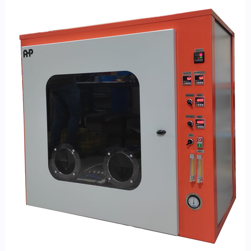
IEC 60695-11-2:2003 specifies the detailed requirements for producing a standardized 1 kW nominal pre-mixed propane test flame for fire-hazard testing.
The standard applies to:
- electrotechnical equipment;
- subassemblies;
- components;
- solid electrical insulating materials;
- other combustible materials.
A flame cannot be considered standardized only because its nominal thermal power is approximately 1 kW. The complete burner, fuel supply, air supply, flame geometry, measurement system and thermal confirmation procedure must comply with the specified requirements.
1. Scope of the Standard
IEC 60695-11-2 defines the production of a standardized: 1 kW nominal propane-based pre-mixed test flame
for use in fire-hazard testing. The standard is intended to provide a repeatable laboratory ignition source where actual fire conditions cannot be reproduced exactly.
The standardized flame must satisfy the requirements defined for:
- burner construction;
- propane quality;
- propane flow;
- combustion-air flow;
- flow measurement;
- pressure measurement;
- flame dimensions;
- chamber conditions;
- copper-block confirmation;
- temperature and time measurement.
2. Definition of a Standardized 1 kW Test Flame
A standardized 1 kW nominal test flame is a flame that conforms to IEC 60695-11-2 and satisfies all requirements specified in the relevant clauses of the standard.
The standardized flame is therefore defined by both:
Physical flame characteristics
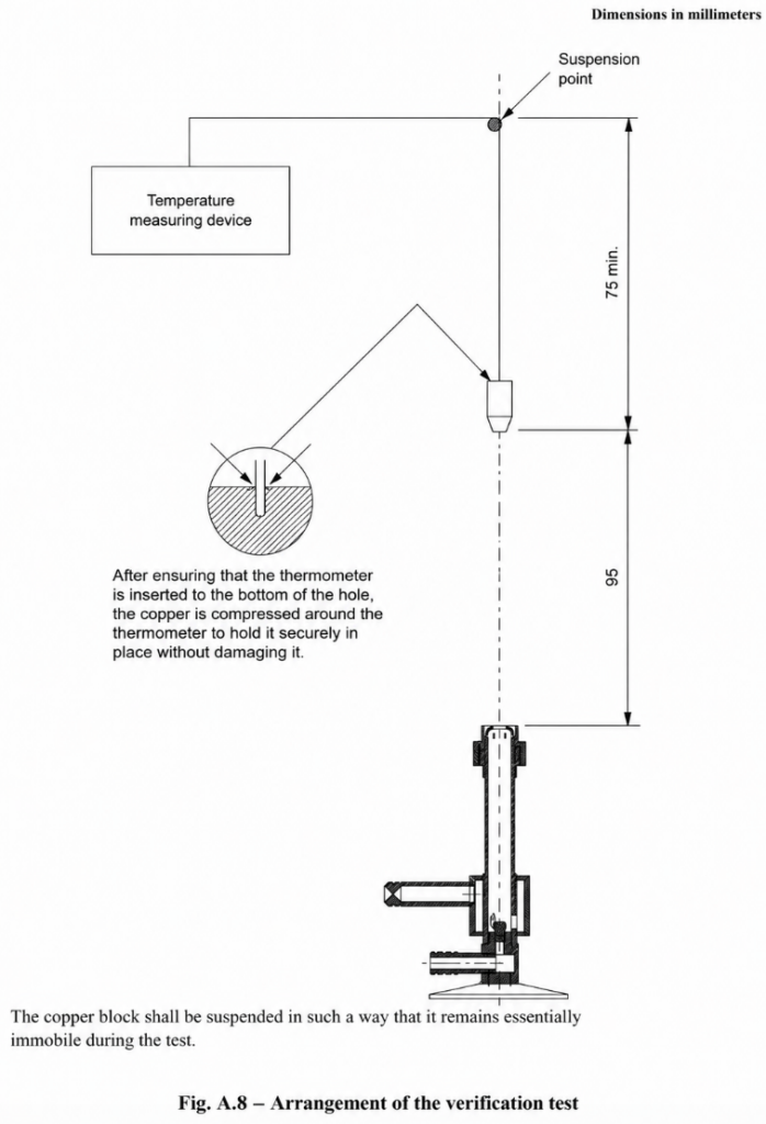
and
Thermal performance
The thermal performance is confirmed using a standardized copper block.
3. Burner and Supply Arrangement
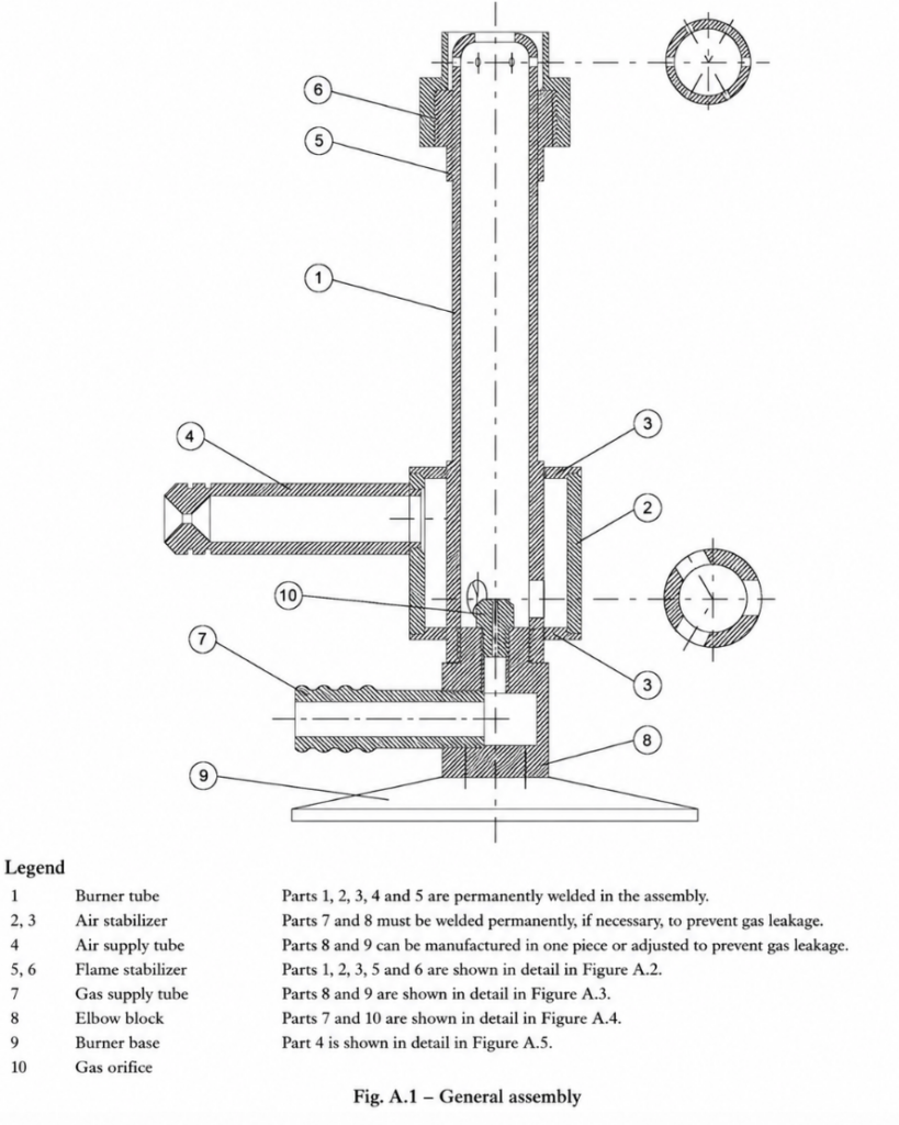
The burner system includes:
- burner tube;
- air collectors;
- air supply tube;
- flame stabilizer;
- gas supply tube;
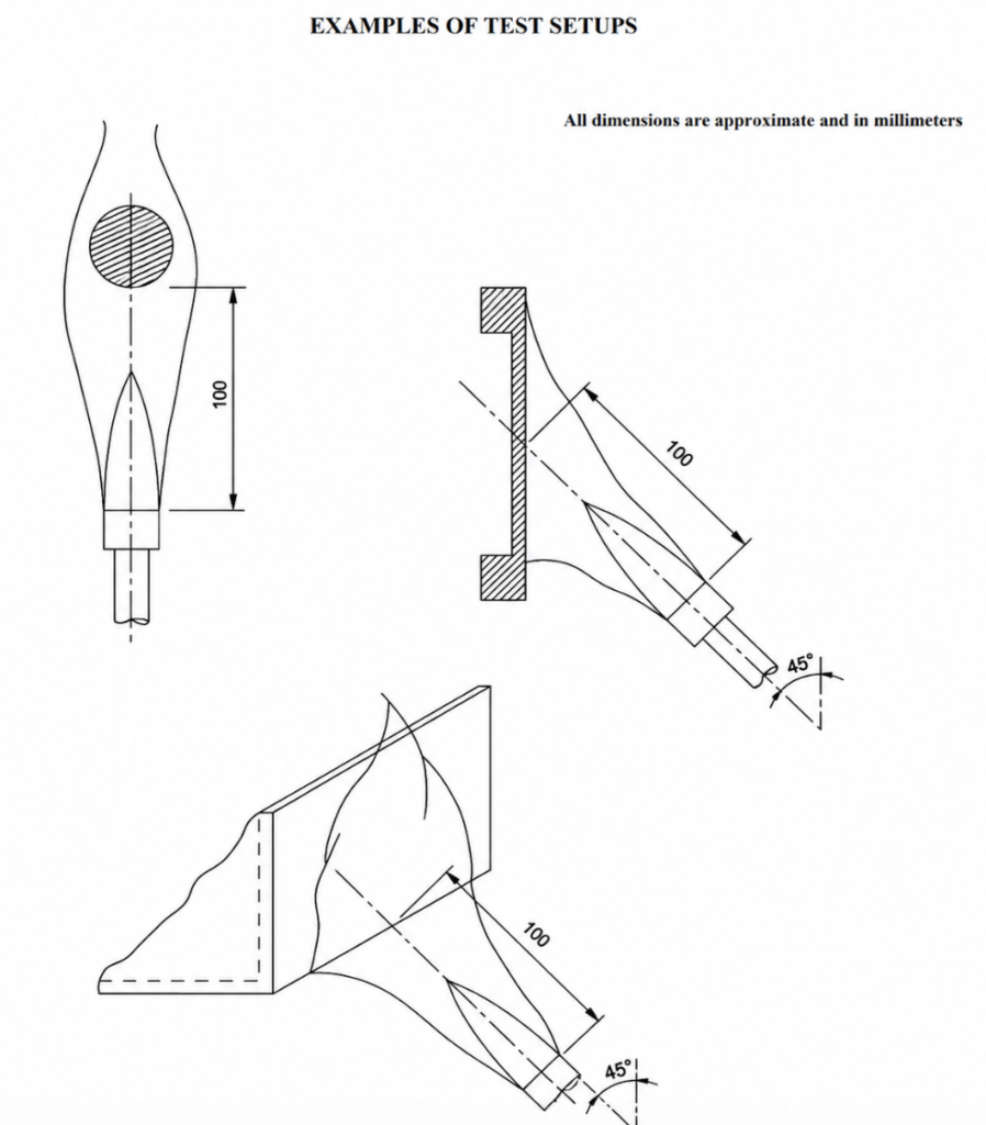
- elbow block;
- burner base;
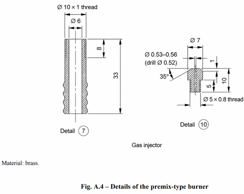
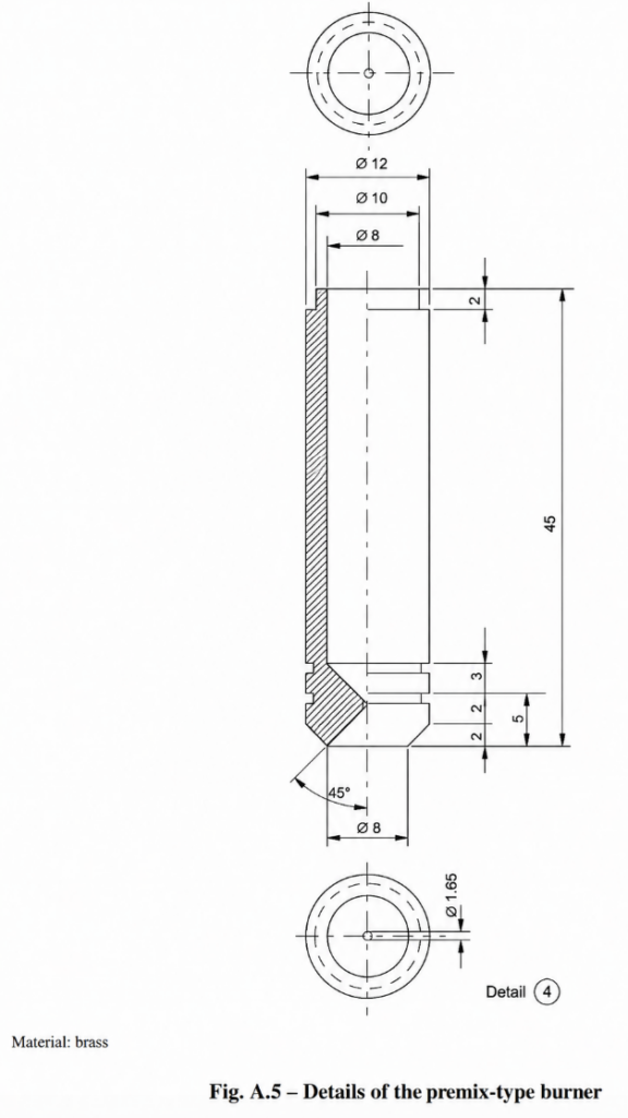
- gas injector.
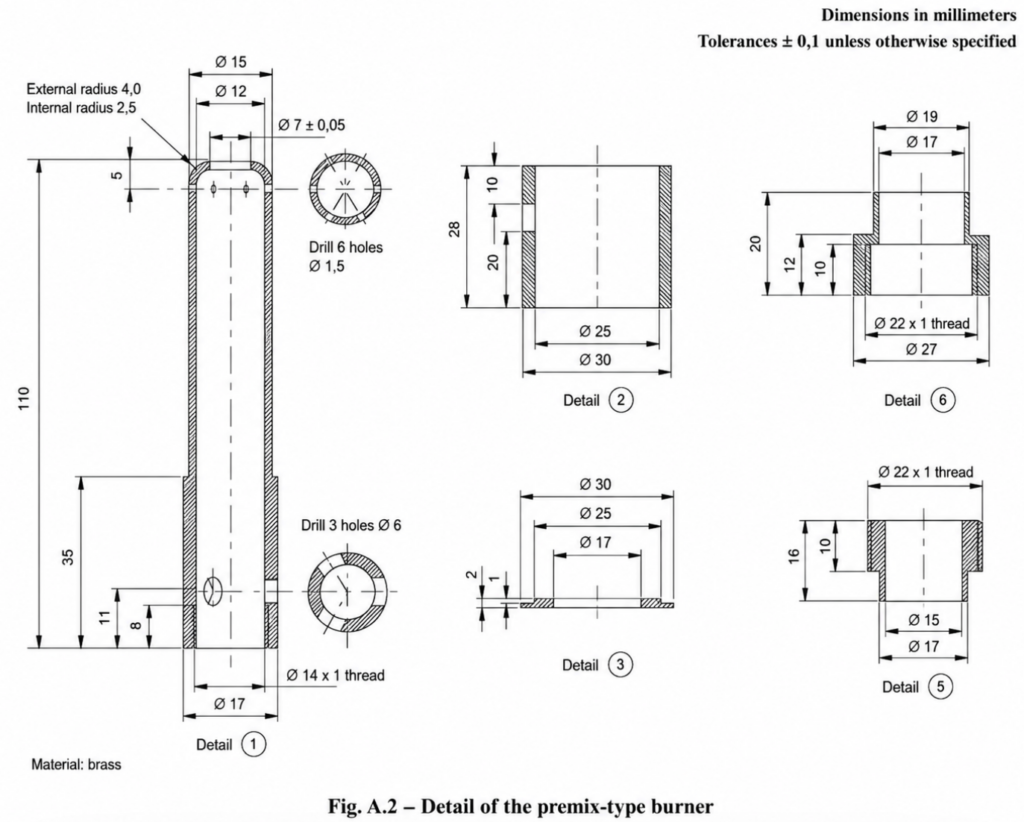
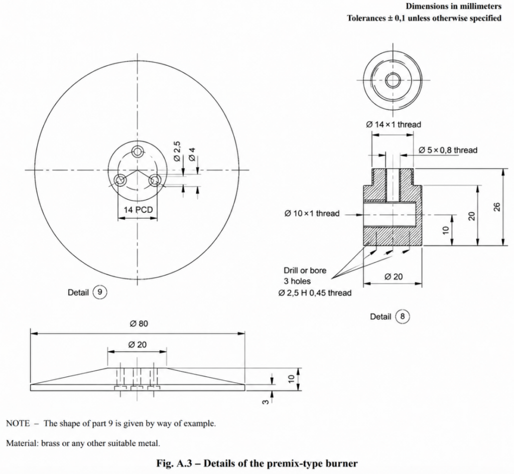
The burner construction shall follow the detailed drawings provided in Annex A of the standard.
4. Fuel Gas Requirement
The required fuel is: Propane
with a minimum purity of: 98 %
The propane flow shall be equivalent to: 650 ml/min ± 30 ml/min
at: 23 °C and: 0.1 MPa
Measurements made under actual laboratory conditions shall be corrected to the specified reference conditions.
5. Combustion Air Requirement
The burner shall be supplied with air at a flow rate equivalent to: 10 L/min ± 0.5 L/min
at: 23 °C and: 0.1 MPa
The air shall be essentially free from:
- oil;
- water
The standard also requires measurement capability for ambient:
- temperature;
- pressure.
These measurements are necessary when flow correction is required.
6. Flowmeter Requirements
Two separate flowmeters are required.
Propane Flowmeter Suitable for measuring: 650 ml/min with a tolerance of: ±2 %
Air Flowmeter Suitable for measuring: 10 L/min with a tolerance of: ±2 %
Mass flowmeters are identified as the preferred means of accurately controlling fuel and air flow.
Alternative flow-measurement methods may be used if equivalent accuracy can be demonstrated.
7. Manometer Requirements
Two manometers are required for the conventional supply arrangement.
The required measurement range is: 0 MPa to 0.1 MPa
Water manometers may be used. When mass flowmeters are used: manometers are not required.
8. Control Valves
Two control valves are required: Gas Control Valve
Used to establish the propane flow. Air Control Valve
Used to establish the combustion-air flow.
Both flows shall remain within the specified tolerances.
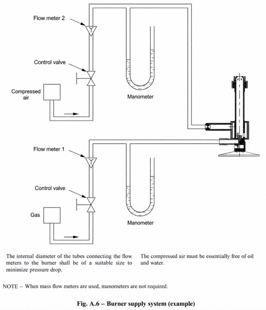
9. Burner Supply Configuration
The typical supply arrangement consists of two independent circuits.
Air Circuit
Compressed air source
→ Control valve
→ Air flowmeter
→ Manometer
→ Burner
Gas Circuit
Propane source
→ Control valve
→ Gas flowmeter
→ Manometer
→ Burner
The internal diameter of the connecting tubes shall be sufficient to minimize pressure loss.
10. Burner Assembly Components
The burner assembly consists of the following principal components:
- Burner tube
- Air collector
- Air collector
- Air supply tube
- Flame stabilizer
- Flame stabilizer
- Gas supply tube
- Elbow block
- Burner base
- Gas injector
The component geometry shall follow the detailed Annex A drawings.
11. Burner Assembly Construction
The standard specifies assembly details intended to prevent leakage and maintain mechanical integrity.
Parts 1, 2, 3, 4 and 5 are permanently joined during assembly.
Parts 7 and 8 may be permanently joined if necessary to prevent gas leakage.
Parts 8 and 9 may either:
- be fabricated in one piece;
- or be joined in a way that prevents gas leakage.
12. Burner Material
The burner is manufactured primarily from: Brass
or another suitable metal where permitted.
Unless otherwise specified in the detailed drawings:
Linear tolerance ±0.1 mm
Angular tolerance ±30 minutes
13. Burner Tube Geometry
The detailed burner drawing includes a principal tube length of approximately: 110 mm
The burner geometry includes:
- an upper outside diameter of approximately 15 mm;
- an internal passage defined by the standard drawing;
- air-inlet holes;
- threaded lower sections;
- the flame-stabilizer interface.
The burner should be manufactured according to the complete IEC drawing rather than by using only approximate commercial dimensions.
14. Gas Injector
The gas injector is one of the critical burner components.
The detailed drawing specifies a small propane orifice with a diameter in the approximate range of: 0.53 mm to 0.56 mm
The injector is removable for cleaning. Because the injector strongly affects gas velocity and mixing, dimensional accuracy and cleanliness are important for reproducible flame performance.
15. Flame Stabilizer
The burner includes a flame stabilizer.
The stabilizer helps maintain:
- a stable flame;
- a symmetrical flame;
- repeatable flame geometry.
The stabilizer is removable for cleaning.
16. Required Flame Geometry
The standardized flame shall appear: stable
and: symmetrical
The approximate flame dimensions are:
Blue Cone Height 50 mm to 60 mm
Overall Flame Height 170 mm to 190 mm
The flame is observed in the laboratory chamber under subdued lighting conditions.
17. Laboratory Test Chamber
The burner shall operate inside a suitable laboratory chamber.
Minimum internal volume: 1.0 m³
The chamber shall:
- provide a draught-free environment;
- allow normal thermal circulation around the specimen;
- permit observation of the test;
- have dark internal surfaces.
18. Chamber Illumination
A lux meter is positioned at the location of the test flame and directed toward the rear of the chamber.
The recorded illumination shall be: less than 20 lx
This provides appropriate visual conditions for flame observation.
19. Extraction System
An exhaust or extraction system may be installed to remove combustion products.
However: During the test
The extraction system shall be: OFF
Immediately after the test
The extraction system shall be: ON
The extraction airflow must not disturb the standardized flame during testing.
20. Oxygen Availability
The amount of oxygen available inside the chamber can affect combustion behaviour.
For tests involving long burning periods, the standard notes that a chamber volume of: 1.0 m³
may not always be sufficient for accurate results. This should be considered when evaluating chamber suitability.
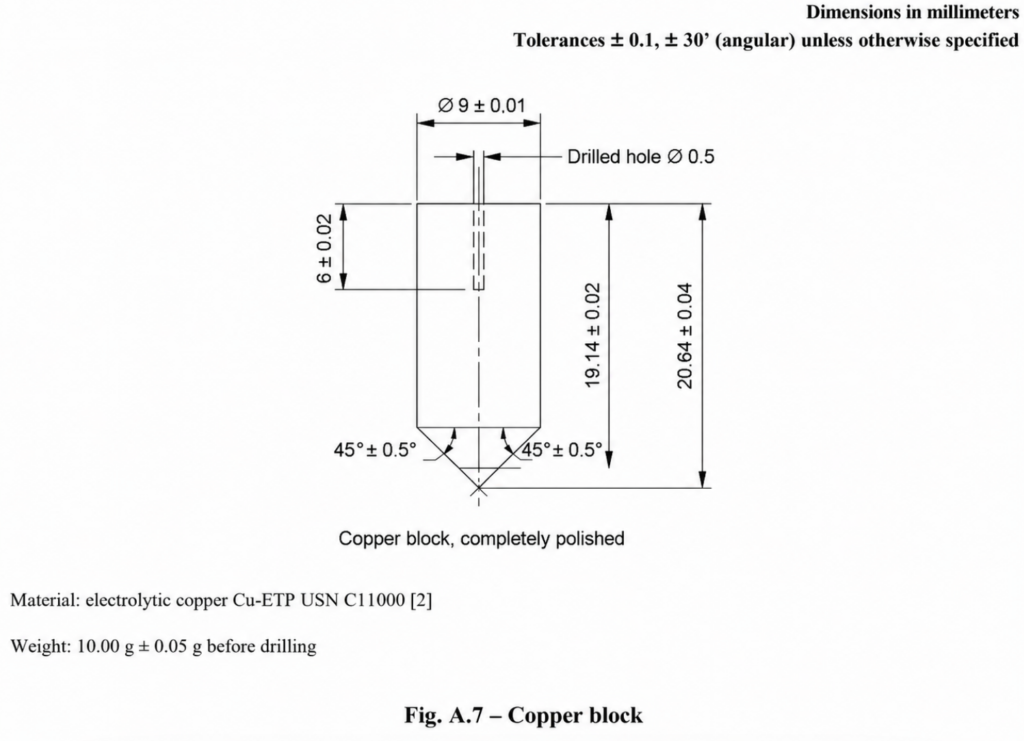
21. Copper Confirmation Block
The standardized flame is confirmed using a precision copper block.
Material
High-conductivity electrolytic copper: Cu-ETP UNS C11000
Diameter 9 mm
Mass 10.00 g ± 0.05 g
before drilling. The block is fully machined and polished.
22. Copper Block Dimensions
The detailed drawing specifies:
Diameter Ø9 ±0.01 mm
Thermocouple Hole Ø0.5 mm
Principal Dimensions
19.14 ±0.02 mm
20.64 ±0.04 mm
6 ±0.02 mm
Lower Angles
45° ±0.5°
Unless otherwise stated:
Linear tolerance ±0.1 mm
Angular tolerance ±30 minutes
23. Importance of Copper Block Accuracy
The copper block acts as the reference thermal load for flame confirmation.
Its:
- mass;
- geometry;
- material;
- surface condition;
- thermocouple position
directly affect the measured heating time. Therefore, the copper block should be treated as a calibrated reference component of the test system.
24. Thermocouple Requirements
The copper-block temperature is measured using a: Class 1 fine-wire thermocouple
with:
- mineral insulation;
- metal sheath;
- insulated junction.
The nominal overall diameter shall be: 0.5 mm
A suitable example is: Type K – NiCr/NiAl
The welded point is located inside the sheath.
25. Thermocouple Temperature Capability
The thermocouple sheath shall withstand continuous operation at: at least 1050 °C
A suitable nickel-based heat-resistant alloy can satisfy this requirement.
Thermocouple tolerances shall comply with: IEC 60584-2, Class 1
26. Thermocouple Installation
The thermocouple shall be inserted completely into the drilled copper-block hole.
The preferred method is then to compress the copper around the thermocouple to retain it securely. This provides the intended thermal contact between:
- thermocouple;
- copper block.
27. Temperature and Time Recording System
The temperature/time indicating or recording system shall be suitable for measuring the time required to heat the copper block from: 100 °C ±5 °C
to: 700 °C ±3 °C
The permitted tolerance of the measured time is: ±0.5 s
28. Principle of Flame Confirmation
The flame is thermally confirmed by measuring the heating response of the standardized copper block.
Required temperature increase: 100 ±5 °C → 700 ±3 °C
Required heating time: 45 ±5 s
This corresponds to an acceptable interval of: 40 s to 50 s
for the mean result.
29. Confirmation Test Arrangement
The copper block is suspended above the burner.
The suspension shall keep the block essentially stationary during the test.
The confirmation arrangement includes:
- burner;
- copper block;
- thermocouple;
- temperature measurement system;
- suspension point.
The detailed arrangement is defined in Figure A.8.
30. Confirmation Geometry
The detailed confirmation drawing includes an approximate vertical distance of: 95 mm
between the burner reference position and the copper block.
The suspension arrangement also shows: 75 mm minimum
above the block. The exact arrangement should follow the standard drawing.
31. Complete Flame Confirmation Procedure
Step 1 – Prepare the Apparatus
Install the burner, fuel system, air system, copper block and measurement system. Ensure all gas and air connections are leak-free.
Step 2 – Move the Burner Away
Temporarily move the burner away from the copper block. This prevents preheating during preliminary adjustment.
Step 3 – Ignite the Burner
Ignite the propane/air mixture.
Step 4 – Set the Propane Flow
Adjust to: 650 ±30 ml/min
Step 5 – Set the Air Flow
Adjust to: 10 ±0.5 L/min
Step 6 – Verify Flame Geometry
Check:
Blue cone = 50–60 mm
Overall flame = 170–190 mm
Step 7 – Check Flame Stability
Confirm that the flame is:
- stable;
- symmetrical.
Step 8 – Stabilize the Burner
Allow the burner to operate for at least:
5 minutes
Step 9 – Recheck Flows
Verify that propane and air flow rates remain within tolerance.
Step 10 – Start Measurement
Activate the temperature and timing system.
Step 11 – Reposition the Burner
Move the burner beneath the copper block.
Step 12 – Measure Heating Time
Measure the time required for: 100 ±5 °C → 700 ±3 °C
32. Number of Confirmation Measurements
Perform: three determinations
of the copper-block heating time. Between determinations, allow the block to cool naturally in air to: below 50 °C
before repeating the test.
33. New Copper Block Conditioning
If the copper block has not been used previously: perform one preliminary heating run. This run is used to condition the copper-block surface.
The result shall be: discarded
and not included in the final calculation.
34. Calculation of Final Confirmation Result
After three valid determinations:
calculate the: average heating time
in seconds.
The average result shall satisfy: 45 ±5 s
35. Example Confirmation Calculation
Example:
Test 1 = 44.0 s
Test 2 = 45.2 s
Test 3 = 46.1 s
Average: 45.1 s
This result is within the required: 40–50 s
range. This example is illustrative only.
36. Recommended Arrangement for Equipment Testing
When the flame is used for testing equipment, unless otherwise specified by the relevant product standard, the recommended distance from: the top of the burner tube
to: the surface of the test specimen
is approximately: 100 mm
The burner remains fixed in position during the test.
37. Why the 100 mm Distance Is Used
The 100 mm spacing provides better reproducibility than positioning the specimen directly at the tip of the blue cone. This reduces operator-dependent variation in flame application.
38. Material Strip Testing
For strip specimens, the operator may move the flame to follow:
- deformation;
- burning;
- movement of the specimen.
The tip of the blue cone should remain: as close as possible to the specimen without touching it.
39. Burner Tilt
The burner should be tilted where necessary so that falling debris does not enter the burner.
This prevents:
- contamination;
- blockage;
- flame instability;
- incorrect subsequent test results.
40. Apparatus Classification
An apparatus satisfying the requirements of IEC 60695-11-2 and producing the standardized 1 kW nominal test flame may be designated:
“1 kW nominal test flame apparatus, conforming to IEC 60695-11-2.”
41. Important Difference Between Flame Confirmation and Product Evaluation
IEC 60695-11-2 primarily standardizes: the 1 kW test flame
and: its confirmation method
It does not define a universal pass/fail criterion for every material or finished product.
The relevant product or material standard must define:
- specimen preparation;
- flame application duration;
- number of applications;
- test position;
- acceptance criteria;
- afterflame criteria;
- damage criteria;
- classification requirements.
42. Technical Specification Summary
| Parameter | Requirement |
|---|---|
| Standard | IEC 60695-11-2:2003 |
| Nominal flame power | 1 kW |
| Flame type | Pre-mixed |
| Fuel | Propane |
| Fuel purity | ≥98 % |
| Propane flow | 650 ±30 ml/min |
| Air flow | 10 ±0.5 L/min |
| Reference temperature | 23 °C |
| Reference pressure | 0.1 MPa |
| Flowmeter accuracy | ±2 % |
| Manometer range | 0–0.1 MPa |
| Blue cone height | 50–60 mm |
| Overall flame height | 170–190 mm |
| Copper block material | Cu-ETP UNS C11000 |
| Copper block diameter | 9 mm |
| Copper block mass | 10.00 ±0.05 g |
| Thermocouple | Class 1 |
| Thermocouple diameter | 0.5 mm |
| Confirmation range | 100 ±5 °C to 700 ±3 °C |
| Confirmation result | 45 ±5 s |
| Timing tolerance | ±0.5 s |
| Burner stabilization | ≥5 min |
| Number of measurements | 3 |
| Cooling between runs | <50 °C |
| Chamber volume | ≥1.0 m³ |
| Chamber illumination | <20 lx |
| Recommended equipment spacing | ≈100 mm |
43. Pre-Test Checklist
✓ Correct IEC burner installed
✓ Burner clean
✓ Gas injector clean
✓ Flame stabilizer clean
✓ Propane purity ≥98 %
✓ Propane flowmeter available
✓ Air flowmeter available
✓ Flowmeter accuracy ±2 %
✓ Air free from oil and water
✓ Gas and air connections leak-free
✓ Copper block correct material
✓ Copper block correct mass
✓ Thermocouple correctly installed
✓ Temperature measurement system operational
✓ Timing system operational
✓ Chamber volume ≥1.0 m³
✓ Chamber draught-free
✓ Chamber illumination <20 lx
✓ Extraction system OFF during test
44. Flame Adjustment Checklist
✓ Propane flow = 650 ±30 ml/min
✓ Air flow = 10 ±0.5 L/min
✓ Blue cone = 50–60 mm
✓ Overall flame = 170–190 mm
✓ Flame stable
✓ Flame symmetrical
✓ Burner stabilized for at least 5 minutes
45. Confirmation Checklist
✓ Copper block correctly suspended
✓ Thermocouple fully inserted
✓ Burner aligned correctly
✓ Temperature system active
✓ Start temperature = 100 ±5 °C
✓ End temperature = 700 ±3 °C
✓ Copper block cooled below 50 °C between runs
✓ Three valid measurements completed
✓ New-block conditioning run discarded
✓ Average result calculated
✓ Average result = 45 ±5 s
46. Engineering Significance
The IEC 60695-11-2 test flame is a controlled thermal source.
The engineering logic is:
Control the fuel
↓
Control the air
↓
Control the burner geometry
↓
Control the flame dimensions
↓
Stabilize the burner
↓
Measure thermal output
↓
Confirm using the copper block
↓
Use the confirmed flame for the applicable fire-hazard test
The standardized flame is therefore not simply a large propane flame. It is a reproducible laboratory ignition source whose thermal performance must be demonstrated before use.
1 kW Flame Tester According to IEC 60695-11-2 :2003
- Digital timer
- Rotameter type flow controller
- Gas pressure indicator
- Automatic flame application on sample piece
- Chamber size according to the standard
- Sample positioning 2 axes linear mechanism
- Copper block and measurement unit with WINDOWS software for verification of flame is as option (Not included in standard delivery)
- Standard: IEC 60695-11-2:2003
- Nominal flame power: 1 kW
- Flame type: Pre-mixed
- Fuel: Propane
- Fuel purity: ≥98%
- Propane flow rate: 650 ± 30 ml/min
- Air flow rate: 10 ± 0.5 L/min
- Reference temperature: 23 °C
- Reference pressure: 0.1 MPa
- Flowmeter accuracy: ±2%
- Manometer range: 0–0.1 MPa
- Blue cone height: 50–60 mm
- Overall flame height: 170–190 mm
- Copper block material: Cu-ETP UNS C11000
- Copper block diameter: 9 mm
- Copper block mass: 10.00 ± 0.05 g
- Thermocouple: Class 1
- Thermocouple diameter: 0.5 mm
- Confirmation temperature range: 100 ± 5 °C to 700 ± 3 °C
- Confirmation result: 45 ± 5 s
- Timing tolerance: ±0.5 s
- Burner stabilization time: ≥5 min
- Number of measurements: 3
- Cooling temperature between runs: <50 °C
- Chamber volume: ≥1.0 m³
- Chamber illumination: <20 lx
- Recommended equipment spacing: ≈100 mm