

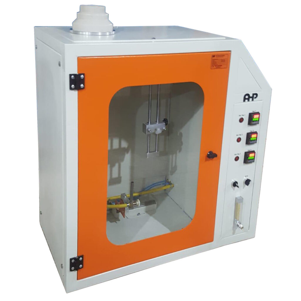
IEC 60695-11-3:2012 specifies the apparatus, operating conditions and confirmational test methods required to produce standardized 500 W nominal premixed test flames for fire-hazard testing.
Unlike IEC 60695-11-4, which specifies a 50 W flame, IEC 60695-11-3 addresses a substantially higher-energy 500 W flame, with an approximate overall flame height of 125 mm.
The standard defines two valid methods:
- Method A – 500 W premixed methane flame using adjustable, existing-type burner hardware
- Method C – 500 W premixed methane or propane flame using specially developed non-adjustable burner hardware
Methods B and D, which appeared in earlier technical specifications, have been withdrawn.
Both current methods are designed to produce a standardized flame with comparable thermal performance, which is verified by heating a specified copper block from 100 °C to 700 °C in 54 ± 2 seconds.
This article provides a detailed technical overview of:
- operating principle;
- Method A;
- Method C;
- burner construction;
- burner dimensions;
- fuel requirements;
- gas and air flow requirements;
- back-pressure requirements;
- flowmeters and manometers;
- copper calibration block;
- thermocouple;
- temperature and time measurement;
- laboratory chamber;
- flame geometry;
- flame-height gauge;
- flame production;
- calibration and confirmation;
- acceptance criteria;
- equipment test arrangements;
- material test arrangements;
- and the principal differences between Method A and Method C.
1. Scope of IEC 60695-11-3
IEC 60695-11-3 specifies detailed requirements for producing either of two standardized:
500 W nominal premixed test flames
The approximate overall height of either flame is: 125 mm
The two methods differ primarily in burner construction and control of the fuel/air mixture.
Method A
Method A uses: Methane only and is based on adjustable existing-type burner hardware.
Method C
Method C uses either: Methane or: Propane
and employs specially developed non-adjustable burner hardware with separately controlled fuel and air supplies. Despite the different methods of producing the flame, both methods use the same basic thermal confirmation principle.
2. Standardized 500 W Test Flame
A flame should not be considered a standardized IEC 60695-11-3 flame merely because:
- it visually appears similar;
- it has an approximately 125 mm height;
- or the burner is rated nominally at 500 W.
Compliance depends on the complete system.
The specified:
- burner geometry;
- fuel;
- fuel purity;
- fuel flow;
- air supply where applicable;
- pressure conditions;
- flame dimensions;
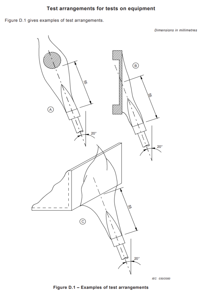
- chamber conditions;
- copper block;
- thermocouple;
- measurement system;
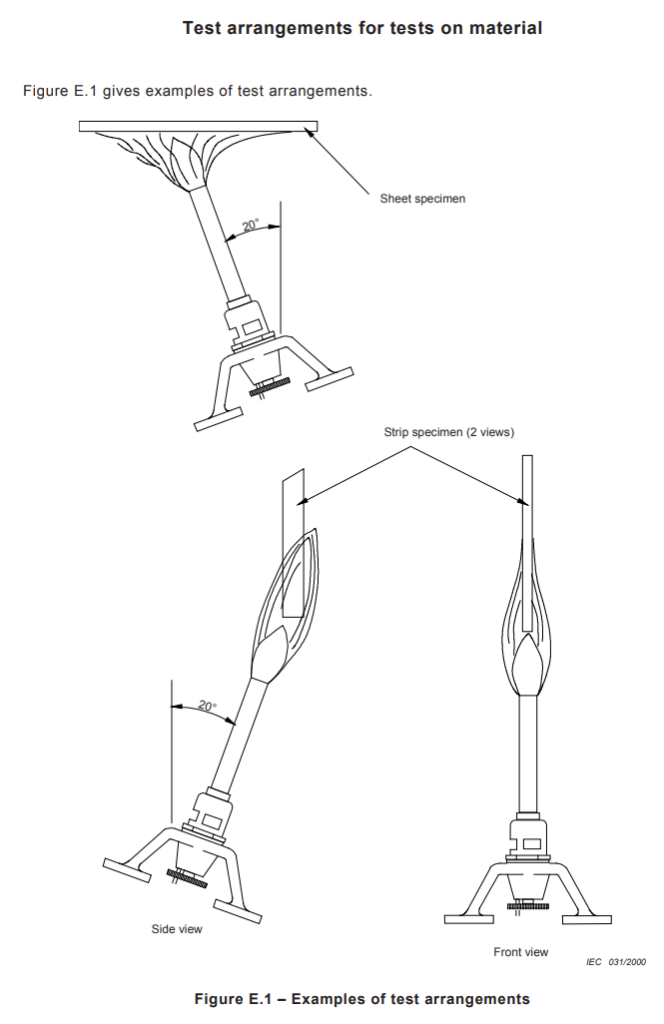
- and thermal confirmation result
must all be considered. The ultimate confirmation is based on the thermal response of a standardized copper block.
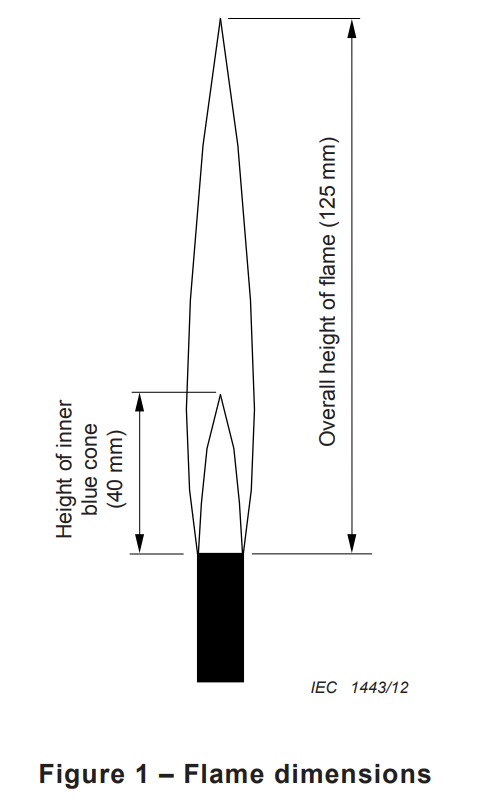
3. Flame Geometry
Both Method A and Method C produce approximately the same specified flame geometry.
Overall Flame Height Approximately 125 mm
Inner Blue Cone Height Approximately 40 mm
The standard’s Figure 1 defines these two primary flame dimensions.
During calibration, the flame shall also be:
- stable;
- symmetrical;
- correctly premixed;
- and capable of satisfying the specified copper-block heating test.
4. Overview of Method A
Method A is based on existing adjustable burner hardware.
The burner uses: Methane ≥98 % purity with a specified gas flow and back pressure.
The burner includes an adjustable air inlet, which is used to establish the required inner blue cone.
The principal operating values are: Methane Flow 965 ± 30 ml/min corrected to: 23 °C and 0.1 MPa
Gas Back Pressure 125 ± 5 mm water column
Inner Blue Cone approximately 40 mm
Overall Flame Height approximately 125 mm
Confirmational Heating Time 54 ± 2 s
for the copper block to increase from: 100 ± 2 °C to 700 ± 3 °C
5. Method A – Burner Construction
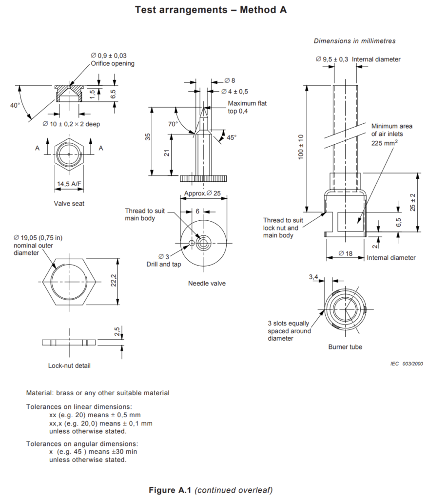
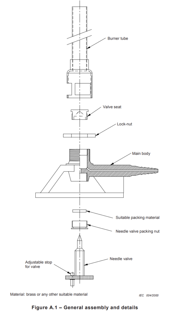
The Method A burner consists essentially of:
- burner tube;
- valve seat / gas injector;
- lock nut;
- main body;
- needle valve;
- needle-valve packing;
- needle-valve packing nut;
- adjustable needle-valve stop;
- adjustable air inlet.
The burner tube, gas injector and needle valve can be removed for cleaning. During reassembly, particular care must be taken to avoid:
- damage to the needle-valve tip;
- misalignment of the needle valve;
- misalignment between the needle valve and valve seat.
These conditions can affect gas regulation and consequently alter flame geometry and thermal output.
6. Method A – Burner Tube Dimensions
The detailed Method A burner drawing specifies:
Burner Tube Internal Diameter Ø 9.5 ± 0.3 mm
Burner Tube Length 100 ± 10 mm
Lower Internal Diameter Ø 18 mm
Air Inlet Three slots are: equally spaced around the burner diameter
The minimum total air-inlet area is: 225 mm²
The adjustable air inlet enables the operator to control the premixed air/fuel condition and consequently the inner blue cone height.
7. Method A – Gas Injector
The specified gas orifice diameter is: Ø 0.9 ± 0.03 mm
The detailed valve-seat geometry also specifies:
- a 40° feature;
- Ø10 ± 0.2 mm × 2 mm deep geometry;
- other specified machining dimensions;
- maximum flat at the top of the needle/seat region: 0.4 mm.
The exact geometry is important because gas velocity and mixing behaviour are directly influenced by the injector.
8. Method A – Burner Material and General Tolerances
The burner is manufactured from: brass or another suitable material
Unless otherwise stated, Method A burner drawing tolerances are:
For dimensions shown as whole numbers: ±0.5 mm
For dimensions shown to one decimal place: ±0.1 mm
For angular dimensions: ±30 minutes
unless a specific tolerance is separately given.
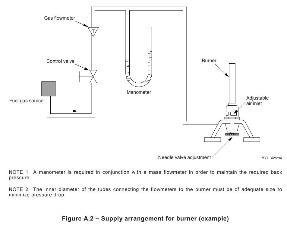
9. Method A – Gas Supply Arrangement
The typical gas supply arrangement consists of:
Fuel Gas Source → Control Valve → Gas Flowmeter → Manometer → Burner
The burner then provides:
- needle-valve adjustment;
- adjustable air inlet.
The tubing between the flowmeter and burner shall have sufficient internal diameter to minimize pressure drop. All gas connections shall be leak-free.
10. Method A – Methane Requirements
Method A uses: Methane with minimum purity: 98 %
Required gas flow: 965 ± 30 ml/min at the reference conditions: 23 °C and 0.1 MPa
Where measurements are made under actual laboratory conditions, they must be corrected to the specified reference conditions.
11. Method A – Flowmeter
The gas flowmeter shall be appropriate for measuring: 965 ml/min methane
at: 23 °C and 0.1 MPa with a tolerance of: ±2 %
A mass flowmeter is the preferred method for accurately controlling the fuel input.
Alternative methods may be used where equivalent accuracy can be demonstrated.
12. Method A – Manometer
The manometer shall be suitable for measuring: 0 to 7.5 kPa
A water manometer may be used when adapted to cover this range.
For Method A, pressure measurement is particularly important because the specified gas condition includes a burner back pressure of: 125 ± 5 mm water column
When a mass flowmeter is used, a manometer is still required to maintain the required back pressure.
13. Method A – Control Valve
A control valve is required to establish the gas flow.
The complete adjustment of Method A therefore involves interaction between:
- external gas-flow control;
- gas back pressure;
- burner needle valve;
- and adjustable air inlet.
The final flame is accepted based on both geometry and thermal confirmation.
14. Method A – Flame Production
The burner supply system is assembled according to the specified Method A arrangement.
All connections shall be checked to ensure they are leak-free. The burner is installed in the laboratory chamber. The methane is ignited.
Gas flow and back pressure are adjusted to: 965 ± 30 ml/min and: 125 ± 5 mm H₂O respectively.
The air inlet is then adjusted until the inner blue cone is approximately: 40 mm
The air inlet is locked in position using the lock nut.
The resulting flame shall appear: stable and symmetrical
15. Method A – Calibration Flame Dimensions
During the confirmational procedure, the inner blue cone is adjusted more precisely to: 40 ± 2 mm using the specified flame-height gauge.
The overall flame height shall be approximately: 125 mm The air inlet is then locked. Before thermal measurement, the operator verifies:
- gas flow;
- gas back pressure;
- blue-cone height;
- flame symmetry.
16. Method C – Operating Principle
Method C takes a different engineering approach. Rather than relying on adjustable burner hardware to entrain and regulate air, it uses: non-adjustable burner hardware
with independent supplies for:
- fuel gas;
- compressed air.
The burner was specifically developed to provide a highly repeatable and stable 500 W flame.
Method C can operate using: methane
or: propane.
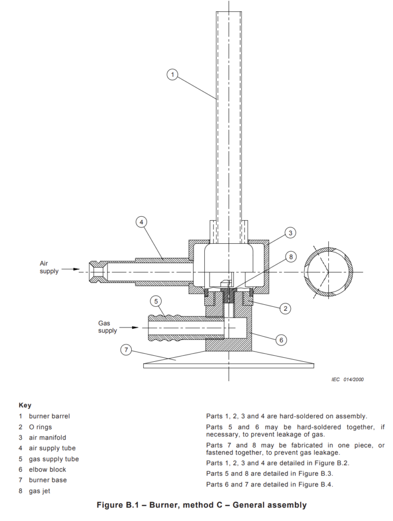
17. Method C – Burner Assembly
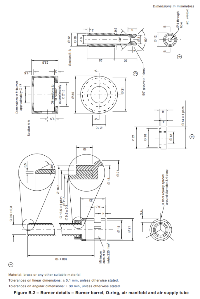
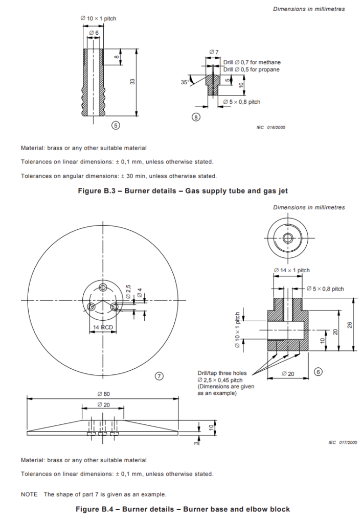
The Method C burner consists of eight principal components:
- Burner barrel
- O-rings
- Air manifold
- Air supply tube
- Gas supply tube
- Elbow block
- Burner base
- Gas jet
The assembly is specifically designed to control mixing without an adjustable burner air inlet. Parts 1, 2, 3 and 4 are hard-soldered during assembly.
Parts 5 and 6 may be hard-soldered together where necessary to prevent gas leakage. Parts 7 and 8 may either:
- be fabricated as a single piece;
- or be securely joined to prevent gas leakage.
18. Method C – Burner Barrel
The burner barrel has the principal dimensions: Internal Diameter Ø 9.5 ± 0.3 mm Length 100 ± 10 mm
The air manifold provides air through: 3 slots equally spaced around the diameter
with a minimum total air-inlet area of: 225 mm²
The detailed construction also includes the O-ring, air manifold and air supply tube geometry specified in the standard.
19. Method C – Burner Material and Tolerances
The Method C burner components are specified as: brass or another suitable material
For the detailed burner components, unless otherwise specified: Linear Tolerance ±0.1 mm Angular Tolerance ±30 minutes
This is an important distinction from some of the general dimensional tolerances shown for the Method A burner.
20. Method C – Gas Jet
Method C uses different gas-jet drilling depending on fuel.
Methane Jet Ø 0.7 mm
Propane Jet Ø 0.5 mm
The jet drawing also specifies:
- 35° geometry;
- Ø5 × 0.8 pitch thread;
- Ø10 × 1 pitch features;
- associated length and machining dimensions.
Correct selection of the jet is essential because methane and propane require different volumetric flow rates.
21. Method C – Methane Operating Conditions
When Method C is operated with methane:
Methane Purity ≥98 %
Methane Flow 965 ± 30 ml/min at: 23 °C and 0.1 MPa
Air Flow 6.3 ± 0.1 l/min at: 23 °C and 0.1 MPa
Expected Methane Back Pressure 110–170 mm water
Expected Air Back Pressure 20–40 mm water
These pressure ranges are expected operating values rather than the principal flow-setting criteria.
22. Method C – Propane Operating Conditions
When Method C is operated with propane:
Propane Purity ≥98 %
Propane Flow 380 ± 15 ml/min at: 23 °C and 0.1 MPa
Air Flow 5.9 ± 0.1 l/min at: 23 °C and 0.1 MPa
Expected Propane Back Pressure 135–205 mm water
Expected Air Back Pressure 15–35 mm water
23. Methane Requirement in Case of Dispute
Although Method C permits either methane or propane during normal use, IEC 60695-11-3 specifies that:
in cases of dispute, methane shall be used
with a purity of at least: 98 %
This is an important requirement when results from different laboratories or parties need to be formally compared.
24. Method C – Air Supply Quality
The compressed air supplied to the Method C burner shall be essentially free from:
- oil;
- water.
Contamination of the air supply can affect burner operation, mixture characteristics and repeatability.
25. Method C – Flowmeters
Separate measurement is required for:
- fuel flow;
- air flow.
Fuel flowmeters shall measure: Methane 965 ml/min or: Propane 380 ml/min at the specified reference conditions.
Air flowmeters shall measure: Methane configuration 6.3 l/min or: Propane configuration 5.9 l/min
Required flow measurement tolerance: ±2 %
Mass flowmeters are preferred for accurate control of both fuel and air.
26. Method C – Manometers
Where conventional flow measurement is used, two manometers are required:
- one for fuel;
- one for air.
Each shall be suitable for: 0–7.5 kPa
Water manometers may be used. However, unlike Method A:
manometers are not required when mass flowmeters are used for Method C.
27. Method C – Control Valves
Two control valves are required: Gas Control Valve
for fuel-flow adjustment. Air Control Valve for air-flow adjustment.
This permits independent establishment of the specified gas and air flow rates.
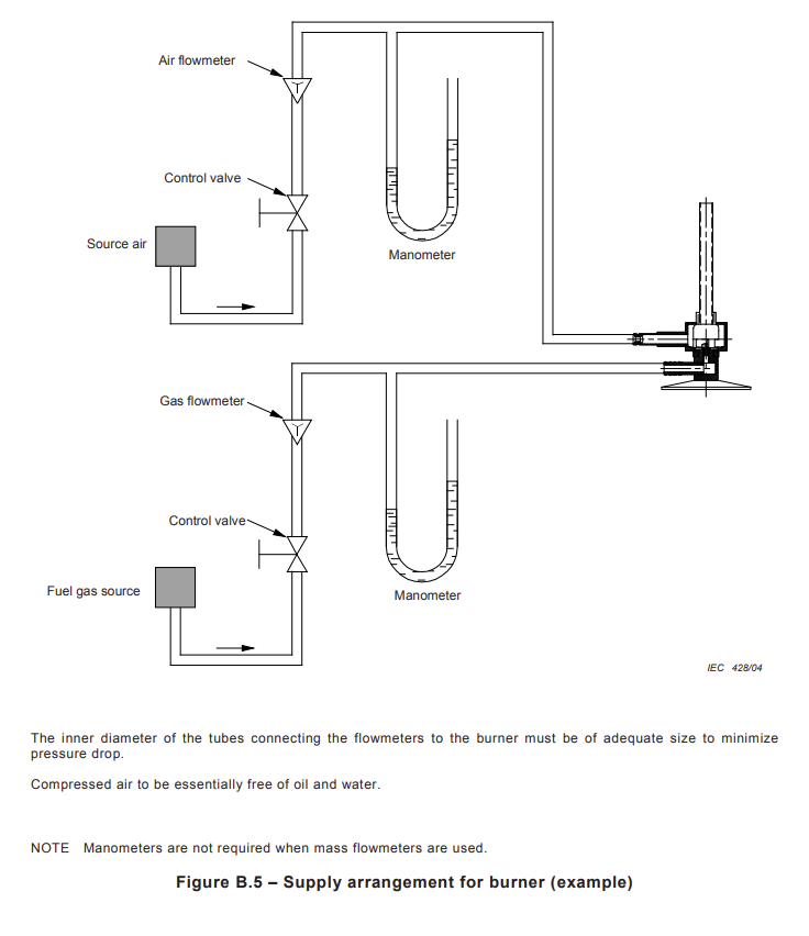
28. Method C – Supply Arrangement
The Method C supply arrangement contains two separate circuits.
Air Circuit
Air Source → Control Valve → Air Flowmeter → Pressure Measurement → Burner
Fuel Circuit
Fuel Source → Control Valve → Gas Flowmeter → Pressure Measurement → Burner
The internal diameter of connecting tubes shall be sufficient to minimize pressure drop. The compressed air shall remain essentially free from oil and water.
29. Method C – Flame Production
Assemble the burner supply arrangement and verify that all gas and air connections are leak-free. Place the burner inside the laboratory chamber.
Ignite the mixture.
Adjust the gas and air flow rates to the appropriate values for either:
- methane operation;
- or propane operation.
The resulting flame shall have: Inner blue cone ≈ 40 mm Overall flame height ≈ 125 mm and shall appear: stable and symmetrical
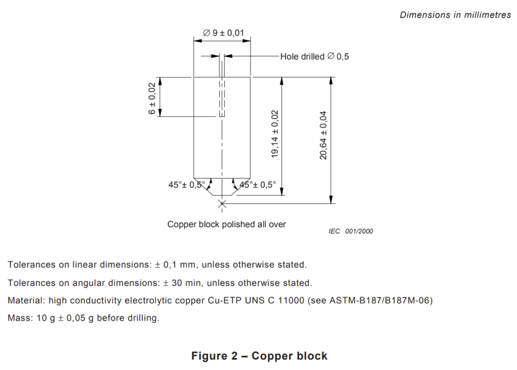
30. Copper Confirmation Block
Both Method A and Method C use the same standardized copper block for thermal confirmation.
Material High-conductivity electrolytic copper: Cu-ETP / UNS C11000
Diameter Ø 9 ± 0.01 mm
Mass Before Drilling 10.00 ± 0.05 g
Thermocouple Hole Ø 0.5 mm
Principal Drawing Dimensions
19.14 ± 0.02 mm
20.64 ± 0.04 mm
6 ± 0.02 mm
Lower Angles 45° ± 0.5°
The block shall be: polished all over
Unless otherwise specified: Linear Tolerance ±0.1 mm
Angular Tolerance ±30 min
31. Copper Block Reference Control
IEC 60695-11-3 does not define a separate verification procedure for the copper block itself.
Laboratories are encouraged to maintain:
- a standard reference unit;
- a secondary standard reference unit;
- a working unit.
Cross-comparison can then be used to verify the working system.
This is important because variations in:
- copper mass;
- geometry;
- material;
- machining;
- surface condition;
- thermocouple installation
can influence heating time.
32. Thermocouple Requirements
Both methods use a: mineral-insulated, metal-sheathed fine-wire thermocouple
with: insulated junction
The thermocouple shall be: IEC 60584-2 Class 1
Nominal overall diameter: 0.5 mm
An example is: Type K – NiCr/NiAl
according to IEC 60584-1. The welded point is located inside the sheath.
33. Thermocouple Temperature Capability
The thermocouple sheath shall consist of a metal capable of continuous operation at: at least 1,050 °C
A suitable nickel-based heat-resistant alloy can satisfy this requirement. This high-temperature capability is necessary even though the confirmational measurement ends at 700 °C.
34. Thermocouple Installation in the Copper Block
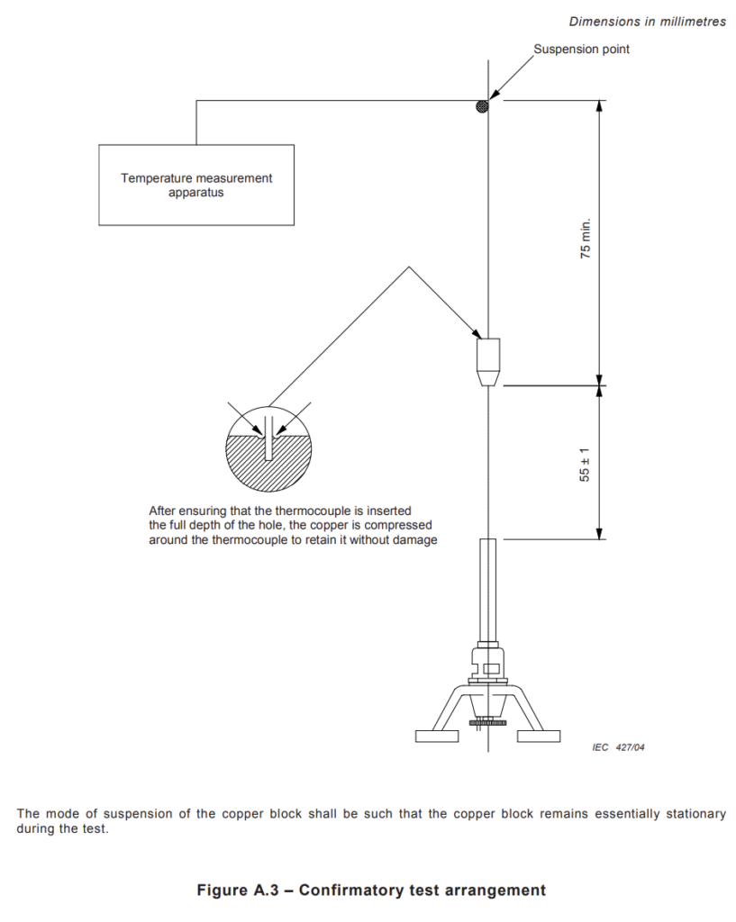
The thermocouple shall first be inserted to: the full depth of the drilled hole
The preferred retention method is then to: compress the copper around the thermocouple
so that it is securely retained without damaging the sensor. This arrangement is shown in both Method A and Method C confirmational test diagrams.
35. Temperature and Time Measurement
The temperature/time indicating or recording system shall be capable of determining the time required for the copper block to rise from: 100 ± 2 °C to: 700 ± 3 °C
The tolerance on measured time shall be: ±0.5 s
The recording system therefore needs sufficient:
- temperature accuracy;
- response;
- sampling performance;
- time resolution
to determine this heating interval reliably.
36. Laboratory Fumehood / Chamber
Both methods require a laboratory chamber with an internal volume of at least: 0.75 m³
The chamber shall:
- permit observation of the test;
- provide a draught-free environment;
- allow normal thermal circulation of air around the specimen;
- have dark-coloured internal walls.
The chamber is an integral part of the test system because airflow can substantially affect a 125 mm premixed flame.
37. Chamber Illumination
A lux meter is positioned at the flame location and directed toward the rear of the chamber.
The measured background illumination shall be: <20 lx
This provides appropriate conditions for visual evaluation of the flame.
38. Chamber Extraction System
The enclosure may be equipped with an extraction device such as an exhaust fan to remove combustion products.
However: Extraction shall be OFF during the test.
Immediately after the test: Extraction shall be switched ON
to remove potentially toxic fire effluents.
A positive-closing damper may be required.
39. Chamber Oxygen Availability
The standard specifically notes that oxygen availability is important during flame testing.
For tests involving prolonged burning: a 0.75 m³ chamber may not necessarily be sufficient
to produce accurate results.
Therefore, chamber volume should not be interpreted independently from the combustion duration and oxygen demand of the actual test.
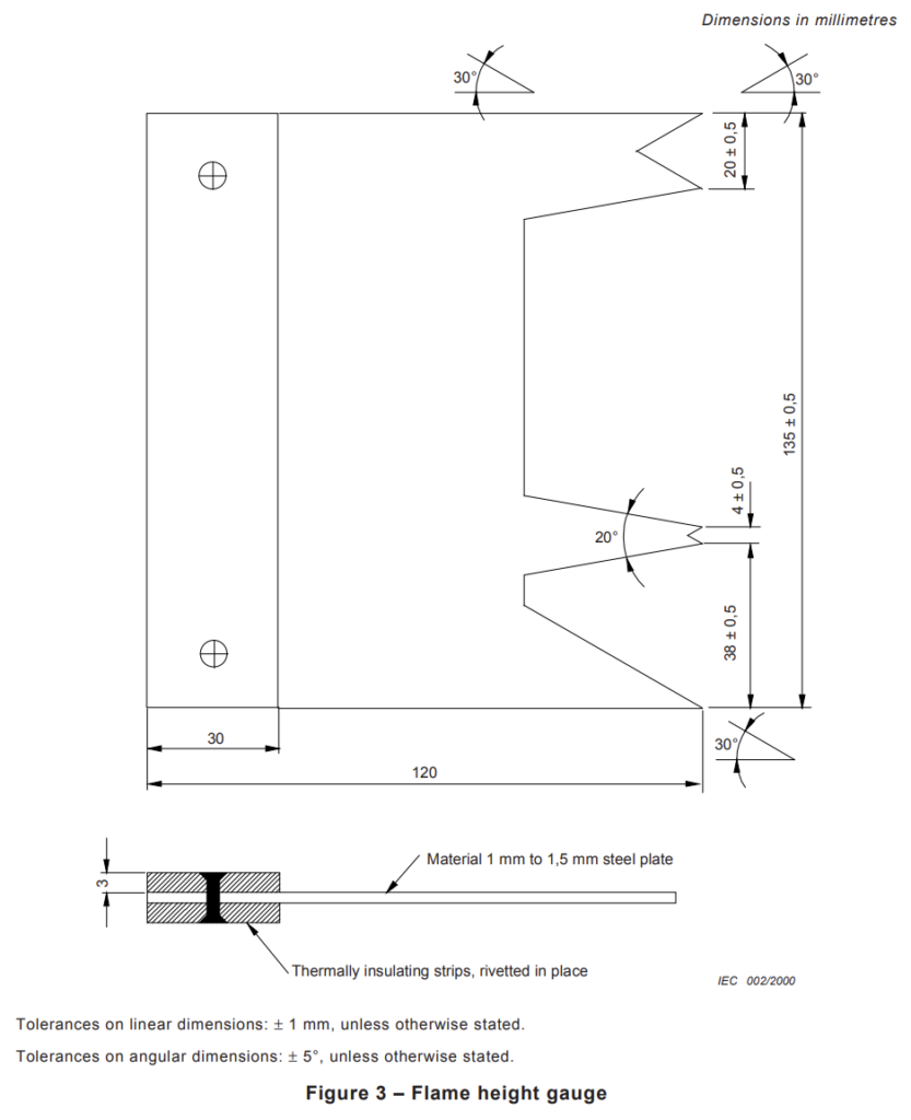
40. Flame Height Gauge
The flame-height gauge is used to establish the required:
- 40 mm inner blue cone;
- 125 mm overall flame height.
The gauge is manufactured from: 1.0 to 1.5 mm steel plate
and incorporates thermally insulating strips.
Principal dimensions include:
- overall reference height: 135 ± 0.5 mm
- gauge width: 30 mm
- reach: 120 mm
- reference sections including 20 ± 0.5 mm, 38 ± 0.5 mm, and 4 ± 0.5 mm
- specified 20° and 30° reference angles.
Unless otherwise stated, gauge tolerances are: Linear ±1 mm Angular ±5°
41. Principle of Thermal Confirmation
The flame is not finally accepted by visual inspection.
The standard uses a quantitative thermal test.
The standardized copper block is suspended above the burner.
The burner is positioned according to the relevant confirmational arrangement.
The measurement system records the time required for the copper block to increase from:100 ± 2 °C to: 700 ± 3 °C
The required result for both methods is: 54 ± 2 seconds
Therefore, each acceptable determination must fall within: 52–56 seconds
42. Confirmational Test Geometry
For both Method A and Method C, the copper block shall be suspended so that it remains essentially stationary during the test. The confirmational drawings specify:
Minimum Suspension Dimension 75 mm minimum
Burner-to-Block Reference Dimension 55 ± 1 mm
The burner is positioned directly below the copper block according to the specified geometry.
Method A uses the arrangement shown for its adjustable burner.
Method C uses the corresponding arrangement for the non-adjustable burner.
43. Method A – Complete Confirmation Procedure
Step 1 – Assemble the System
Set up the burner supply and confirmation arrangement. Place it inside the specified chamber. Ensure that all gas connections are leak-free.
Step 2 – Move Burner Away from Copper Block
Temporarily remove the burner from beneath the copper block. This prevents preliminary flame adjustment from influencing the block temperature.
Step 3 – Ignite Methane
Ignite the gas.
Step 4 – Adjust Gas Flow
Set methane flow to: 965 ± 30 ml/min at the specified reference conditions.
Step 5 – Adjust Back Pressure
Set: 125 ± 5 mm H₂O
Step 6 – Adjust Inner Blue Cone
Adjust the burner air inlet until the blue cone is: 40 ± 2 mm
Step 7 – Lock Air Adjustment
Secure the air inlet using the lock nut.
Step 8 – Verify Overall Flame
Confirm: overall flame height ≈125 mm
and ensure that the flame is symmetrical.
Step 9 – Stabilize Burner
Allow the burner to operate for at least: 5 minutes to reach equilibrium.
Step 10 – Recheck Parameters
Confirm that:
- gas flow;
- gas back pressure;
- blue-cone height
remain within the prescribed limits.
Step 11 – Begin Thermal Test
Ensure that the temperature/time measurement system is operating.
Move the burner back underneath the copper block.
Step 12 – Measure Heating Time
Measure the time required for: 100 ± 2 °C → 700 ± 3 °C
Required: 54 ± 2 s
44. Method C – Complete Confirmation Procedure
Step 1 – Assemble Burner and Supply System
Set up the Method C burner according to the specified confirmation arrangement.
Ensure:
- gas connections are leak-free;
- air connections are leak-free.
Step 2 – Move Burner Away
Keep the flame away from the copper block during preliminary adjustment.
Step 3 – Ignite the Mixture
Ignite the selected fuel/air mixture.
Step 4 – Establish Flow Rates
For methane: Gas = 965 ± 30 ml/min Air = 6.3 ± 0.1 l/min
For propane: Gas = 380 ± 15 ml/min Air = 5.9 ± 0.1 l/min
Step 5 – Verify Flame Dimensions
Using the flame-height gauge, verify:
inner blue cone ≈40 mm
overall flame ≈125 mm
and ensure flame symmetry.
Step 6 – Stabilization
Wait at least: 5 minutes
for burner equilibrium.
Step 7 – Recheck Flow Rates
Measure the fuel and air flows again and verify that they remain within the specified limits.
Step 8 – Position Burner
With the temperature/time recorder operating, move the burner beneath the copper block.
Step 9 – Record Heating Time
Measure: 100 ± 2 °C → 700 ± 3 °C
Required result: 54 ± 2 s

45. Three Successive Results Are Mandatory
For both methods, one compliant result is not sufficient.
After obtaining an acceptable result: repeat the procedure twice
until: three successive determinations
are within: 54 ± 2 s
Therefore:
52 s ≤ Test 1 ≤ 56 s
52 s ≤ Test 2 ≤ 56 s
52 s ≤ Test 3 ≤ 56 s
and the results must be consecutive.
46. Cooling Between Confirmational Tests
Between determinations, allow the copper block to cool: naturally in air
until its temperature is: below 50 °C
Only then should another determination be performed.
47. Failed Confirmation Result
If any determination is outside: 54 ± 2 s
the flame shall be adjusted accordingly.
After adjustment:
- allow the burner to return to equilibrium;
- restart the confirmation procedure.
The requirement is not an average of several measurements.
It is: three successive compliant determinations.
48. Conditioning a New Copper Block
When a copper block is used for the first time:
perform one preliminary heating cycle.
This conditions the block surface.
The result shall be:
discarded
and shall not count as one of the three confirmational measurements.
49. Protection of the Thermocouple
The thermocouple may be easily damaged at temperatures above: 700 °C
It is therefore advisable to remove the burner immediately after the block reaches 700 °C.
50. Final Acceptance Criterion
For either Method A or Method C, the flame is confirmed and may be used for testing only when:
Temperature Range 100 ± 2 °C → 700 ± 3 °C
Heating Time 54 ± 2 s
Number of Required Results
3 successive compliant determinations
Cooling Between Runs Natural cooling to <50 °C
Burner Stabilization Before Measurement At least 5 minutes
This thermal confirmation provides the practical verification that the complete burner system is producing the required standardized 500 W flame.
51. Classification and Apparatus Designation
An apparatus satisfying Method A may be identified as:
“500 W nominal test flame apparatus – Method A, conforming to IEC 60695-11-3.”
An apparatus satisfying Method C may be identified as:
“500 W nominal test flame apparatus – Method C, conforming to IEC 60695-11-3.”
52. Method A vs Method C – Technical Comparison
| Parameter | Method A | Method C – Methane | Method C – Propane |
|---|---|---|---|
| Nominal flame | 500 W | 500 W | 500 W |
| Flame type | Premixed | Premixed | Premixed |
| Burner | Adjustable | Non-adjustable | Non-adjustable |
| Fuel | Methane | Methane | Propane |
| Fuel purity | ≥98 % | ≥98 % | ≥98 % |
| Fuel flow | 965 ± 30 ml/min | 965 ± 30 ml/min | 380 ± 15 ml/min |
| Air supply | Burner air inlet | 6.3 ± 0.1 l/min | 5.9 ± 0.1 l/min |
| Fuel back pressure | 125 ± 5 mm H₂O | Expected 110–170 mm H₂O | Expected 135–205 mm H₂O |
| Air back pressure | — | Expected 20–40 mm H₂O | Expected 15–35 mm H₂O |
| Inner blue cone | 40 mm | 40 mm | 40 mm |
| Overall flame | 125 mm | 125 mm | 125 mm |
| Copper block | 10.00 ± 0.05 g | Same | Same |
| Confirmation | 54 ± 2 s | 54 ± 2 s | 54 ± 2 s |
53. Recommended Arrangement for Equipment Testing
When either standardized 500 W flame is used for testing equipment, unless the relevant product specification states otherwise, the recommended distance from: the top of the burner tube
to: the test point on the specimen surface
is approximately: 55 mm
The burner is fixed in position during the test.
The 55 mm distance was selected to improve reproducibility compared with trying to position the inner blue cone tip immediately adjacent to the specimen.
54. Why the 55 mm Distance Is Used
The standard notes that the 55 mm burner-to-specimen distance provides better reproducibility than attempting to position the flame so that: the tip of the inner blue cone just does not touch the specimen
which corresponds approximately to a separation of: 0–3 mm
between the inner cone tip and specimen. For equipment testing, the fixed 55 mm burner reference is therefore recommended.
55. Bar Test Specimens
For bar-shaped specimens, the test arrangement is different.
The operator may move the burner to follow a specimen that:
- burns;
- bends;
- distorts.
In this case:
the tip of the inner blue cone should just not touch the specimen
corresponding to approximately: 0–3 mm clearance
The burner is tilted so that falling debris does not enter the burner.
56. Equipment Test Orientation
The informative equipment test diagrams illustrate multiple application configurations.
Examples include flame application to:
- curved surfaces;
- vertical surfaces;
- edges or lower surfaces.
The illustrated arrangements use a burner inclination of approximately: 20°
with the indicated: 55 mm
reference distance. The relevant product specification ultimately determines the actual application geometry.
57. Material Test Arrangements
The standard also provides examples for:
- sheet specimens;
- strip specimens.
The informative drawings show possible burner orientations for applying the standardized 500 W flame to these material configurations.
An inclination of approximately: 20°
is illustrated for some arrangements.
Again, these figures provide recommended arrangements; the applicable material or product standard determines the actual test conditions and acceptance criteria.
58. Critical Distinction: Flame Standard vs Product Flammability Test
IEC 60695-11-3 primarily defines the: 500 W standardized flame source
and its: confirmation method.
It does not establish one universal pass/fail requirement for every product or material.
A product-specific or material-specific standard must define parameters such as:
- specimen dimensions;
- specimen conditioning;
- orientation;
- exact flame application location;
- burner angle;
- application time;
- number of flame applications;
- afterflame time;
- afterglow time;
- dripping behaviour;
- ignition of surrounding materials;
- damage criteria;
- classification;
- final pass/fail criteria.
Therefore: IEC 60695-11-3 apparatus conformity ≠ automatic product conformity.
The standardized flame is the controlled ignition source used by another applicable test method.
59. Essential Pre-Test Verification Checklist
Before using the apparatus for an actual fire-hazard test, verify:
Common Requirements
✓ Correct IEC 60695-11-3 burner method selected
✓ Burner geometry compliant
✓ Burner clean and undamaged
✓ Correct fuel selected
✓ Fuel purity ≥98 %
✓ Flow measurement tolerance ±2 %
✓ Leak-free connections
✓ Correct flame-height gauge
✓ Inner blue cone approximately 40 mm
✓ Overall flame approximately 125 mm
✓ Stable and symmetrical flame
✓ Correct copper block
✓ Copper block 10.00 ± 0.05 g before drilling
✓ Copper block Ø9 mm
✓ Correct 0.5 mm thermocouple
✓ Thermocouple IEC 60584-2 Class 1
✓ Thermocouple fully inserted
✓ Correct temperature/time measurement system
✓ Timing tolerance ±0.5 s
✓ Chamber volume ≥0.75 m³
✓ Draught-free environment
✓ Chamber background light <20 lx
✓ Extraction OFF during testing
✓ Burner stabilized ≥5 min
✓ Confirmation result 54 ± 2 s
✓ Three successive compliant determinations
✓ Copper block cooled naturally below 50 °C between runs
Additional Method A Checks
✓ Methane 965 ± 30 ml/min
✓ Back pressure 125 ± 5 mm H₂O
✓ Adjustable air inlet correctly set
✓ Air-inlet lock nut secured
✓ Inner blue cone 40 ± 2 mm during confirmation
Additional Method C Checks
✓ Correct methane or propane gas jet installed
✓ Correct fuel flow selected
✓ Correct air flow selected
✓ Air supply essentially free from oil and water
✓ Separate gas and air circuits correctly connected
✓ Correct flowmeters for both circuits
60. Engineering Significance of the Confirmation Test
One of the most important concepts behind IEC 60695-11-3 is that: flame geometry alone does not prove thermal equivalence.
Two flames can both have:
- a 40 mm inner blue cone;
- a 125 mm overall height;
while still transferring different amounts of heat.
Possible causes include:
- incorrect fuel flow;
- inaccurate air flow;
- incorrect burner geometry;
- injector variation;
- incorrect gas jet;
- gas composition;
- fuel pressure;
- air pressure;
- contamination;
- burner temperature;
- environmental airflow;
- measurement errors.
For this reason, the standardized flame is ultimately verified by its effect on a precisely defined thermal reference.
That reference is the 10 g copper block.
A compliant flame must repeatedly heat that block from: 100 °C to 700 °C
in approximately: 54 seconds.
61. The Complete IEC 60695-11-3 Control Philosophy
The engineering logic of the standard can be summarized as:
Control the burner geometry
↓
Control the fuel quality
↓
Control the fuel flow
↓
Control the air supply / burner air inlet
↓
Control the pressure conditions
↓
Establish the specified flame geometry
↓
Allow the burner to reach thermal equilibrium
↓
Verify the 40 mm inner blue cone
↓
Verify the approximately 125 mm overall flame
↓
Measure thermal performance using the standardized copper block
↓
Obtain 54 ± 2 s
↓
Repeat until three successive results comply
↓
Use the confirmed flame for the applicable fire-hazard test
This is why a properly designed 500 W flame-test apparatus is more than simply a burner and a gas-flow controller. It is a complete controlled thermal test system.
500W Flame Tester According IEC 60695-11-3
- Digital timer
- Rotameter type flow controller
- Gas pressure indicator
- Automatic flame application on sample piece
- Chamber size according to the standard
- Sample positioning 2 axes linear mechanism
- Copper block and measurement unit with WINDOWS software for verification of flame is as option (Not included in standard delivery)
- Nominal flame power: 500 W
- Flame type: Premixed
- Overall flame height: ≈125 mm
- Inner blue cone: ≈40 mm
- Copper block diameter: Ø9 ± 0.01 mm
- Copper block mass: 10.00 ± 0.05 g before drilling
- Thermocouple hole: Ø0.5 mm
- Thermocouple: 0.5 mm, Class 1
- Temperature interval: 100 ± 2 °C → 700 ± 3 °C
- Required heating time: 54 ± 2 s
- Acceptable heating interval: 52–56 s
- Required confirmation: 3 successive compliant tests
- Cooling between runs: naturally to <50 °C
- Burner stabilization: ≥5 min
- Minimum chamber volume: 0.75 m³
- Background illumination: <20 lx
- Recommended equipment distance: ≈55 mm
Method A
- Fuel: Methane (to be supplied by customer)
- Purity: ≥98 %
- Fuel flow: 965 ± 30 ml/min
- Back pressure: 125 ± 5 mm H₂O
- Flowmeter tolerance: ±2 %
- Manometer range: 0–7.5 kPa
- Burner tube ID: 9.5 ± 0.3 mm
- Burner tube length: 100 ± 10 mm
- Gas orifice: Ø0.9 ± 0.03 mm
- Minimum air-inlet area: 225 mm²
Method C – Methane
- Fuel: Methane (to be supplied by customer)
- Purity: ≥98 %
- Fuel flow: 965 ± 30 ml/min
- Air flow: 6.3 ± 0.1 l/min
- Expected fuel back pressure: 110–170 mm H₂O
- Expected air back pressure: 20–40 mm H₂O
- Gas jet: Ø0.7 mm
Method C – Propane
- Fuel: Propane (to be supplied by customer)
- Purity: ≥98 %
- Fuel flow: 380 ± 15 ml/min
- Air flow: 5.9 ± 0.1 l/min
- Expected fuel back pressure: 135–205 mm H₂O
- Expected air back pressure: 15–35 mm H₂O
- Gas jet: Ø0.5 mm