
Introduction
ASTM F2418 – Standard Specification for Polypropylene (PP) Corrugated Wall Stormwater Collection Chambers establishes material requirements, dimensional requirements, mechanical performance criteria, test procedures, sampling rules, acceptance criteria, and marking requirements for polypropylene underground stormwater chambers.
These chambers are open-bottom, arch-shaped thermoplastic structures designed for underground collection, detention, and retention of stormwater.
Typical applications include:
- Commercial drainage systems
- Residential stormwater systems
- Agricultural drainage
- Highway drainage
- Parking areas
- Roadways
- Underground stormwater retention systems
- Underground infiltration and detention installations
Because these chambers are installed below ground and are continuously exposed to soil loads, traffic loads, installation stresses, environmental ageing, and long-term polymer creep, ASTM F2418 evaluates both short-term structural performance and long-term material behaviour.
The major qualification requirements include:
- Polypropylene material properties
- Chamber dimensions
- Wall thickness
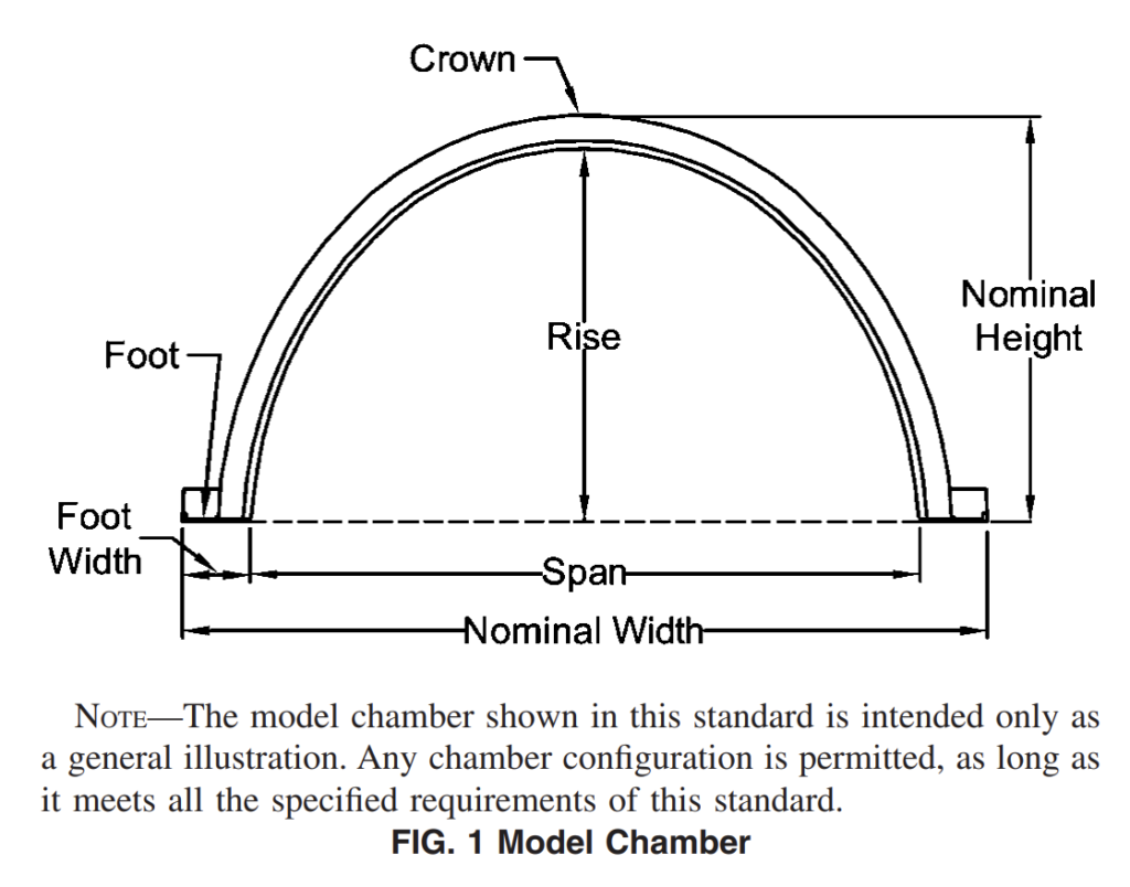
- Foot width
- Rise and span
- Straightness
- 50-year creep rupture strength
- 50-year creep modulus
- Arch Stiffness Constant (ASC)
- Flattening resistance
- Accelerated UV weathering
- Full-scale installation qualification
1. Construction of the Stormwater Chamber
The chamber is an arch-shaped structure having an open bottom.
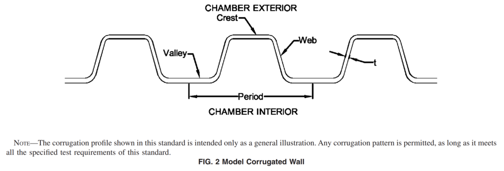
The main structural features are:
- Crown
- Corrugated wall
- Crests
- Valleys
- Webs
- Integral feet
- End connections
- Optional inspection ports
- Optional perforations
The maximum chamber span occurs at the base of the chamber.
The feet provide the bearing surfaces through which vertical chamber loads are transferred to the bedding and foundation.
Chamber sections may be joined together longitudinally to create rows of different lengths.
The joints must:
- Prevent intrusion of surrounding embedment material
- Maintain chamber alignment
- Carry the full structural load for which the chamber is designed
Each row begins and terminates with an end cap.
2. Polypropylene Material Requirements
The chamber and end-cap material must comply with the applicable polypropylene classification requirements.
The material classification specified by ASTM F2418 is: PP0330B99945 according to ASTM D4101
The polypropylene content of the material must be at least: 95% by weight
The polymer formulation may include appropriate:
- Copolymers
- Pigments
- Impact modifiers
- Processing additives
provided the final material and chamber satisfy all requirements of ASTM F2418.
3. Reworked Material
Clean reworked polypropylene generated from the manufacturer’s own chamber production may be reused.
However:
- The rework must originate from the same manufacturer.
- The same type and grade of resin must be used.
- The finished chamber must continue to satisfy every requirement of ASTM F2418.
Use of rework does not reduce any acceptance requirement.
4. Minimum Tensile Yield Strength
The PP material must be tested according to:
ASTM D638 – Tensile Properties of Plastics
The minimum tensile stress at yield is: 21 MPa
or: 3100 psi
Therefore:
Tensile Stress at Yield ≥ 21 MPa → PASS
Tensile Stress at Yield < 21 MPa → FAIL
The tensile test equipment should consist of a calibrated universal testing machine equipped with:
- Appropriate tensile grips
- Calibrated load cell
- Controlled crosshead movement
- Suitable extensometer where required
- Data acquisition system
5. Minimum Flexural Modulus
Flexural modulus must be determined according to: ASTM D790 – Procedure A
The specified property is the: 1% Secant Flexural Modulus
Minimum acceptable value: 1000 MPa
or: 145,000 psi
Therefore:
Flexural Modulus ≥ 1000 MPa → PASS
6. Izod Impact Resistance
Impact resistance is evaluated according to: ASTM D256 – Method A
Test temperature: 23 °C
Minimum impact resistance: 215 J/m
or: 4 ft-lb/in
Therefore: Izod Impact Resistance ≥ 215 J/m → PASS
Testing should be performed using a calibrated pendulum impact tester with the required:
- Pendulum capacity
- Specimen support
- Striker geometry
- Notching equipment
- Temperature conditioning
7. General Conditioning of Test Specimens
Unless another test method specifies different conditions, specimens must be conditioned according to:
ASTM D618 – Procedure A
Required conditioning environment:
Temperature: 23 ± 2 °C
Relative Humidity: 50 ± 5%
Minimum conditioning duration: 4 hours
Tests should also be conducted under the same temperature and humidity conditions unless the specific test method specifies otherwise.
This requirement is important because PP mechanical properties depend upon temperature.
8. Visual Acceptance of Finished Chambers
Before dimensional or mechanical testing, chambers should be visually inspected.
The product must be essentially homogeneous and reasonably uniform in:
- Colour
- Opacity
- Density
- Surface condition
- Material distribution
The internal and external surfaces must be free from:
- Chalking
- Sticky material
- Tacky surfaces
The chamber wall must also be free from visible:
- Cracks
- Blisters
- Voids
- Foreign inclusions
- Other defects that can impair structural wall integrity
Inspection is made under normal conditions using the unaided eye.
A visible defect capable of affecting chamber integrity constitutes a non-conforming condition.
9. Dimensional Inspection Equipment
A complete dimensional inspection station should preferably include:
- Precision caliper
- Micrometer
- Steel rule
- Measuring tape
- Height gauge
- Flat and level reference table
- Straight edge or tensioned reference line
- Ultrasonic thickness gauge when nondestructive thickness measurement is required
For large stormwater chambers, appropriate large-format fixtures may be required.
10. Chamber Wall Thickness Measurement
Wall thickness is evaluated according to ASTM F2418 with dimensional principles based on ASTM D2122.
Measurements are performed at a minimum of: 2 locations along the longitudinal axis
At each longitudinal location: Minimum 8 circumferential positions
must be measured.
At every circumferential position, four measurements are made across the corrugation profile:
- Valley
- Crest
- First web
- Second web
Therefore, the minimum basic measurement program represents: 2 × 8 × 4 = 64 wall-thickness readings
for a chamber.
The laboratory records:
- Minimum measured thickness
- Average measured thickness
11. Wall Thickness Near Mould Flow Channels
Where mould-flow channels cause local variations in chamber wall thickness, these areas are excluded from the standard wall-thickness measurement.
Instead, thickness is measured in the adjacent flat region.
This avoids treating intentional mould-flow geometry as representative structural wall thickness.
12. End Corrugation Exception
At end corrugations where adjacent chambers or end caps overlap, the required local wall thickness may be reduced.
The allowable thickness can be:
75% of the Table 1 wall-thickness requirement
because these regions form part of an overlapping connection.
This exception applies specifically to the overlap region and should not be generalized to the main chamber wall.
13. Ultrasonic Wall Thickness Measurement
ASTM F2418 permits nondestructive wall-thickness measurement using a:
Properly calibrated ultrasonic thickness gauge
This can be advantageous when destructive sectioning of large chambers is undesirable.
The ultrasonic system should be calibrated using:
- Reference specimens
- Known PP wall thickness
- Appropriate sound velocity setting
Surface coupling and geometry must be carefully controlled.
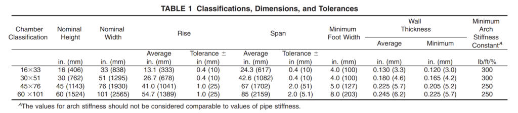
14. Minimum Chamber Wall Thickness
The measured wall thickness must not be less than the minimum applicable value specified for the corresponding chamber classification.
The standard defines classifications such as:
- 16 × 33
- 30 × 51
- 45 × 76
- 60 × 101
The required values depend on chamber size.
16 × 33 Chamber
Average wall thickness: 3.3 mm
Minimum wall thickness: 3.0 mm
30 × 51 Chamber
Average wall thickness: 4.6 mm
Minimum wall thickness: 4.2 mm
45 × 76 Chamber
Average wall thickness: 5.7 mm
Minimum wall thickness: 5.2 mm
60 × 101 Chamber
Average wall thickness: 6.2 mm
Minimum wall thickness: 5.7 mm
Failure to satisfy the minimum wall-thickness requirement constitutes product non-conformance.
15. Foot Width Measurement
Each chamber foot is measured at three locations:
- One end
- Mid-length
- Opposite end
The laboratory reports:
- Minimum foot width
- Average foot width
The minimum measured foot width must satisfy the classification requirement.
16. Minimum Foot Width Requirements
16 × 33 Chamber
Minimum foot width: 100 mm
30 × 51 Chamber
Minimum foot width: 100 mm
45 × 76 Chamber
Minimum foot width: 127 mm
60 × 101 Chamber
Minimum foot width: 203 mm
The chamber foot is structurally important because loads are transmitted from the arch into the bedding through this area.
17. Rise Measurement
The chamber is placed on: A flat and level surface
No external load is applied except the chamber’s own weight. Rise is measured as the vertical distance from the reference surface to the inside face of the valley at the chamber crown.
Measurements are made at:
- First end
- Mid-length
- Second end
The three measurements are averaged.
18. Rise Requirements
Typical average rise requirements specified by ASTM F2418 include:
16 × 33
Average rise: 333 mm
Tolerance: ±10 mm
30 × 51
Average rise: 678 mm
Tolerance: ±10 mm
45 × 76
Average rise: 1041 mm
Tolerance: ±25 mm
60 × 101
Average rise: 1389 mm
Tolerance: ±25 mm
The measured average must remain within the specified tolerance.
19. Span Measurement
Span is measured with the chamber on a: Flat level surface
under self-weight only.
The measurement is taken horizontally between the inside surfaces of the opposing valley elements near the chamber feet.
Measurements are taken at:
- First end
- Mid-length
- Second end
The three values are averaged.
20. Span Requirements
16 × 33 Chamber
Average span: 617 mm
Tolerance: ±10 mm
30 × 51 Chamber
Average span: 1082 mm
Tolerance: ±10 mm
45 × 76 Chamber
Average span: 1702 mm
Tolerance: ±51 mm
60 × 101 Chamber
Average span: 2159 mm
Tolerance: approximately ±51 mm
The average span must satisfy the limits applicable to the chamber classification.
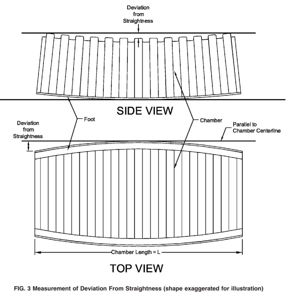
21. Straightness Test
The chamber is positioned on a flat and level reference surface under its own weight.
Three straightness measurements are required:
- One along the crown
- One along the first foot
- One along the second foot
A straight reference line is established between the two ends of the component being measured.
The maximum deviation between the chamber surface and the theoretical straight line is determined.
22. Acceptance Criterion for Straightness
Maximum permissible deviation is: L / 100
where: L = chamber length
Example
For a chamber length of: 2000 mm
Maximum permissible deviation is: 2000 / 100 = 20 mm
Therefore:
Deviation ≤ L/100 → PASS
Deviation > L/100 → FAIL
This requirement helps prevent chambers with significant manufacturing deformation from being accepted before installation.
23. Long-Term Creep Rupture Strength
Polypropylene is a viscoelastic material. Consequently, material strength under long-duration loading is lower than short-term strength.
ASTM F2418 therefore requires determination of: 50-Year Tensile Creep Rupture Strength
The specimen must be manufactured in the same manner and consist of the same material formulation, including additives, as the finished chamber.
24. Creep Rupture Test Standard
Creep rupture strength is determined using: ASTM D2990
at: 23 °C
The testing program must include an additional stress level selected to produce rupture at approximately:
10,000 hours
An alternative accelerated approach using: Time-Temperature Superposition
may also be used. ASTM D6992 is specifically referenced as a possible TTS method.
25. Creep Rupture Testing Equipment
A suitable creep rupture test system should include:
- Multiple tensile creep stations
- Constant-load mechanism
- Dead weights or lever system
- Temperature-controlled environment
- High-stability grips
- Individual specimen timers
- Failure detection
- Data acquisition system
Because a test point may extend to approximately: 10,000 h ≈ 417 days
the equipment must be designed for continuous long-term operation.
26. 50-Year Creep Rupture Acceptance Criterion
The predicted 50-year tensile creep rupture strength at 23 °C must be at least: 4.8 MPa
or: 700 psi
Therefore:
50-Year Creep Rupture Strength ≥ 4.8 MPa → PASS
50-Year Creep Rupture Strength < 4.8 MPa → FAIL
27. Tensile Creep Modulus
The long-term tensile creep modulus is also determined.
The specimens must represent:
- The same material
- The same manufacturing method
- The same additives
as the finished chamber. Test temperature: 23 °C
28. Creep Modulus Test Stress
Creep modulus testing is conducted at stress levels up to: 3.5 MPa
or: the design service stress
whichever is greater.
Therefore: Maximum Required Test Stress = max(3.5 MPa, Design Service Stress)
The standard specifies a minimum of: 5 stress levels
approximately evenly distributed up to the required maximum stress.
29. Creep Modulus Test Duration
The creep modulus test duration is: 10,000 hours
unless the permitted time-temperature superposition approach is used.
This corresponds to approximately: 417 days
of conventional continuous testing.
30. Creep Modulus Calculation
For tensile creep:
ε(t) = ΔL(t) / L₀
where:
- ε(t) = strain at time t
- ΔL(t) = elongation
- L₀ = initial gauge length
The creep modulus is:
E₍c₎(t) = σ / ε(t)
where:
- E₍c₎(t) = creep modulus
- σ = applied tensile stress
- ε(t) = time-dependent strain
Regression analysis is then used to obtain the long-term material behaviour.
31. 50-Year Creep Modulus Acceptance Criterion
The 50-year tensile creep modulus must be:
≥ 165 MPa
or: ≥ 24,000 psi
Therefore:
E₅₀ ≥ 165 MPa → PASS
E₅₀ < 165 MPa → FAIL
The actual creep modulus derived from the test must be used in chamber structural design. Passing the minimum 165 MPa requirement alone does not automatically prove that every chamber geometry is structurally adequate.
A separate structural analysis is still required.
32. Meaning of the 50-Year Creep Values
The 50-year creep rupture strength and 50-year creep modulus are material-design properties obtained using logarithmic regression.
They must not be interpreted to mean:
“The chamber will fail after exactly 50 years.”
They are long-term material properties used in structural design.
Actual chamber performance also depends upon:
- Chamber geometry
- Soil condition
- Backfill
- Cover depth
- Traffic loading
- Installation quality
- Chamber spacing
- Bedding
- Temperature
- Structural safety factors
33. Arch Stiffness Constant – ASC Test
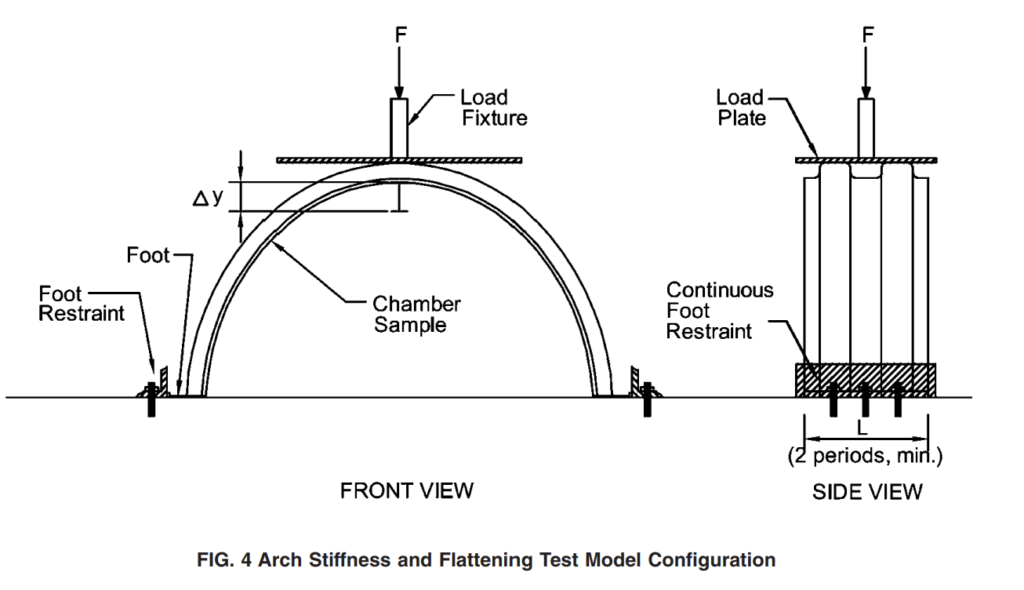
The Arch Stiffness Constant (ASC) evaluates the short-term structural stiffness of the chamber arch.
Testing is based on: ASTM D2412
with specific modifications defined by ASTM F2418.
The specimen consists of a section of the actual chamber.
34. ASC Test Machine
The apparatus should be a calibrated compression testing machine capable of:
- Constant crosshead movement
- Measuring vertical load
- Measuring vertical displacement
- Supporting large chamber specimens
- Using a rigid top loading plate
The test setup consists of:
- Lower rigid base
- Chamber specimen
- Foot restraints
- Upper load plate
- Load fixture
- Load cell
- Displacement measurement system
35. ASC Specimen Length
The specimen must contain at least: 2 complete corrugation periods
The specimen ends must be: Squarely cut
An irregular or angled cut can cause nonuniform loading and should not be accepted.
36. Selection of Worst-Case ASC Specimen
If chamber stiffness varies because of:
- Perforations
- Inspection ports
- Geometry changes
- Wall profile variations
the test specimen must represent the:
Lowest chamber stiffness condition
This is an important worst-case qualification requirement.
A manufacturer should not select only the structurally strongest chamber region for ASC testing.
37. Chamber Foot Restraint
During ASC testing, the outer edge of each chamber foot is restrained against: Lateral movement
However, the foot must remain: Free to rotate
This boundary condition is important because excessive clamping can artificially increase measured stiffness.
The fixture must therefore prevent horizontal translation without rigidly fixing foot rotation.
38. ASC Crosshead Speed
Crosshead motion must be constant at:
2.0 ± 0.2% of average chamber rise per minute
This speed is calculated individually from chamber rise.
Example
For chamber rise: 678 mm
Nominal speed: 0.02 × 678 = 13.56 mm/min
Permissible range:
1.8 to 2.2% of rise/min
approximately: 12.2 to 14.9 mm/min
Therefore the test machine must allow programmable crosshead speed.
39. ASC Measurement Point
The compression test continues until: 2% vertical deflection
of chamber rise is reached.
The corresponding plate load is recorded.
If: R = original rise
then: ΔR₂% = 0.02 × R
Example
Original rise: 678 mm
2% deflection: 13.56 mm
The load at this displacement is used to calculate ASC.
40. ASC Formula
The Arch Stiffness Constant is calculated from:
ASC = F / (Δy × L)
where:
- F = plate load at 2% vertical deflection
- Δy = percentage deflection = 2
- L = specimen length
In the original ASTM formulation, ASC is expressed as: lb/ft/% deflection
ASC should not be confused with conventional pipe stiffness.
41. Minimum ASC Requirements
ASTM F2418 specifies different minimum ASC values depending upon chamber classification.
16 × 33
Minimum ASC:
300 lb/ft/%
30 × 51
Minimum ASC:
300 lb/ft/%
45 × 76
Minimum ASC:
250 lb/ft/%
60 × 101
Minimum ASC: 250 lb/ft/%
Therefore: Measured ASC ≥ Applicable Table 1 Minimum → PASS
42. Flattening Test
The flattening test is performed immediately following the ASC test.
After recording the load at: 2% deflection
loading continues at the: Same crosshead speed
until vertical deflection reaches: 7% of the original rise
43. Flattening Test Displacement
Required displacement:
ΔR₇% = 0.07 × Original Rise
Example
For a chamber with rise: 678 mm
7% deflection: 47.46 mm
The chamber is then visually inspected.
44. Flattening Acceptance Criteria
During the test, the chamber must demonstrate no loss of load-carrying capacity. At 7% deflection, examination under:
- Normal light
- Unaided eye
must show no:
- Splitting
- Cracking
- Breaking
Therefore the chamber passes when:
No splitting + No cracking + No breaking + No loss of load-carrying capacity
are observed.
Any of these conditions constitutes failure.
45. Why ASC and Flattening Are Separate Evaluations
The two evaluations assess different behaviours.
ASC
Measures stiffness at relatively small deformation: 2% vertical deflection
Flattening
Assesses structural integrity at a larger deformation: 7% vertical deflection
A chamber can therefore possess sufficient initial stiffness but still fail the flattening requirement through:
- Local buckling
- Cracking
- Splitting
- Structural instability
Both requirements must be satisfied.
46. Accelerated Weathering Test
Material specimens representative of finished chambers must undergo accelerated weathering.
The test is conducted according to: ASTM D4329 – Cycle A
Minimum exposure time: 500 hours
After weathering, the material must continue to satisfy all material requirements specified by ASTM F2418.
47. Accelerated Weathering Equipment
Suitable equipment consists of a fluorescent UV weathering chamber capable of controlling the conditions required by ASTM D4329.
Typical equipment includes:
- Fluorescent UV lamps
- Temperature control
- Condensation or moisture system
- Exposure timer
- Specimen racks
- Irradiance monitoring where applicable
After the required exposure, specimens are retested for the relevant material properties.
48. Acceptance After Weathering
Weathered specimens must continue to meet the applicable material requirements.
This means accelerated UV exposure must not reduce the relevant properties below their minimum limits.
The chamber material cannot be accepted solely because it passed the tests before weathering.
49. Structural Design Requirement
Physical laboratory testing alone does not constitute complete chamber qualification.
The chamber must also be structurally designed according to: ASTM F2787
Structural design considers factors such as:
- Earth loads
- Vehicle loads
- Chamber geometry
- Soil-structure interaction
- Long-term material modulus
- Long-term strain capacity
- Cover depth
- Installation configuration
50. Minimum and Maximum Cover
The manufacturer must provide the purchaser with:
- Minimum allowable cover height
- Maximum allowable cover height
for:
- Traffic conditions
- Non-traffic conditions
These values must be based upon the structural requirements of ASTM F2787.
51. Full-Scale Installation Qualification
The manufacturer’s installation assumptions and structural design basis must be verified using representative full-scale chamber testing.
Testing must consider:
- Design earth load
- Design live load
- Representative chamber geometry
- Representative installation configuration
This ensures that analytical design assumptions correspond reasonably with actual chamber behaviour.
52. Sampling Requirements
Sampling is normally established by agreement between:
- Purchaser
- Manufacturer
Unless otherwise specified: Minimum 5 randomly selected chamber samples
must be tested.
Random selection is important to avoid intentionally selecting unusually strong or dimensionally ideal units.
53. Sample Acceptance
A chamber sample submitted for testing should represent the production lot and satisfy identification and traceability requirements.
The following should be recorded:
- Manufacturer
- Product name
- Chamber classification
- Material classification
- Lot number
- Production code
- Manufacturing date
- Mould or cavity where applicable
- Sample selection date
- Sampling personnel
54. Retesting Procedure
ASTM F2418 contains a clear procedure for failed tests.
If any test result does not satisfy the specification:
the test is repeated using samples from the same lot.
During retesting:
- Minimum requirements must not be reduced.
- Test limits must not be changed.
- The specified test method must not be replaced.
- The test procedure must not be modified merely to obtain a passing result.
55. Rejection after Retest
If failure occurs again during retesting:
The quantity of product represented by that test does not comply with ASTM F2418.
Therefore:
Initial Failure → Retest Same Lot
Retest Pass → Evaluate according to applicable acceptance procedure
Retest Failure → Lot represented by test is NON-COMPLIANT
This is an important product acceptance requirement.
56. Certification
When required by the purchase order or contract, the manufacturer must provide certification that the material and chamber were:
- Designed
- Manufactured
- Sampled
- Tested
- Inspected
according to ASTM F2418. When requested, the manufacturer must also provide the test results.
Certification should be signed by an authorized representative.
57. Required Product Marking
Compliant chambers must be marked with: ASTM Identification
The letters: ASTM
followed by the specification designation.
Material Identification
PP
followed by the applicable material classification.
Product Identification
Product name identifying the specific chamber geometry.
Manufacturer Identification
Manufacturer name or trademark.
Production Code
A production code allowing identification of:
- Manufacturing location
- Manufacturing date
Traceable marking is essential for quality control and lot identification.
58. Recommended Complete Test Equipment Package
A laboratory intended to perform comprehensive ASTM F2418 qualification should have access to the following equipment.
Universal Testing Machine
For:
- Tensile testing
- Flexural testing
- Arch stiffness
- Flattening
Required characteristics should include:
- Calibrated load cell
- Programmable crosshead speed
- Large compression test space
- Data acquisition
- Displacement measurement
Large Chamber Compression Fixture
Including:
- Rigid upper load plate
- Lower support platform
- Continuous foot restraints
- Adjustable chamber positioning
- Load introduction fixture
The restraint system must prevent lateral foot movement while allowing rotation.
Tensile Creep Testing System
For ASTM D2990:
- Multiple independent stations
- Constant load application
- Long-term temperature stability
- Automatic failure detection
- Displacement measurement
- Long-duration data acquisition
Tensile Testing Grips
Suitable for polypropylene tensile specimens and ASTM D638.
Flexural Test Fixture
Three-point flexural fixture suitable for ASTM D790.
Izod Impact Tester
Including:
- Appropriate pendulum
- Specimen fixture
- Notching machine
- Energy measurement system
UV Weathering Chamber
Suitable for ASTM D4329 Cycle A testing.
Precision Dimensional Instruments
Including:
- Micrometers
- Calipers
- Height gauges
- Ultrasonic thickness gauge
- Straight edges
- Measuring tape
- Flat reference table
59. Recommended Laboratory Test Sequence
A comprehensive product qualification can be organized in the following order:
Product Identification
↓
Visual Inspection
↓
Dimensional Inspection
↓
Wall Thickness
↓
Foot Width
↓
Rise
↓
Span
↓
Straightness
↓
Material Tensile Test
↓
Flexural Modulus
↓
Izod Impact
↓
Creep Rupture
↓
Creep Modulus
↓
Arch Stiffness Test
↓
Flattening Test
↓
Accelerated Weathering
↓
Post-Weathering Material Verification
↓
Structural Design Verification
↓
Full-Scale Installation Qualification
↓
Final Compliance Review
60. Principal Acceptance Criteria Summary
| Property | ASTM F2418 Requirement |
|---|---|
| Polypropylene content | ≥ 95% |
| PP classification | PP0330B99945 |
| Tensile yield stress | ≥ 21 MPa |
| Flexural modulus | ≥ 1000 MPa |
| Izod impact at 23 °C | ≥ 215 J/m |
| Conditioning temperature | 23 ± 2 °C |
| Conditioning RH | 50 ± 5% |
| Conditioning time | ≥ 4 h |
| Straightness | ≤ L/100 |
| 50-year creep rupture strength | ≥ 4.8 MPa |
| 50-year creep modulus | ≥ 165 MPa |
| Conventional creep test duration | 10,000 h |
| Creep modulus stress levels | Minimum 5 |
| ASC deflection | 2% of rise |
| ASC crosshead speed | 2.0 ± 0.2% rise/min |
| Minimum ASC, smaller classes | 300 lb/ft/% |
| Minimum ASC, larger classes | 250 lb/ft/% |
| Flattening deflection | 7% of rise |
| Flattening visual acceptance | No splitting, cracking or breaking |
| Flattening structural acceptance | No loss of load capacity |
| UV exposure | ≥ 500 h |
| Default random chamber samples | ≥ 5 |
61. Example ASC Calculation
Assume:
Plate load at 2% deflection: F = 1800 lb
Specimen length: L = 3 ft
Deflection: Δy = 2%
Then:
ASC = 1800 / (2 × 3)
ASC = 300 lb/ft/%
If the applicable classification requires: Minimum ASC = 300 lb/ft/%
then: Result = 300 → PASS
If the result were: 285 lb/ft/%
the chamber would fail a 300 lb/ft/% minimum requirement.
62. Example Straightness Calculation
Chamber length: L = 2400 mm
Maximum allowable deviation: L / 100
Therefore: 2400 / 100 = 24 mm
If measured deviation is: 18 mm → PASS
If measured deviation is: 29 mm → FAIL
63. Example Flattening Calculation
Original chamber rise: 1041 mm
Required 7% flattening displacement: 1041 × 0.07 = 72.87 mm
Therefore the test continues until the chamber has been vertically deflected by approximately: 72.9 mm
At this point the specimen is visually inspected. The chamber passes only if it shows no splitting, cracking or breaking and has not lost load-carrying capacity.
64. Critical Sources of Testing Error
Several errors can significantly influence ASTM F2418 results.
Incorrect Foot Restraint
Over-clamping may artificially increase chamber stiffness.
Wrong Crosshead Speed
ASC and flattening results depend upon controlled loading rate.
Testing a Non-Worst-Case Specimen
A specimen containing no opening or weak geometry may overestimate actual product stiffness.
Incorrect Rise Reference
The correct inside crown valley geometry must be used.
Unlevel Test Surface
Can distort rise, span and straightness measurements.
Insufficient Conditioning
Mechanical properties can vary if specimens are not temperature-conditioned.
Inadequate Load Calibration
Especially important for structural compression and creep equipment.
Temperature Instability During Creep
Polypropylene creep is highly temperature-sensitive.
Incomplete Wall Thickness Mapping
A few isolated measurements cannot substitute for the prescribed multi-location profile survey.
65. Recommended Test Report
A complete technical report should include:
- ASTM designation and revision
- Manufacturer
- Product model
- Chamber classification
- PP classification
- Production lot
- Production date
- Sample identification
- Visual inspection result
- Wall-thickness readings
- Minimum wall thickness
- Average wall thickness
- Foot-width measurements
- Rise measurements
- Span measurements
- Straightness results
- Tensile yield strength
- Flexural modulus
- Izod impact strength
- Creep test conditions
- Creep rupture regression
- 50-year creep rupture strength
- 50-year creep modulus
- ASC test specimen length
- Original rise
- Crosshead speed
- Load at 2% deflection
- Calculated ASC
- Load-deflection curve
- Flattening result at 7%
- Visual condition after flattening
- Weathering duration
- Post-weathering test results
- Applicable specification limit for each property
- Pass/Fail status
- Instrument identification
- Calibration status
- Test date
- Operator
- Authorized reviewer
66. Final Product Acceptance
Compliance with ASTM F2418 requires more than passing a single mechanical test.
A compliant polypropylene stormwater chamber must satisfy the complete applicable combination of:
- Material requirements
- Visual workmanship requirements
- Dimensional tolerances
- Minimum wall thickness
- Foot width
- Rise
- Span
- Straightness
- Long-term creep rupture strength
- Long-term creep modulus
- Arch stiffness
- Flattening resistance
- Weathering requirements
- Structural design requirements
- Installation qualification
- Sampling and inspection requirements
- Marking requirements
Therefore, product acceptance should be based upon a documented compliance matrix rather than one isolated test result.
Conclusion
ASTM F2418 provides a comprehensive qualification framework for polypropylene corrugated-wall underground stormwater chambers.
The specification combines material characterization with dimensional inspection, long-term creep testing and large-scale structural chamber testing.
One of the most important laboratory evaluations is the Arch Stiffness Constant test, in which a minimum two-period chamber specimen is compressed at a controlled speed equal to 2.0 ± 0.2% of chamber rise per minute.
The load required to generate 2% vertical deflection is used to calculate ASC.
Loading then continues to: 7% vertical deflection
for the flattening test.
At this deformation, the chamber must show:
- No splitting
- No cracking
- No breaking
- No loss of load-carrying capacity
Long-term PP performance is verified by creep testing at 23 °C. The minimum predicted 50-year creep rupture tensile strength is: 4.8 MPa
and the minimum 50-year tensile creep modulus is: 165 MPa.
The chamber material must additionally demonstrate minimum:
21 MPa tensile yield stress
1000 MPa flexural modulus
and: 215 J/m Izod impact resistance at 23 °C.
A minimum of five randomly selected chambers is specified unless purchaser and manufacturer agree otherwise.
When an initial test fails, ASTM F2418 requires retesting using material from the same lot without changing test methods or lowering specification limits. If the product fails again during retesting, the quantity of product represented by the test is considered non-compliant.
For reliable ASTM F2418 evaluation, the laboratory therefore requires not only a large structural compression tester, but also accurate dimensional inspection equipment, material testing equipment, long-term creep equipment, UV weathering equipment, and a controlled quality and traceability system.
