
Introduction
The CSA B184 Series:22 – Polymeric Subsurface Stormwater Management Structures establishes material, structural, dimensional, mechanical, long-term performance, testing, and quality-control requirements for polymeric structures used in subsurface stormwater management systems.
The standard is particularly applicable to stormwater chambers manufactured from:
- Polyethylene (PE)
- Polypropylene (PP)
The standard is divided into several parts:
- CSA B184.0:22 – General requirements and methods of testing for polymeric subsurface stormwater management structures
- CSA B184.1:22 – Polyethylene (PE) chambers
- CSA B184.2:22 – Polypropylene (PP) chambers
A major aspect of this standard is the verification of the long-term mechanical performance of polymeric chambers. Because these products may remain underground under sustained soil and traffic loads for several decades, short-term mechanical strength alone is not sufficient for evaluating their performance.
Therefore, CSA B184 includes evaluation of properties such as:
- Tensile creep rupture strength
- Tensile creep modulus
- Structural capacity
- Wall compression capacity
- Arch stiffness
- Flattening resistance
- Material properties
- Slow crack growth resistance for PE
- Oxidation induction time (OIT)
- Dimensional properties
Long-term creep testing is particularly important because thermoplastic materials exhibit viscoelastic behaviour, meaning that deformation can continue to increase even when the applied stress remains constant.
1. Applicable Standards
Several ASTM standards are referenced by CSA B184 for material characterization and mechanical testing.
ASTM D2990
Standard Test Methods for Tensile, Compressive, and Flexural Creep and Creep-Rupture of Plastics. This is the principal standard used for conventional tensile creep and creep-rupture testing.
ASTM D6992
Standard Test Method for Accelerated Tensile Creep and Creep-Rupture of Geosynthetic Materials Based on Time-Temperature Superposition Using the Stepped Isothermal Method. CSA B184 permits this method as an alternative for accelerated determination of long-term creep properties.
ASTM D3350
Standard Specification for Polyethylene Plastics Pipe and Fittings Materials. Used for classification of PE compounds.
ASTM D4101
Standard Specification for Polypropylene Injection and Extrusion Materials. Used for classification and evaluation of polypropylene compounds.
ASTM D638
Standard Test Method for Tensile Properties of Plastics.
ASTM D790
Standard Test Methods for Flexural Properties of Unreinforced and Reinforced Plastics and Electrical Insulating Materials.
ASTM D3895
Standard Test Method for Oxidative-Induction Time of Polyolefins by Differential Scanning Calorimetry.
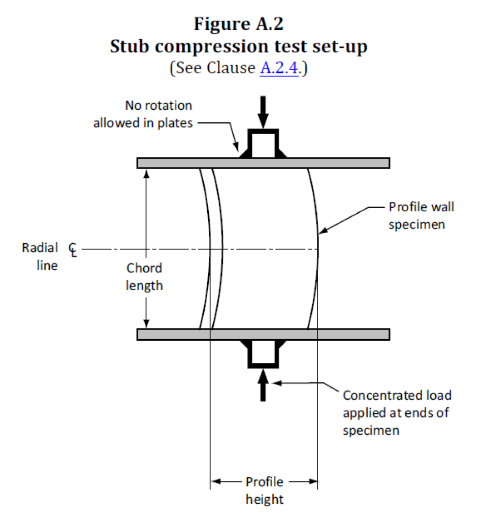
ASTM F2136
Standard Test Method for Notched, Constant Ligament-Stress (NCLS) Test to Determine Slow-Crack-Growth Resistance of HDPE Materials.
ASTM D4703
Standard Practice for Compression Molding Thermoplastic Materials into Test Specimens, Plaques, or Sheets.
ASTM D695
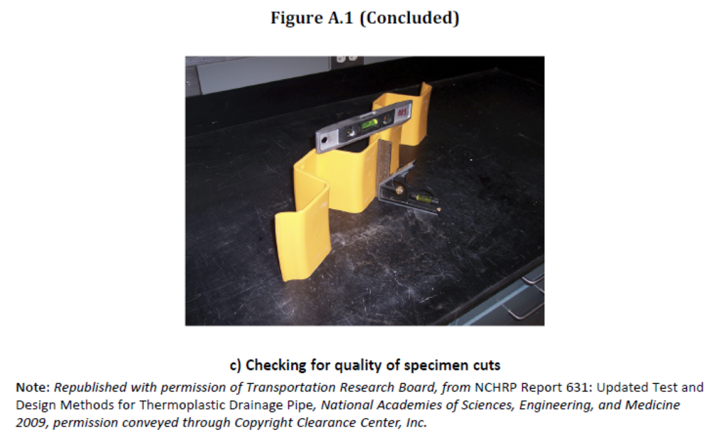
Standard Test Method for Compressive Properties of Rigid Plastics. The CSA B184 stub-compression test requires a compression testing machine complying with specified ASTM D695 requirements.
2. Why Creep Testing Is Important for Stormwater Chambers
A buried polymeric stormwater chamber is subjected to sustained loads generated by:
- Soil cover
- Pavement
- Static surcharge
- Vehicle loads
- Installation conditions
- Lateral soil pressure
- Long-term environmental exposure
Thermoplastic materials do not behave as perfectly elastic materials.
Under constant stress: Stress = Constant
but strain may progressively increase with time: ε = f(t)
This time-dependent deformation is known as creep.
As a result, a chamber that successfully passes a short-term mechanical test can still experience excessive deformation or eventual rupture after prolonged loading. CSA B184 therefore evaluates both:
Tensile Creep Modulus
The ability of the polymer to resist time-dependent deformation under a sustained tensile load.
Tensile Creep Rupture Strength
The long-term stress level that the material can sustain before creep rupture is predicted to occur.
3. Test Specimens
An important requirement of CSA B184 is that creep testing must represent the actual manufactured product. For both PE and PP chambers, tensile specimens used for creep testing are taken from the actual chamber. This is important because the manufacturing process can influence:
- Molecular orientation
- Residual stress
- Wall thickness
- Cooling history
- Crystallinity
- Moulding characteristics
- Material degradation
- Mechanical properties
Testing specimens directly removed from the final chamber therefore provides a more representative assessment of actual product performance than testing virgin resin alone.
4. Specimen Preparation
Representative sections are removed from the finished chamber. Tensile specimens are then prepared from these sections in accordance with the applicable specimen geometry and ASTM D2990 requirements.
Care should be taken during machining and cutting so that sample preparation does not introduce:
- Excessive heating
- Deep machining marks
- Scratches
- Cracks
- Local thinning
- Edge damage
- Residual deformation
- Stress concentrations
The gauge section should have a smooth and uniform surface. The specimen width and thickness must be accurately measured before testing. The initial cross-sectional area is calculated as:
A₀ = b × h
where:
- A₀ = initial cross-sectional area
- b = specimen width
- h = specimen thickness
Accurate measurement of the specimen cross-section is important because the applied tensile stress is calculated directly from this area.
5. Equipment Required for Tensile Creep Testing
A complete tensile creep testing system suitable for CSA B184 and ASTM D2990 should include the following components.
5.1 Constant-Load Loading System
The equipment must be capable of maintaining a controlled tensile load on the specimen for prolonged periods. Loading may be generated using:
- Dead weights
- Lever-arm loading systems
- Mechanical loading systems
- Servo-controlled loading systems
- Other suitable constant-load mechanisms
For long-duration testing, stability of the applied force is extremely important.
5.2 Multiple Independent Test Stations
CSA B184 creep-rupture testing requires specimens to be tested at a minimum of five different stress levels. For this reason, a practical creep testing machine should have several independent testing stations.
Each station should allow independent monitoring of:
- Applied load
- Applied stress
- Elongation
- Test time
- Test temperature
- Specimen status
- Rupture time
Laboratory systems with 5, 10, 20 or more independent stations can significantly increase testing efficiency.
5.3 Specimen Grips
The specimen grips must hold the tensile specimen securely throughout the entire duration of the test. The gripping arrangement should:
- Prevent specimen slipping
- Maintain axial alignment
- Minimize bending
- Prevent premature grip failure
- Avoid excessive local stress concentrations
- Prevent damage to the gauge section
Misalignment is particularly important in creep testing because even a small bending component can significantly influence long-term results.
5.4 Extension and Strain Measurement System
For creep modulus determination, deformation must be measured as a function of time. Suitable measurement devices may include:
- LVDT displacement transducers
- High-resolution digital displacement sensors
- Extensometers
- Dial indicators
- Non-contact displacement systems
The measurement system should provide sufficient resolution and long-term stability for monitoring relatively small dimensional changes over extended periods.
5.5 Temperature-Controlled Environment
Temperature has a major influence on polymer creep behavior. CSA B184 specifies a creep test temperature of: 23 °C
for both tensile creep rupture and tensile creep modulus testing.
The creep testing equipment should therefore preferably be installed in:
- A temperature-controlled laboratory
- An environmental chamber
- A conditioned enclosure
Continuous monitoring and recording of test temperature is recommended during long-duration testing.
5.6 Data Acquisition System
An automatic data acquisition system is highly recommended for long-term testing. The software should be capable of recording:
- Specimen identification
- Applied force
- Applied stress
- Displacement
- Strain
- Temperature
- Elapsed time
- Failure time
- Test status
Because creep tests may continue for thousands of hours, automatic data recording substantially improves repeatability and reduces operator-dependent errors.
6. Tensile Creep Rupture Test
The tensile creep rupture test is one of the principal long-term qualification tests required by CSA B184. For PE and PP chambers, the test is conducted according to: ASTM D2990 at: 23 °C
The objective is to establish the relationship between: Applied Tensile Stress and Time to Rupture
The experimental data are then used to determine the predicted 50-year tensile creep rupture strength.
7. Number of Stress Levels
CSA B184 requires a minimum of: 5 Stress Levels
The stress levels must be selected so that specimen failures occur at relatively regular intervals on a logarithmic time scale.
Experimental failure data are generated up to: 10,000 hours
which is approximately: 417 days
This is a critical consideration when selecting the testing equipment because the system must be capable of reliable and continuous operation for more than one year.
8. Calculation of Applied Stress
The applied tensile stress is calculated using:
σ = F / A₀
where:
- σ = tensile stress
- F = applied tensile force
- A₀ = original specimen cross-sectional area
The required load can therefore be calculated from:
F = σ × A₀
Example
Assume:
Specimen width: 10 mm
Specimen thickness: 4 mm
Cross-sectional area: A₀ = 10 × 4 = 40 mm²
Required stress: 5 MPa
Since: 1 MPa = 1 N/mm²
the required force is:
F = 5 × 40
F = 200 N
If the load is applied using dead weights: m = F / g
Therefore:
m = 200 / 9.81
m ≈ 20.4 kg
If a lever-arm creep tester is used, the lever ratio must be taken into account when calculating the actual dead weight.
9. Tensile Creep-Rupture Test Procedure
A typical test procedure consists of the following steps:
- Identify each specimen.
- Record the chamber model and manufacturing batch.
- Record the location from which the specimen was removed.
- Measure specimen width.
- Measure specimen thickness.
- Calculate initial cross-sectional area.
- Determine the target test stress.
- Calculate the required tensile force.
- Install the specimen in the grips.
- Check specimen alignment.
- Stabilize the specimen at the required temperature.
- Apply the calculated tensile load.
- Start the test timer.
- Maintain the specimen at 23 °C.
- Continuously or periodically monitor the specimen.
- Record the exact time at rupture.
- Record the failure mode.
- Repeat the procedure for all specified stress levels.
The resulting dataset consists primarily of: Applied Stress – Time to Failure pairs.
10. Creep-Rupture Regression Analysis
The experimental data are evaluated using logarithmic regression. The relationship between stress and failure time is analyzed to determine long-term material behavior.
Conceptually, the results are represented as: Applied Stress vs. Log (Time to Failure)
The regression curve is then extrapolated to the required long-term period.
CSA B184 specifies evaluation of a: 50-Year Creep Rupture Strength
A period of 50 years is approximately: 438,000 hours
The laboratory therefore does not physically perform a 50-year test.
Instead, experimental creep data extending up to 10,000 hours are used to establish a statistically valid regression relationship from which the 50-year value is predicted.
11. Acceptance Criterion for PE Creep Rupture Strength
For polyethylene chambers, the predicted 50-year tensile creep rupture strength should normally be at least: 4.8 MPa
or: 700 psi
Therefore: 50-Year Tensile Creep Rupture Strength ≥ 4.8 MPa = PASS
A lower value may still be acceptable for PE if the applicable chamber structural design requirements are satisfied.
This exception should be carefully evaluated in the context of the complete structural design rather than treated as an automatic acceptance.
12. Acceptance Criterion for PP Creep Rupture Strength
For polypropylene chambers: 50-Year Tensile Creep Rupture Strength ≥ 4.8 MPa
or: ≥ 700 psi
Therefore: Result ≥ 4.8 MPa = PASS
13. Tensile Creep Modulus Test
The second major long-term mechanical test is the determination of tensile creep modulus.
Unlike creep-rupture testing, the objective is not primarily to determine the failure time.
Instead, the deformation of the specimen is monitored while a constant tensile stress is maintained.
The test is conducted according to ASTM D2990 at: 23 °C
The applied stress must be: 3.5 MPa
or: the design service stress
whichever is higher.
Therefore: Test Stress = Maximum of 3.5 MPa or Design Service Stress
This requirement is important because the test stress should not automatically be assumed to be 3.5 MPa when the actual chamber design stress is higher.
14. Measurement of Creep Strain
Let: L₀ = Initial gauge length
and: ΔL(t) = Elongation measured at time t
The creep strain is calculated as: ε(t) = ΔL(t) / L₀
If strain is expressed as a percentage: ε(t)% = [ΔL(t) / L₀] × 100
The deformation should be recorded at suitable time intervals to establish a reliable strain-versus-time curve.
15. Calculation of Tensile Creep Modulus
The tensile creep modulus at time t is determined using: E꜀(t) = σ / ε(t)
where:
- E꜀(t) = creep modulus at time t
- σ = constant applied tensile stress
- ε(t) = measured creep strain
Because creep strain generally increases with time, the apparent creep modulus of the polymer generally decreases as the loading period increases.
16. 50-Year Creep Modulus
The measured creep data are analyzed using a suitable logarithmic regression relationship.
The curve is extrapolated to determine the predicted tensile creep modulus at: 50 years
or approximately: 438,000 hours
The resulting value represents the long-term stiffness of the material under sustained loading.
17. Acceptance Criterion for PE Creep Modulus
For PE chambers, the required 50-year tensile creep modulus is: ≥ 138 MPa
or: ≥ 20,000 psi
Therefore: E₅₀ ≥ 138 MPa = PASS
18. Acceptance Criterion for PP Creep Modulus
For PP chambers, the 50-year tensile creep modulus must be: ≥ 165 MPa
or: ≥ 24,000 psi
Therefore: E₅₀ ≥ 165 MPa = PASS
19. Accelerated Creep Testing According to ASTM D6992
CSA B184 permits an accelerated alternative to the conventional long-duration ASTM D2990 method.
The Time-Temperature Superposition Method described in ASTM D6992 may be used for determining:
- Tensile creep rupture strength
- Tensile creep modulus
The principle is based on the temperature dependence of polymer viscoelastic behaviour.
At elevated temperatures, molecular relaxation and creep occur more rapidly.
By performing tests at several controlled temperatures and mathematically shifting the resulting curves along the logarithmic time axis, a long-term: Master Curve
can be generated.
This technique can considerably reduce the calendar time required to characterize long-term polymer behaviour.
20. PE Slow Crack Growth Resistance
Polyethylene chambers have an additional long-term durability requirement related to: Slow Crack Growth Resistance
The PE compound is evaluated using the: NCLS – Notched Constant Ligament Stress Test
The chamber material is ground and a test plaque is prepared according to ASTM D4703 Procedure C.
The specified cooling rate is: 15 °C/min
The average failure time of the test specimens prepared from these plaques must normally be: ≥ 100 hours
Alternative combinations of test stress and time-to-failure may be used when justified by chamber design stresses and service-life objectives.
21. NCLS Test on Actual Chamber Specimens
CSA B184.1 also specifies NCLS testing according to ASTM F2136 with specific modifications.
The test is performed on: 5 tensile specimens
taken from the actual chamber.
The applied stress is: 1.72 MPa
or: 230 psi
This test evaluates resistance of polyethylene to slow crack propagation under sustained mechanical loading.
22. Oxidation Induction Time Test for PE
Oxidative stability of polyethylene is evaluated using: OIT – Oxidation Induction Time
Test standard: ASTM D3895
Test temperature: 200 °C
Minimum OIT: 20 minutes
Therefore:
OIT ≥ 20 min = PASS
The specimen may be prepared from a moulded plaque produced according to ASTM D4703 Procedure C at a cooling rate of 15 °C/min.
Alternatively, specimens may be removed directly from the actual chamber.
23. Polyethylene Material Requirements
Virgin polyethylene compounds used for manufacturing chambers or accessories must comply with the required ASTM D3350 material classifications.
For thermoformed chambers: PE405400C or PE405400E
For injection-moulded chambers: PE516500C or PE516500E
Carbon black content must not exceed: 3%
The minimum amount of PE resin in the compound is: 95% by weight
24. Polypropylene Material Requirements
Virgin PP compounds used for manufacturing chambers or accessories must comply with: ASTM D4101 Cell Classification PP0330B99945
The minimum PP resin content is: 95% by weight
Additional tensile, flexural and oxidative-stability requirements also apply.
25. PP Tensile Yield Strength
The minimum tensile stress at yield for polypropylene is: 21 MPa
or approximately: 3000 psi
when measured according to: ASTM D638
Therefore: Tensile Stress at Yield ≥ 21 MPa = PASS
26. PP Flexural Modulus
The required 1% secant flexural modulus for PP is: ≥ 1000 MPa
or: ≥ 145,000 psi
determined according to: ASTM D790 Procedure A
Therefore: Flexural Modulus ≥ 1000 MPa = PASS
27. PP Oxidation Induction Time
For polypropylene:
Test standard: ASTM D3895
Test temperature: 200 °C
Minimum OIT: 25 minutes
Therefore: OIT ≥ 25 min = PASS
The PP OIT criterion is therefore higher than the 20-minute minimum specified for PE.
28. Conditioning of Test Specimens
Unless otherwise specified by CSA B184.1 or CSA B184.2, test specimens are conditioned before testing at: 23 ± 2 °C
and: 50 ± 5% Relative Humidity
for not less than: 4 hours
according to Procedure A of ASTM D618.
Proper conditioning is important because temperature and moisture conditions can influence dimensional and mechanical test results.
29. Chamber Wall Thickness Measurement
CSA B184 requires systematic wall-thickness measurement.
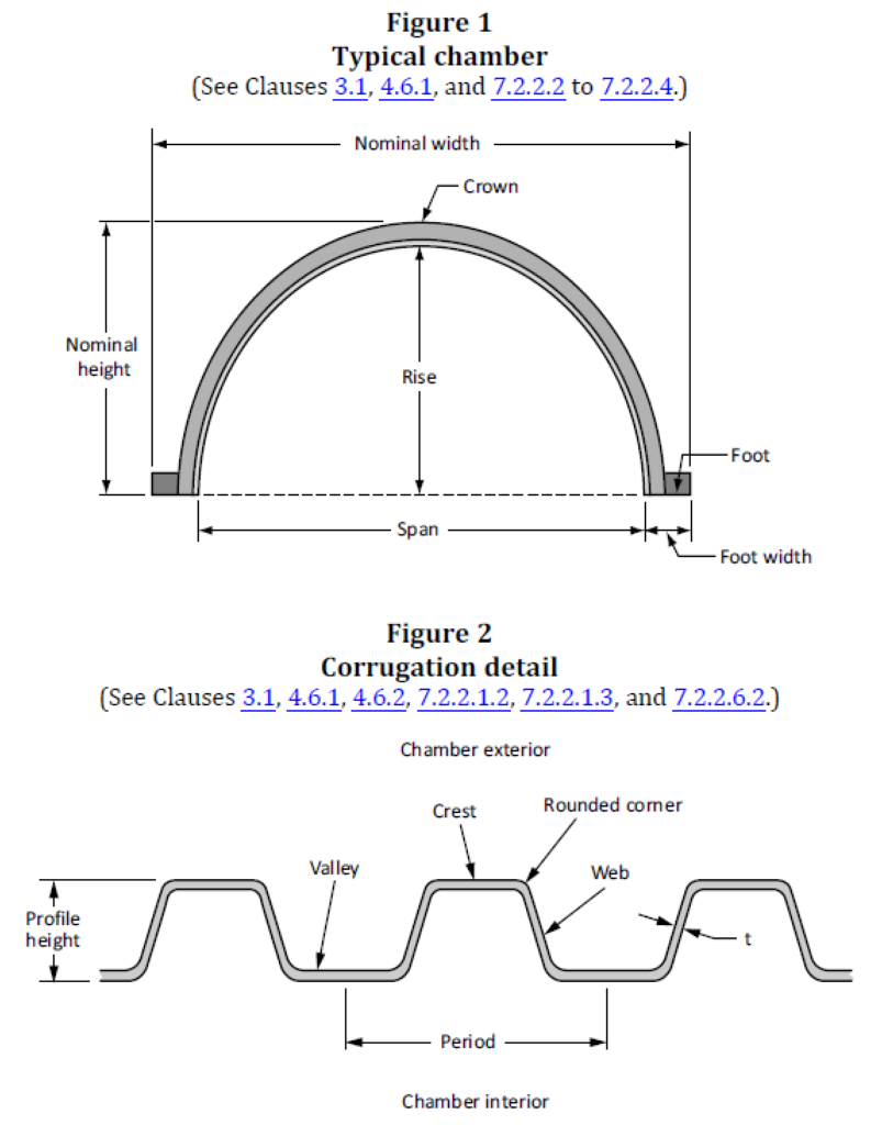
At least two sets of measurements are taken along the longitudinal axis of the chamber.
Each set includes at least:
8 measurement positions
evenly distributed around the chamber circumference.
The minimum and average wall thickness must be recorded.
30. Injection-Moulded Chamber Wall Thickness
For injection-moulded chambers, four measurements are taken across the corrugation profile at each circumferential measurement position.
These locations include:
- Valley
- Crest
- First web
- Second web
The resulting measurements are used to determine the minimum and average wall thickness.
31. Thermoformed Chamber Wall Thickness
For thermoformed chambers, eight measurements are taken across the corrugation profile at each circumferential location.
Measurements include:
- Valley
- Crest
- Webs
- Rounded corners
Voids produced by gas-assisted flow channels are excluded from the measured wall thickness.
32. Chamber Foot Width
The chamber foot width is measured at three positions on each foot:
- One end
- Mid-length
- Opposite end
The minimum and average foot width for each chamber foot must be recorded.
33. Chamber Rise Measurement
The chamber is placed on a: Flat and level surface
with no external load other than its own weight. The maximum vertical distance from the floor to the inner surface of the crown valley is measured. Measurements are made at:
- One end
- Mid-length
- Opposite end
The average of the three measurements is reported as chamber rise.
34. Chamber Span Measurement
The chamber is placed on a flat, level surface without external loading. The horizontal distance between the inside valley surfaces at the chamber feet is measured. Measurements are taken at:
- One end
- Mid-length
- Opposite end
The average of the three values is reported as chamber span.
35. Deviation from Straightness
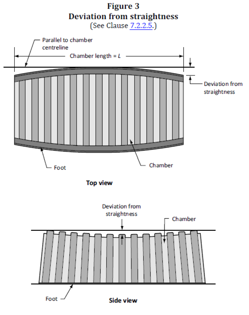
Deviation from straightness is evaluated with the chamber resting on a flat, level surface. Measurements are performed at:
- Chamber crown
- First foot
- Second foot
The maximum deviation from a straight reference line along the chamber length is recorded.
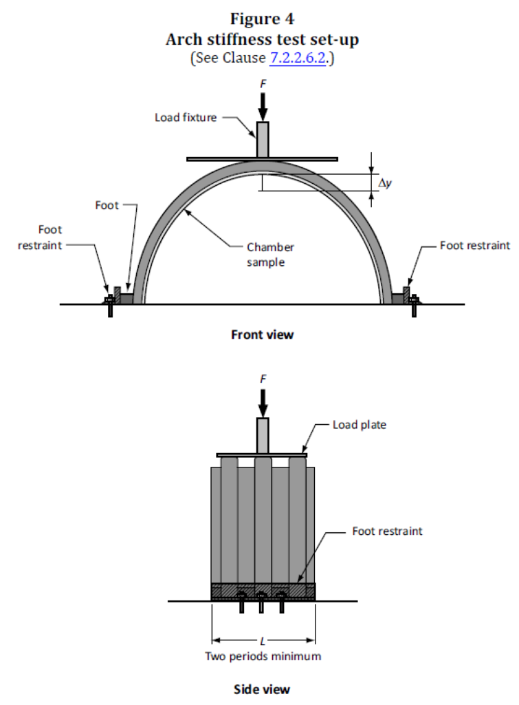
36. Arch Stiffness Constant – ASC
The chamber stiffness is evaluated using the: Arch Stiffness Constant – ASC
The specimen length must be at least: Two profile periods
A vertical compressive load is applied to the chamber.
The load required to produce: 2% vertical deflection
is determined.
ASC is calculated using:
ASC = F / (Δy × L)
where:
- F = plate load required to produce 2% vertical deflection
- Δy = deflection
- L = specimen length
Lower ASC values generally indicate greater sensitivity of the chamber to distortion during backfilling.
37. Flattening Test
After determination of ASC, loading continues at the same crosshead speed. The chamber is compressed until the vertical deflection reaches: 7% of the original rise
During loading, the applied force must not decrease before the 7% deflection level is reached.
After reaching 7% deflection, the specimen is visually inspected. The chamber fails the flattening test if:
- The load decreases before reaching 7% deflection
- Significant defects are observed
- Significant local buckling occurs
- Crimping or other damaging deformation is observed
The purpose of this test is to verify that the chamber can sustain significant installation-related deformation without unstable structural failure.
38. Chamber Wall Compression Capacity Test
CSA B184.0 contains a dedicated compression-capacity test for corrugated chamber wall sections. This test is different from the long-term ASTM D2990 creep test.
A wall section is compressed between: Two rigid parallel steel plates
at a controlled displacement rate. The applied force acts in the circumferential direction.
The following quantities are continuously monitored:
- Applied load
- Crosshead displacement
- Test time
The test continues until the load no longer increases as deformation increases. The maximum recorded force is defined as the: Ultimate Load
39. Compression Testing Machine Requirements
The compression machine must be a calibrated constant-rate-of-crosshead-movement testing machine.
Required crosshead speed: 1.27 ± 0.25 mm/min
or: 0.05 ± 0.01 in/min
Required force-measurement accuracy: ±110 N
or: ±25 lb
The machine must have sufficient load capacity to compress the specimen to failure or ultimate capacity.
40. Compression Loading Plates
The load must be applied through two parallel steel plates.
The plates must be:
- Flat
- Smooth
- Clean
- Sufficiently rigid to avoid bending
Minimum plate thickness: 6.0 mm
Plate length: Not less than the specimen longitudinal length
Plate width: Not less than profile height + 150 mm
41. Displacement Measurement for Compression Test
Crosshead displacement must be measured using a suitable displacement-measurement instrument.
Required measurement accuracy: 0.025 mm
or: 0.001 in
A sufficiently high-resolution LVDT, displacement transducer or calibrated machine encoder may therefore be required.
42. Stub Compression Test Specimen
The compression specimen must be removed directly from a finished chamber.
The required specimen dimensions include:
Longitudinal length: 3 profile periods
Circumferential chord length: 1.5 × Profile Height ± 6 mm
The specimen ends must be:
- Flat
- Parallel
- Square
- Properly aligned relative to the chamber radial direction
Accurate sample preparation is essential because uneven specimen ends can cause non-uniform load distribution.
43. Preparation of Stub Compression Specimens
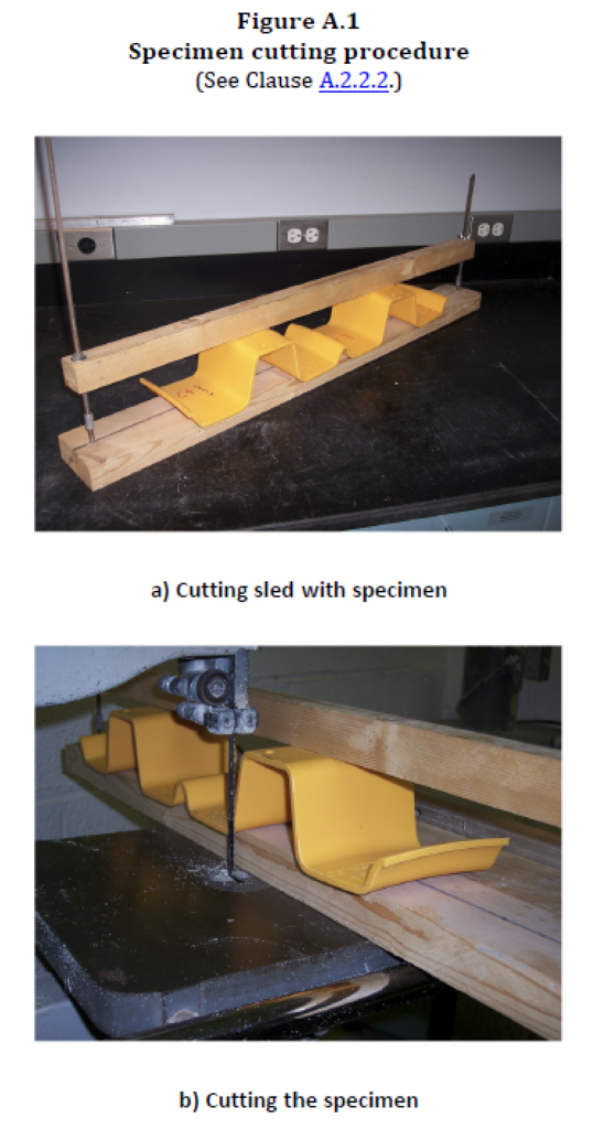
The specimen is first rough-cut approximately: 50 mm longer than the final required chord length
using a reciprocating saw. The longitudinal ends are then squared using:
- A band saw
- Or belt sander
A carpenter’s square is used to verify the cut geometry. The circumferential ends are then cut square and parallel. A cutting sled may be used with the band saw to maintain alignment.
The specimen should be clamped securely enough to prevent movement during cutting, but the clamping force must not flatten or distort the chamber profile. Repeated small cuts should be made from opposite ends until:
- Correct chord length is achieved
- Ends are parallel
- Ends are flat
- Ends are square
A flat reference surface and level can be used for final inspection.
Minor corrections may be made using a belt sander.
44. Conditioning for Stub Compression Testing
Before the compression capacity test, the specimen must be conditioned for at least: 4 hours
in air at: 23 ± 2 °C
The test must also be performed in a room maintained at the same temperature.
45. Stub Compression Test Procedure
The procedure includes the following steps:
- Record chamber span.
- Record chamber rise.
- Record chamber model or classification.
- Record chamber profile type.
- Record manufacturer.
- Record conditioning temperature.
- Record test date.
- Measure specimen longitudinal length.
- Measure specimen chord length.
- Measure specimen profile height.
- Position the specimen centrally on the lower loading plate.
- Align the specimen with the machine loading axis.
- Install the displacement indicator.
- Lower the upper plate into contact with the specimen.
- Apply no more than approximately 220 N seating force.
- Start compression at 1.27 ± 0.25 mm/min.
- Continuously record load.
- Continuously record displacement.
- Continuously record time.
- Record the ultimate load.
- Stop the test when the load fails to increase with increasing deflection.
46. Calculation of Compression Capacity
The ultimate compressive load capacity per unit longitudinal length of wall is calculated as:
Compression Capacity per Unit Length = Ultimate Load / Specimen Longitudinal Length
The result represents the compressive load-carrying capability of the profile wall.
CSA B184 requires three tests for chamber-wall compression capacity and the test results are averaged. Specimens should be taken from the portion of the chamber subjected to the highest compression stress in service.
This region is typically located just above the chamber foot.
47. Acceptance Criterion for Chamber Wall Compression Capacity
The measured compression capacity must be corrected to account for the change in elastic modulus between:
- Short-term laboratory conditions
- Long-term installed conditions
The corrected compression capacity must exceed the: Manufacturer’s Stated Design Capacity
Therefore: Corrected Compression Capacity > Design Compression Capacity = PASS
48. Full-Scale Structural Testing
CSA B184 also requires full-scale verification of the chamber under representative installation conditions.
Testing must consider:
- Minimum cover
- Maximum burial depth
- Earth loads
- Vehicle loads
- Sustained loads
- Applicable design load factors
- Resistance factors
The standard requires stormwater structures to be designed for a minimum service life of: 50 years
Structural verification therefore combines short-term test data, long-term material properties and structural analysis.
49. Minimum Cover Testing
The chamber must be tested under the manufacturer’s specified minimum cover conditions.
Full-scale testing may involve loading based on the: AASHTO Design Truck
with the applicable load and resistance factors.
The specimen temperature during the test must be at least: 10 °C
unless the results are corrected to account for the increased stiffness of the polymer at lower temperatures.
50. Maximum Burial Depth
Deep burial performance must also be verified. The chamber must demonstrate adequate structural capacity under the earth loads associated with the manufacturer’s stated maximum burial depth.
Long-term reduction in polymer modulus must be included when evaluating the structural resistance.
51. New Product Designs and Design Changes
Full-scale structural testing is required for new chamber designs.
Retesting is also required when significant changes are made, including situations where:
- Structural geometry changes sufficiently to modify failure modes
- Wall thickness is reduced by more than 10%
- Long-term modulus is reduced by more than 20%
- Long-term tensile strength is reduced by more than 20%
This requirement prevents manufacturers from applying qualification data from one product indiscriminately to substantially different designs.
52. PE Major Acceptance Requirements
For polyethylene chambers, important acceptance criteria include:
- PE resin content: minimum 95% by weight
- Carbon black content: maximum 3%
- 50-year tensile creep rupture strength: normally ≥ 4.8 MPa
- 50-year tensile creep modulus: ≥ 138 MPa
- OIT at 200 °C: ≥ 20 min
- NCLS average plaque-specimen failure time: normally ≥ 100 h
- Chamber dimensional requirements: according to applicable chamber classification
- Arch stiffness: according to chamber classification
- Flattening test: no load reduction up to 7% deflection and no injurious defects
- Compression capacity: corrected capacity must exceed design capacity
53. PP Major Acceptance Requirements
For polypropylene chambers, important acceptance criteria include:
- PP resin content: minimum 95% by weight
- Cell classification: PP0330B99945
- Tensile stress at yield: ≥ 21 MPa
- Flexural modulus, 1% secant: ≥ 1000 MPa
- OIT at 200 °C: ≥ 25 min
- 50-year creep rupture strength: ≥ 4.8 MPa
- 50-year creep modulus: ≥ 165 MPa
- Chamber dimensional requirements: according to applicable chamber classification
- Arch stiffness: according to chamber classification
- Flattening test requirements
- Chamber wall compression capacity requirements
54. Recommended Laboratory Equipment
A laboratory intending to perform a comprehensive CSA B184 qualification program should have access to the following equipment.
1. Multi-Station Tensile Creep Tester
For long-duration ASTM D2990 testing. Recommended features include:
- Multiple independent testing stations
- Dead-weight or controlled constant-load application
- Automatic failure detection
- Long-term load stability
- Independent specimen monitoring
2. Environmental or Temperature-Controlled Chamber
For maintaining stable test temperature.
3. Displacement Measurement System
Such as:
- LVDT
- High-resolution digital sensor
- Extensometer
4. Data Acquisition System
For automatic recording of:
- Time
- Load
- Displacement
- Strain
- Temperature
- Failure events
5. Universal Testing Machine
For:
- Tensile testing
- Flexural testing
- Chamber compression testing
- Stub compression testing
6. Compression Platens
Large rigid parallel steel plates suitable for chamber wall sections.
7. DSC – Differential Scanning Calorimeter
For OIT testing according to ASTM D3895.
8. NCLS Test Equipment
For slow crack growth evaluation according to ASTM F2136.
9. Specimen Preparation Equipment
Including:
- Band saw
- Reciprocating saw
- Belt sander
- Cutting fixture
- Cutting sled
- Flat reference table
- Carpenter’s square
- Precision caliper
- Micrometer
55. Qualification Testing vs Routine Quality Control
CSA B184 distinguishes between: Performance Qualification Testing
and: In-Plant Quality Control
Performance qualification testing is conducted initially for each relevant chamber design and compound.
Depending on the chamber material, qualification testing includes:
- Wall-section structural capacity
- Minimum-cover performance
- Maximum-cover performance
- Volume verification
- Arch stiffness
- Flattening
- Chamber-wall compression capacity
- Cell classification
- Material properties
- Creep
- OIT
- Slow crack growth for PE
Long-duration creep testing should therefore generally be considered a product/material qualification test rather than a routine test performed on every individual chamber.
56. Routine Production Quality Control
Routine quality-control inspections include monitoring of:
- Manufacturing process
- Visual quality
- Polymer material properties
- Critical dimensions
- Product weight
- Product markings
- Structural index properties
Visual inspection is conducted continuously. Critical dimensions and part weight should normally be checked:
- At the start of the shift
- Around the middle of the shift
- At the end of the shift
- Whenever a significant process change occurs
Markings are checked at the start of production and periodically thereafter.
57. Visual Acceptance Requirements
Finished stormwater chambers and accessories must be free from visible defects that could impair performance or structural integrity. Unacceptable defects include:
- Cracks
- Gouges
- Unintended holes
- Foreign inclusions
- Blisters
- Unintended voids
- Other injurious defects
The product should also be reasonably uniform in:
- Colour
- Opacity
- Density
- Other physical characteristics
58. Treatment of Non-Conforming Products
If a finished product fails to satisfy applicable requirements, production manufactured after the previous acceptable inspection should be re-inspected. The purpose is to determine which products manufactured during the intervening period are non-conforming. Finished products that fail to comply with the standard must be rejected.
This makes production traceability particularly important. The manufacturer should maintain records for:
- Material lot
- Production batch
- Machine or mould
- Processing conditions
- Inspection results
- Test results
- Operator
- Production date
59. Marking Requirements
Compliant chambers must be permanently and legibly marked with at least:
- Manufacturer name or trademark
- Product model or product name
- Polymer designation such as PE or PP
- Manufacturing process identification when applicable
- Date or manufacturing date code
- Applicable CSA standard designation
Manufacturing-process identification can include:
- SF – Structural Foam
- IM – Injection Moulding
- TF – Thermoforming
60. Test Report Requirements
A complete technical test report should include at least:
- Standard designation
- Standard revision
- Test method
- Chamber manufacturer
- Chamber model
- Product classification
- Polymer type
- Manufacturing batch
- Specimen identification
- Sampling location on chamber
- Specimen dimensions
- Specimen cross-sectional area
- Conditioning temperature
- Conditioning duration
- Test temperature
- Applied load
- Applied stress
- Gauge length
- Elongation
- Strain
- Time
- Rupture time
- Failure mode
- Number of specimens
- Regression equation
- Regression graph
- Extrapolated long-term value
- 50-year creep rupture strength
- 50-year creep modulus
- Applicable acceptance criterion
- Pass/Fail conclusion
- Test equipment identification
- Calibration status
- Laboratory identification
- Test operator
- Test date
For creep rupture testing, the report should include a graph showing: Stress vs. Time to Rupture
together with the calculated regression line and extrapolated long-term result.
61. Summary of Main Test Conditions
| Test | Requirement |
|---|---|
| Tensile creep rupture standard | ASTM D2990 |
| Creep rupture temperature | 23 °C |
| Minimum number of stress levels | 5 |
| Maximum experimental duration specified | Up to 10,000 h |
| Long-term prediction period | 50 years |
| PE 50-year creep rupture strength | ≥ 4.8 MPa normally |
| PP 50-year creep rupture strength | ≥ 4.8 MPa |
| Creep modulus test stress | 3.5 MPa or design service stress, whichever is higher |
| PE 50-year creep modulus | ≥ 138 MPa |
| PP 50-year creep modulus | ≥ 165 MPa |
| PE OIT | ≥ 20 min at 200 °C |
| PP OIT | ≥ 25 min at 200 °C |
| PE NCLS actual chamber specimens | 5 |
| NCLS applied stress | 1.72 MPa |
| PP tensile yield stress | ≥ 21 MPa |
| PP flexural modulus | ≥ 1000 MPa |
| Stub compression crosshead speed | 1.27 ± 0.25 mm/min |
| Stub compression load accuracy | ±110 N |
| Stub compression displacement accuracy | 0.025 mm |
| Compression plate minimum thickness | 6 mm |
| Stub specimen longitudinal length | 3 profile periods |
| Stub specimen chord length | 1.5 × profile height ± 6 mm |
| Stub specimen conditioning | Minimum 4 h at 23 ± 2 °C |
| Flattening deflection | 7% of original rise |
62. Interpretation of the 50-Year Values
An important technical point is that the predicted 50-year creep modulus and creep rupture strength should not be interpreted as an exact indication that the product will fail immediately after 50 years.
These values represent material properties determined from long-term regression analysis.
Actual service performance also depends on:
- Chamber geometry
- Structural design
- Profile geometry
- Wall thickness
- Soil properties
- Installation quality
- Cover depth
- Traffic loading
- Foundation
- Embedment
- Backfill
- Temperature
- Environmental conditions
- Structural safety factors
Therefore, creep testing represents one important component of the complete structural qualification process.
Conclusion
CSA B184 Series:22 provides a comprehensive framework for evaluating polymeric subsurface stormwater management chambers manufactured from polyethylene and polypropylene.
The standard combines:
- Material qualification
- Long-term creep testing
- Slow crack growth evaluation
- OIT testing
- Mechanical testing
- Dimensional inspection
- Chamber stiffness testing
- Flattening evaluation
- Profile-wall compression testing
- Full-scale structural testing
- Production quality control
For long-term performance, the most important tests are tensile creep rupture and tensile creep modulus according to ASTM D2990.
Creep rupture testing is performed at 23 °C using at least five stress levels selected to generate specimen failures over a logarithmic time scale extending up to approximately 10,000 hours.
The experimental data are then extrapolated to determine 50-year material properties.
For PE chambers, the principal long-term values are:
50-Year Tensile Creep Rupture Strength: normally ≥ 4.8 MPa
50-Year Tensile Creep Modulus: ≥ 138 MPa
For PP chambers:
50-Year Tensile Creep Rupture Strength: ≥ 4.8 MPa
50-Year Tensile Creep Modulus: ≥ 165 MPa
When these tests are combined with OIT, slow crack growth, dimensional inspection, arch stiffness, flattening, compression-capacity testing and full-scale structural verification, a comprehensive evaluation of the chamber’s suitability for long-term underground stormwater applications can be achieved.
