

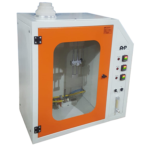
🔥 Fire Hazard Testing | 50 W Premixed Flame | Apparatus Requirements | Flame Confirmation | Test Arrangement
A standardized flame test is not defined only by flame height.
To obtain reproducible fire-test results, the burner geometry, methane purity, gas flow, air supply, flame characteristics, measurement system, test environment and—most importantly—the thermal performance of the flame must all comply with specified requirements.
IEC 60695-11-4:2011 defines the apparatus and confirmation method for producing a standardized 50 W nominal premixed test flame.
The standard covers:
- Burner construction and dimensions
- Gas supply system
- Methane requirements
- Gas flow and pressure measurement
- Flame adjustment and geometry
- Flame-height verification
- Copper calibration block
- Thermocouple requirements
- Temperature/time measurement
- Test chamber conditions
- Flame confirmation procedure
- Acceptance criteria
- Recommended flame application arrangements
1. PURPOSE AND SCOPE
IEC 60695-11-4 specifies the detailed requirements necessary to produce a: 50 W nominal premixed test flame
with an approximate overall flame height of: 20 mm
The standard also specifies a thermal confirmation procedure to verify that the produced flame actually delivers the required heating performance. This distinction is essential.
A flame that visually appears to be 20 mm high cannot automatically be considered a standardized 50 W flame. The complete burner system must first satisfy the construction and operating requirements and then pass the specified copper-block heating confirmation test.
2. STANDARDIZED 50 W FLAME — BASIC REQUIREMENTS
A standardized 50 W nominal test flame shall be: Burner
Produced using burner hardware conforming to the specified burner assembly and dimensional requirements.
Fuel is Methane Minimum purity: ≥ 98 %
Gas Flow: The methane supply shall provide a flow equivalent to: 105 ± 5 ml/min
at the reference conditions of: 23 °C and 0.1 MPa
Measurements made under actual operating conditions shall therefore be corrected to the specified reference conditions where necessary.
Flame Geometry
The flame shall be:
- stable;
- symmetrical;
- completely blue after correct adjustment.
Its overall height should normally be: 18 mm to 22 mm
with adjustment targeted toward: 20 mm
Thermal Confirmation
When tested using the specified copper-block confirmation arrangement, the time required to heat the copper block from: 100 ± 2 °C to: 700 ± 3 °C shall be: 44 ± 2 s
This thermal response is the principal confirmation that the standardized flame has been correctly established.
3. COMPLETE BURNER REQUIREMENTS
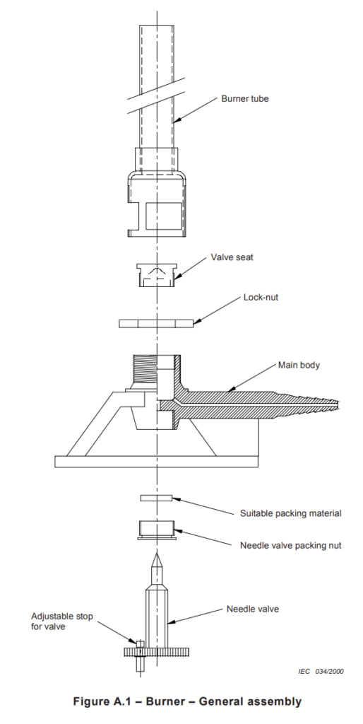
The burner consists essentially of:
- burner tube;
- main body;
- valve seat / gas injector;
- needle valve;
- needle-valve packing arrangement;
- lock nut;
- adjustable needle-valve stop;
- adjustable air inlet.
The burner tube, gas injector and needle valve are removable for cleaning. During reassembly, particular attention must be paid to the needle-valve tip and its alignment with the valve seat. Damage or incorrect alignment can influence gas regulation and consequently flame performance.
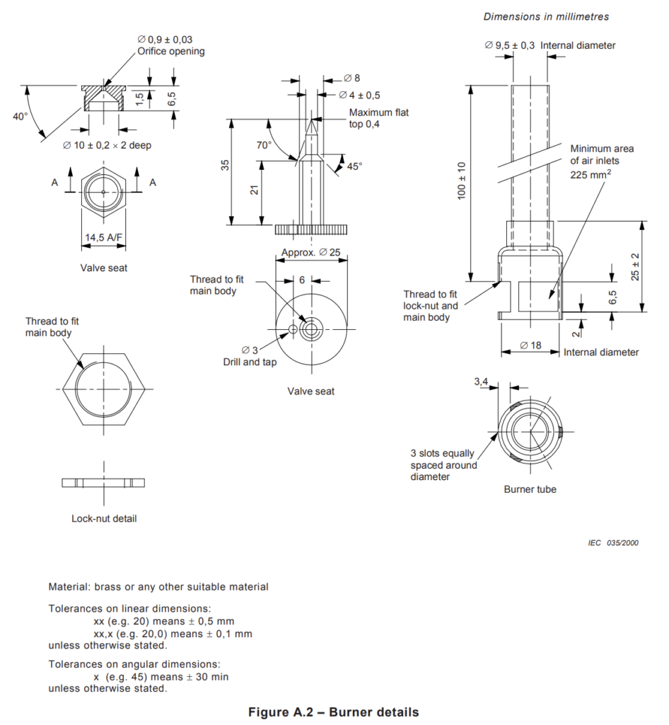
4. BURNER TUBE — DIMENSIONAL REQUIREMENTS
According to the detailed burner drawing, the burner tube includes the following principal dimensions:
Internal diameter: 9.5 ± 0.3 mm
Tube length: 100 ± 10 mm
The lower body has an internal diameter of: 18 mm
The burner incorporates: 3 slots equally spaced around the diameter
to provide the adjustable air supply.
The minimum total area of the air inlets shall be: 225 mm²
The burner material is specified as: Brass or another suitable material
unless otherwise required by the particular component.
Correct burner geometry is important because the air entrainment, gas/air mixing and resulting thermal output depend directly on these dimensions.
5. GAS INJECTOR / VALVE SEAT
One of the most critical burner dimensions is the gas orifice.
Orifice Diameter : Ø 0.9 ± 0.03 mm
The valve-seat geometry also includes a maximum flat at the top of: 0.4 mm
and the detailed valve-seat geometry and angular dimensions shall follow the standard burner drawing.
Because the injector geometry directly affects gas velocity and mixing, substituting an arbitrary commercial burner nozzle is not sufficient unless equivalent conformity can be demonstrated.
6. BURNER DIMENSIONAL TOLERANCES
Unless another tolerance is explicitly stated on the burner drawing.
7. GAS SUPPLY SYSTEM
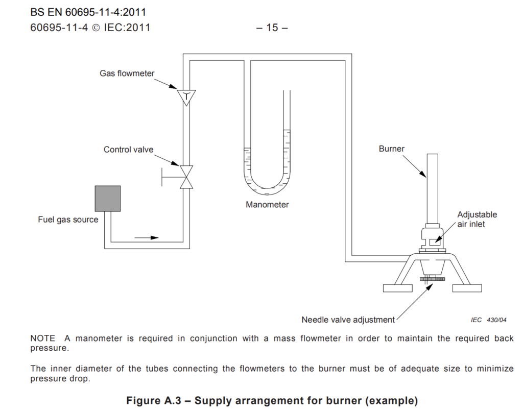
The burner supply arrangement consists of:
Fuel Gas Source → Control Valve → Gas Flowmeter → Pressure Measurement → Burner
The burner additionally incorporates:
- needle-valve adjustment;
- adjustable air inlet.
The internal diameter of tubing connecting the flowmeter to the burner must be sufficiently large to minimize pressure drop. All gas connections shall be leak-free.
8. FLOWMETER REQUIREMENTS
The flowmeter shall be suitable for measurement of the required methane flow: 105 ml/min at: 23 °C and 0.1 MPa
with an accuracy/tolerance of: ±2 %
A mass flowmeter is identified as the preferred method for accurately controlling the fuel input.
Other flow-control methods may be used only when equivalent accuracy can be demonstrated.
9. PRESSURE MEASUREMENT
A manometer shall be suitable for measuring: 0 to 7.5 kPa
A water manometer may be used provided that it is appropriately adapted for this measuring range.
The expected burner back pressure is: less than approximately 10 mm water column
When a mass flowmeter is used, a manometer is still required in order to maintain the necessary burner back pressure.
10. GAS CONTROL
A separate control valve is required for setting the gas flow.
Fine adjustment of the burner operating condition is performed using the burner needle valve together with the adjustable air inlet.
Stable and repeatable control of both parameters is necessary because the confirmation test depends on the actual thermal output of the flame rather than simply the indicated gas-flow value.
11. FUEL GAS SPECIFICATION
The required fuel is: Methane with purity: ≥ 98 %
Gas composition should therefore be treated as part of the controlled test condition.
Using another fuel or an inadequately controlled methane mixture would not constitute the standardized flame defined by this method.
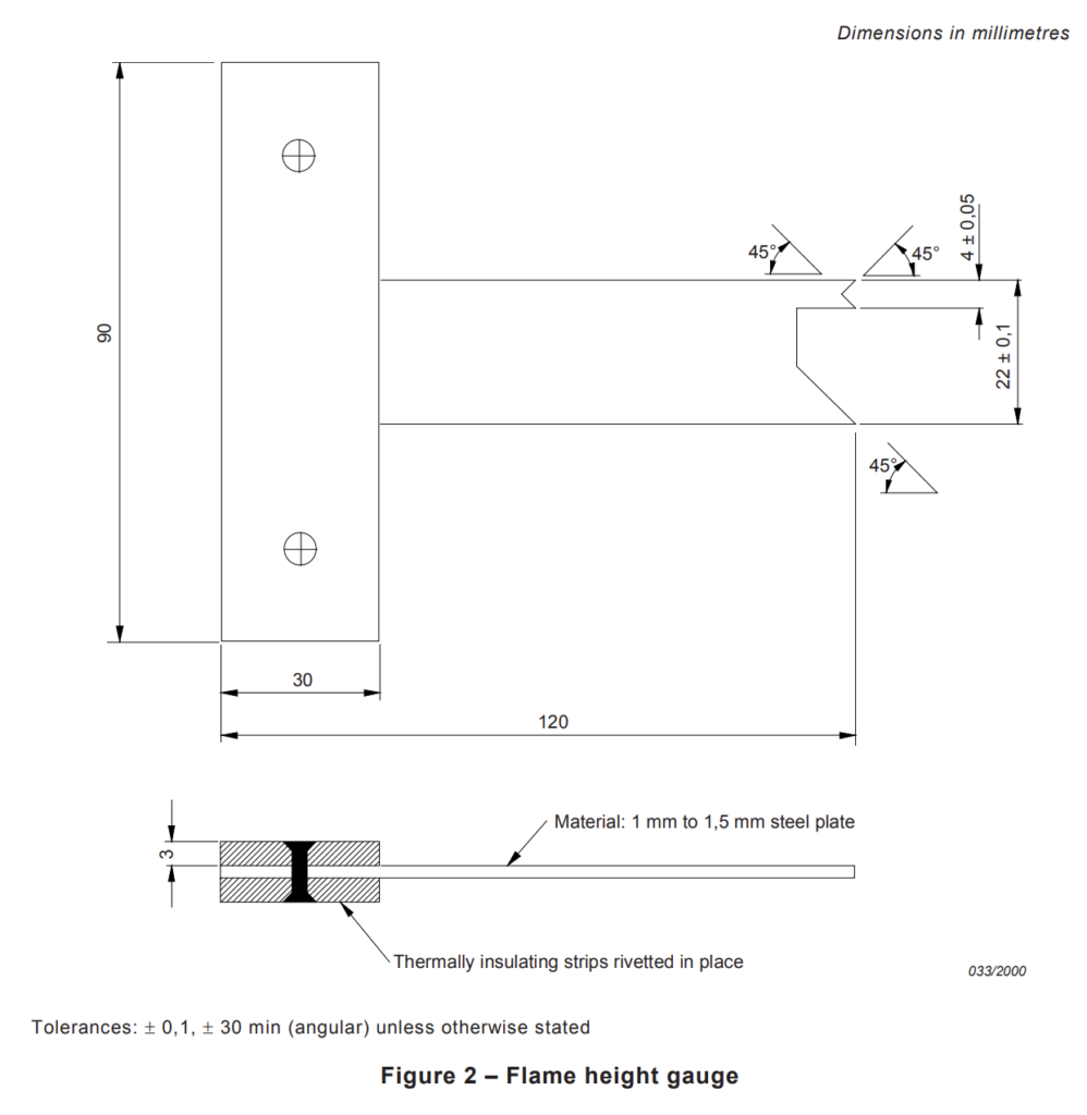
12. FLAME HEIGHT GAUGE
Flame height is checked using the specified flame-height gauge.
The gauge is manufactured from: 1.0 mm to 1.5 mm steel plate
with thermally insulating strips incorporated into the design.
Principal dimensions shown for the gauge include:
- Overall body height: 90 mm
- Body width: 30 mm
- Overall reach: 120 mm
- Flame reference dimension: 22 ± 0.1 mm
- Additional reference dimension: 4 ± 0.05 mm
- Reference faces: 45°
Unless otherwise specified:
- Linear tolerance: ±0.1 mm
- Angular tolerance: ±30 min
The gauge provides a repeatable reference for adjusting the overall flame height toward the nominal 20 mm condition.
13. COPPER CONFIRMATION BLOCK
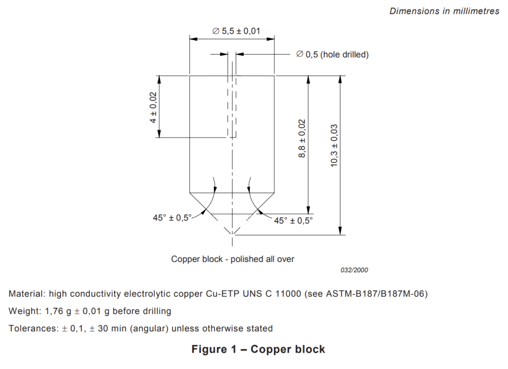
The standardized flame is thermally verified using a precision copper block.
This component is critical because it converts flame heat input into a measurable temperature-rise time.
Material High-conductivity electrolytic copper: Cu-ETP / UNS C11000
Nominal Diameter Ø 5.5 mm
The detailed drawing specifies: Ø 5.5 ± 0.01 mm Mass
Before drilling: 1.76 ± 0.01 g
Thermocouple Hole Ø 0.5 mm
Important Dimensions
The detailed copper-block drawing specifies, among others:
- 10.3 ± 0.03 mm
- 8.8 ± 0.02 mm
- 4 ± 0.02 mm
- lower machining angles of 45° ± 0.5°
The block shall be polished all over.
Unless otherwise stated on the drawing:
- dimensional tolerance: ±0.1 mm
- angular tolerance: ±30 min
14. COPPER BLOCK CONTROL
The standard does not specify a separate verification method for the copper block itself.
Instead, laboratories are encouraged to maintain:
- a standard reference unit;
- a secondary standard reference unit;
- a working unit;
and to cross-compare them as appropriate in order to verify the working system.
This is particularly important because changes in copper-block geometry, mass or surface condition can directly influence the measured heating time.
15. THERMOCOUPLE REQUIREMENTS
Temperature of the copper block is measured using a: mineral-insulated, metal-sheathed fine-wire thermocouple
with an: insulated junction
The thermocouple shall comply with: IEC 60584-2, Class 1
Nominal Overall Diameter 0.5 mm
An example is: Type K — NiCr/NiAl in accordance with IEC 60584-1.
The welded measuring point is located inside the sheath.
The sheath material shall withstand continuous operation at: ≥ 1,050 °C
A nickel-based heat-resistant alloy such as an appropriate high-temperature alloy can satisfy this requirement.
16. THERMOCOUPLE INSTALLATION
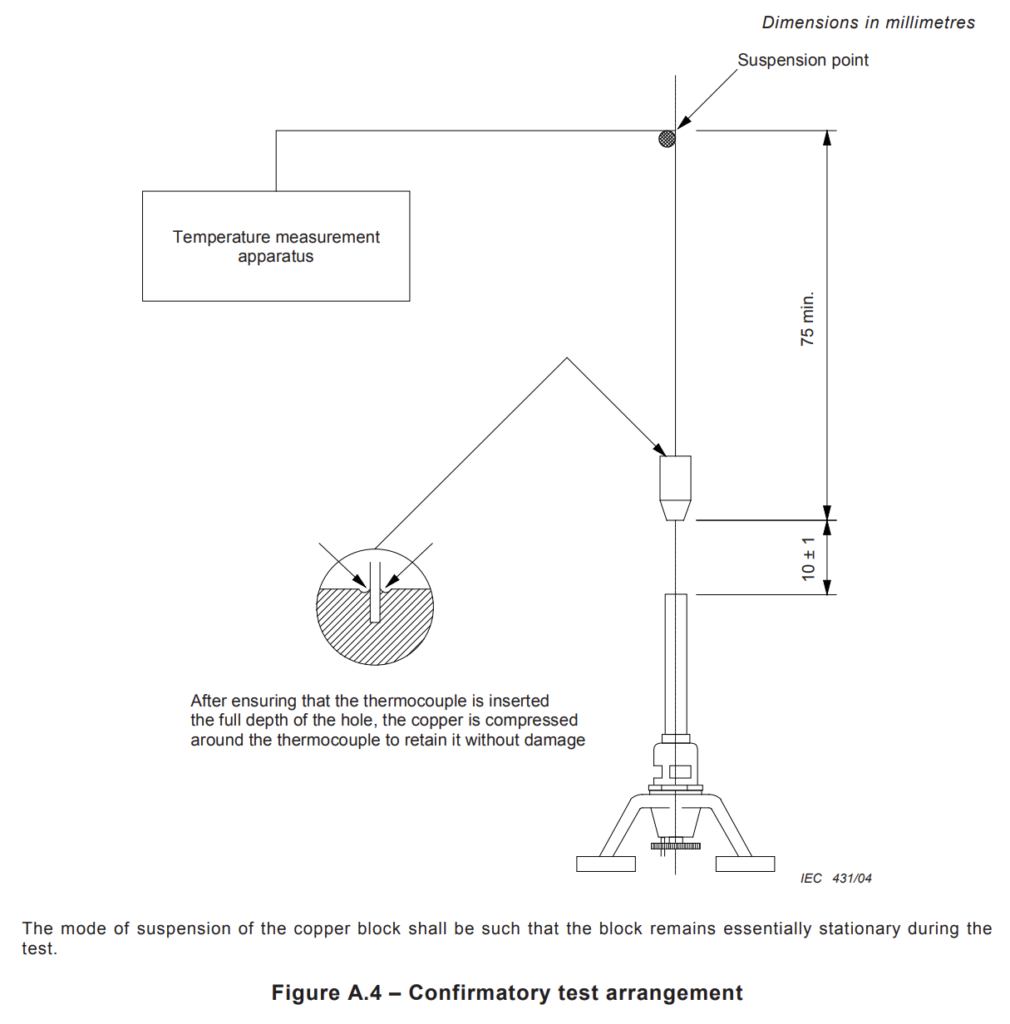
The thermocouple shall be inserted to the full depth of the copper-block hole.
The preferred retention method is to compress the copper locally around the thermocouple so that it remains securely retained without damaging the sensor.
Correct installation is important because poor thermal contact or an incorrect sensing position can change the measured heating response.
17. TEMPERATURE AND TIME RECORDING SYSTEM
The temperature/time indicating or recording equipment shall be suitable for determining the time required for the copper block to rise from: 100 ± 2 °C to: 700 ± 3 °C
The permissible tolerance of the measured time is: ±0.5 s
Therefore, the measurement system must provide adequate temperature response, time resolution and data acquisition performance for this relatively short heating interval.
18. LABORATORY TEST CHAMBER
The burner and confirmation test shall be operated inside a suitable laboratory fumehood or chamber.
Unless otherwise specified by the relevant burning-behaviour test method, the chamber shall have an internal volume of at least: 0.5 m³
The chamber shall:
- allow observation of the test;
- provide a draught-free environment;
- allow normal thermal circulation of air around the specimen;
- have dark-coloured internal walls.
A draught-free environment is essential because even relatively small air movement can alter flame geometry and heat transfer.
19. CHAMBER LIGHTING
With a lux meter facing toward the rear of the chamber and positioned at the location normally occupied by the test flame, the measured light level shall be: < 20 lx
This requirement provides suitable visual conditions for observation of the flame and specimen.
20. EXHAUST SYSTEM
For safety, the chamber may be equipped with an extraction system such as an exhaust fan to remove potentially toxic combustion products.
However: The extraction system shall be OFF during the test.
It shall be switched ON: immediately after completion of the test
to remove combustion products.
A positive-closing damper may also be necessary.
The exhaust must not disturb the flame while measurements are being performed.
21. INITIAL BURNER SETUP
Install the gas supply and burner according to the specified arrangement.
Before ignition:
- verify correct burner assembly;
- verify correct gas supply;
- check tubing;
- confirm adequate tubing diameter;
- verify flowmeter and pressure measurement;
- ensure all gas connections are leak-free;
- place the burner inside the specified chamber.
22. PRODUCTION OF THE TEST FLAME
Ignite the methane. Adjust the gas flow to the required value. The needle valve is used to establish the required gas-flow condition. Then adjust the air inlet. The air supply shall be adjusted until the flame becomes: completely blue
with: no inner cone
The final flame shall appear: stable and symmetrical
and its overall height shall comply with the specified requirement.
23. TARGET FLAME HEIGHT
The overall flame height should normally be: 18–22 mm
with adjustment targeted toward: 20 mm
Measurement is performed using the specified flame-height gauge inside the laboratory chamber.
Flame height alone, however, is not the final calibration criterion.
The thermal confirmation test must also be passed.
24. PRINCIPLE OF FLAME CONFIRMATION
The confirmation test measures the thermal effect of the flame on the standardized copper block.
The burner is positioned below the suspended copper block according to the specified confirmation geometry.
The time required to raise the block temperature from: 100 ± 2 °C
to: 700 ± 3 °C is measured. Required result: 44 ± 2 s
25. CONFIRMATORY TEST GEOMETRY
The copper block shall be suspended so that it remains essentially stationary during the test.
The standard confirmation arrangement shows:
- suspension point above the block;
- minimum suspension length/reference of 75 mm;
- burner positioned vertically below the copper block;
- a specified burner-to-block relationship including the 10 ± 1 mm dimension shown in the confirmation arrangement;
- thermocouple connected to the temperature measurement apparatus.
The physical arrangement shall follow the specified confirmation drawing rather than being established only by visual flame contact.
26. COMPLETE FLAME CONFIRMATION PROCEDURE
Step 1 — Assemble the System
Set up the burner supply system and confirmation apparatus according to the specified arrangements inside the laboratory chamber.
Ensure that all gas connections are leak-free.
Step 2 — Protect the Copper Block During Adjustment
Temporarily move the burner away from the copper block.
This prevents preliminary flame adjustment from heating the block.
Step 3 — Ignite the Flame
Ignite the methane and adjust the gas flow to the required condition.
Step 4 — Adjust the Air Supply
Rotate/adjust the burner air inlet until the: yellow tip just disappears
This is an important operational criterion for establishing the required premixed flame.
Step 5 — Verify Flame Geometry
Check that:
- overall flame height is within the required limits;
- flame is symmetrical;
- operating condition is stable.
Step 6 — Thermal Stabilization
Allow the burner to operate for at least: 5 minutes
before performing the confirmation measurement.
This allows the burner operating conditions to reach equilibrium.
Step 7 — Verify Gas Flow Again
After stabilization, measure the gas flow and confirm that it remains within the specified limits.
Step 8 — Start Measurement
Ensure that the temperature/time indicating or recording system is operational.
Reposition the burner underneath the copper block.
Step 9 — Measure Heating Time
Determine the elapsed time for the copper block to increase from: 100 ± 2 °C → 700 ± 3 °C
Step 10 — Evaluate the Result
Required heating time: 44 ± 2 s
Equivalent acceptable interval: 42–46 s
27. THREE SUCCESSIVE RESULTS ARE REQUIRED
One successful heating cycle is not sufficient.
When the first determination falls within: 44 ± 2 s
the procedure shall be repeated two additional times.
The flame is confirmed only when: three successive determinations
are all within specification.
28. COOLING BETWEEN DETERMINATIONS
Between successive measurements, the copper block shall be allowed to cool: naturally in air
until its temperature is: below 50 °C
Only then should the next determination be performed.
Artificially changing the prescribed cooling process can affect repeatability and should not replace the specified natural-air cooling condition.
29. WHAT IF A RESULT FAILS?
If any determination is outside: 44 ± 2 s
the flame shall be adjusted.
After adjustment:
- allow the flame to reach equilibrium again;
- restart the confirmation procedure.
The requirement is therefore not “three acceptable tests out of several attempts.”
The requirement is: three successive compliant determinations.
30. NEW COPPER BLOCK CONDITIONING
If the copper block has never previously been used: perform a preliminary heating run to condition its surface.
The result of this preliminary run shall be: discarded
and shall not count as one of the three required confirmation determinations.
31. HIGH-TEMPERATURE PRECAUTION
The thermocouple can be readily damaged at temperatures above: 700 °C
For this reason, the burner should be removed promptly once the copper block reaches the upper measurement temperature.
32. FINAL ACCEPTANCE CRITERIA
The flame is confirmed for test use only when all essential conditions have been established and the thermal confirmation requirement has been satisfied.
The key confirmation criterion is:
Copper Block: 100 ± 2 °C → 700 ± 3 °C
Heating Time: 44 ± 2 s
Required Repetitions: 3 successive compliant determinations
In practical terms:
42 s ≤ each result ≤ 46 s
for all three successive determinations.
33. APPARATUS DESIGNATION
Apparatus conforming to the requirements of IEC 60695-11-4 and capable of producing the standardized flame may be identified as:
“50 W nominal test flame apparatus, conforming to IEC 60695-11-4.”
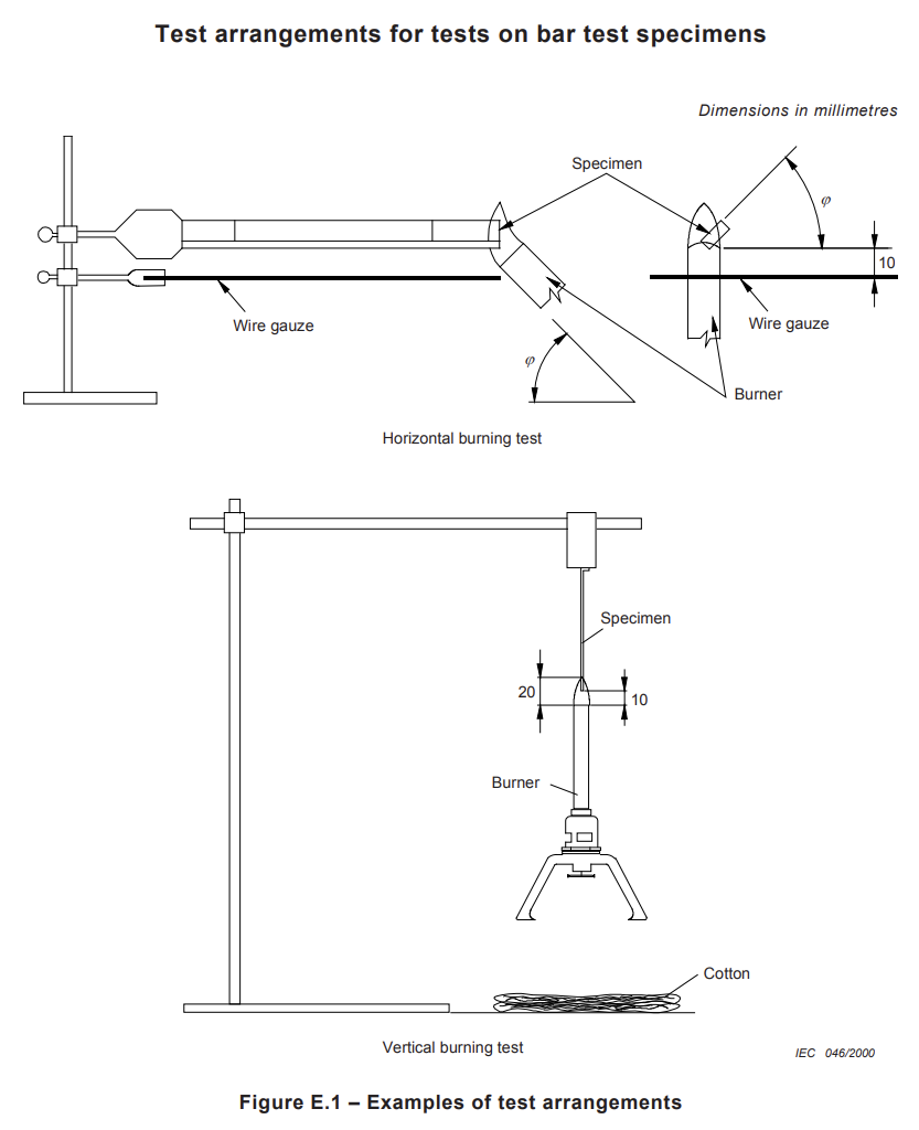
34. RECOMMENDED USE FOR EQUIPMENT TESTING
For testing equipment, the recommended distance between: the top of the burner tube
and: the point on the specimen surface being tested
is: 20 mm
unless another requirement is specified by the relevant product standard.
The burner may be tilted by: 45° or less
and fixed in position during the test.
The applicable product standard ultimately determines the exact flame application conditions.
35. RECOMMENDED USE FOR BAR-SHAPED MATERIAL SPECIMENS
For bar test specimens, the recommended distance from the top of the burner tube to the test point is: 10 mm
unless otherwise specified by the relevant standard.
The operator may move the flame during testing to follow a specimen that distorts or burns.
The 10 mm spacing was selected to improve reproducibility compared with simply maintaining contact between the flame tip and the specimen.
36. FALLING DEBRIS
Where necessary, the burner may be tilted so that burning or molten debris from the specimen does not fall directly into the burner.
This helps prevent interference with burner operation during the test.
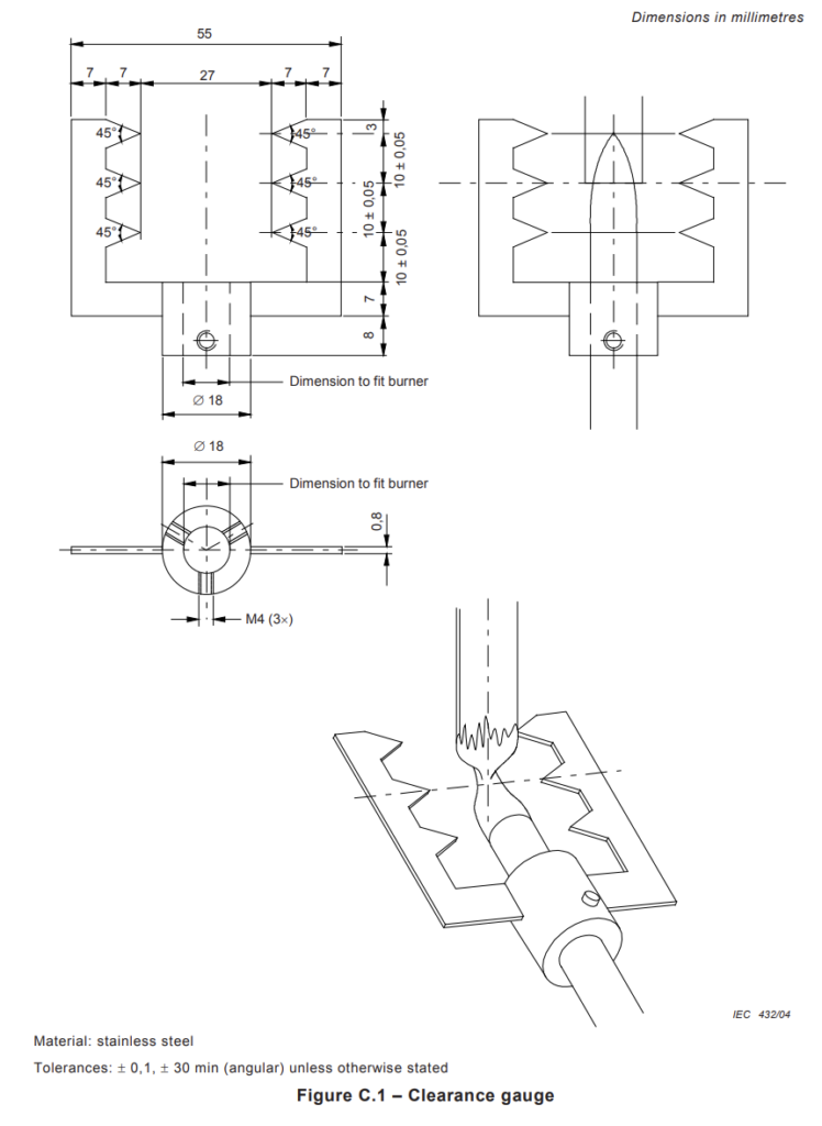
37. CLEARANCE GAUGE
IEC 60695-11-4 also provides a clearance-gauge design that may be attached to the top of the burner tube.
Its purpose is to help the operator maintain the specified burner-to-specimen distance.
The gauge is manufactured from: stainless steel
and incorporates reference distances of: 10 ± 0.05 mm
with detailed geometry and mounting dimensions defined in the standard.
38. APPLICATION TO EQUIPMENT
When testing equipment, the test flame is normally applied to an internal surface at a location considered likely to ignite because of proximity to a potential ignition source.
Where ventilation openings are involved, the flame may be applied to an opening. Otherwise, it is applied to a solid surface.
For the arrangements illustrated for equipment testing, the flame tip should just touch the test specimen.
If a vertical component is involved, the flame may be applied at a convenient angle from the vertical.
For materials inside a fire enclosure, application to an external surface is permitted where the physical size prevents internal application.
39. IMPORTANT DISTINCTION — FLAME STANDARD VS PRODUCT TEST STANDARD
IEC 60695-11-4 primarily defines: how the standardized 50 W flame is produced and confirmed.
It does not, by itself, establish universal pass/fail criteria for every material or finished product.
The relevant product or material standard must specify matters such as:
- specimen geometry;
- conditioning;
- flame application position;
- flame application duration;
- number of applications;
- afterflame criteria;
- afterglow criteria;
- dripping/ignition criteria;
- final product acceptance requirements.
Therefore, compliance of the 50 W flame apparatus with IEC 60695-11-4 should not be confused with compliance of a material or product with a separate flammability requirement.
40. PRACTICAL PRE-TEST CHECKLIST
Before using the 50 W flame for an actual test, the operator should verify at minimum:
✓ Correct IEC burner geometry
✓ Burner clean and correctly assembled
✓ Gas injector/orifice compliant
✓ Needle valve undamaged and correctly aligned
✓ Air inlet operating correctly
✓ Methane purity ≥98 %
✓ Corrected methane flow = 105 ± 5 ml/min
✓ Flow measurement capability ±2 %
✓ Pressure measurement available
✓ Leak-free gas connections
✓ Correct flame-height gauge
✓ Flame approximately 20 mm high
✓ Flame stable and symmetrical
✓ Correct blue flame condition
✓ No inner cone under the production condition
✓ Correct copper-block material, dimensions and mass
✓ 0.5 mm Class 1 thermocouple
✓ Thermocouple fully inserted into the copper block
✓ Suitable temperature/time acquisition system
✓ Timing measurement tolerance ±0.5 s
✓ Draught-free chamber
✓ Chamber volume ≥0.5 m³ where applicable
✓ Background illumination <20 lx
✓ Exhaust OFF during measurement
✓ Burner stabilized for ≥5 min before confirmation
✓ Copper block cooled naturally below 50 °C between runs
✓ Three successive heating times within 42–46 s
41. WHY THE CONFIRMATION TEST MATTERS
A common mistake in flame testing is to focus only on: “Is the flame 20 mm high?”
But flame height alone does not define the standardized 50 W test flame.
Two flames with apparently identical dimensions may deliver different thermal energy because of differences in:
- gas flow;
- gas composition;
- injector dimensions;
- burner geometry;
- air entrainment;
- gas pressure;
- burner temperature;
- flame adjustment;
- environmental airflow.
IEC 60695-11-4 therefore uses the copper-block heating response as a practical confirmation of the complete flame system. The essential concept can be summarized as:
Control the geometry → Control the fuel → Control the airflow → Stabilize the burner → Verify the flame dimensions → Confirm the thermal output.
Only after successful thermal confirmation should the flame be used for the intended fire-hazard test.
- Digital timer
- Rotameter type flow controller
- Gas pressure indicator
- Automatic flame application on sample piece
- Chamber size according to the standard
- Sample positioning 2 axes linear mechanism
- Copper block and measurement unit with WINDOWS software for verification of flame is as option (Not included in standard delivery)
- Nominal flame power: 50 W
- Flame type: Premixed
- Fuel: Methane (to be supplied by customer)
- Methane purity: ≥98 %
- Gas flow: 105 ± 5 ml/min at 23 °C, 0.1 MPa
- Flowmeter tolerance: ±2 %
- Manometer range: 0–7.5 kPa
- Typical flame height: 18–22 mm
- Target flame height: ≈20 mm
- Burner tube ID: 9.5 ± 0.3 mm
- Burner tube length: 100 ± 10 mm
- Gas orifice: Ø0.9 ± 0.03 mm
- Minimum air-inlet area: 225 mm²
- Copper block diameter: 5.50 mm
- Copper block mass: 1.76 ± 0.01 g before drilling
- Thermocouple: 0.5 mm, Class 1
- Temperature interval: 100 ± 2 °C → 700 ± 3 °C
- Required heating time: 44 ± 2 s
- Timing tolerance: ±0.5 s
- Required confirmation: 3 successive compliant results
- Cooling between runs: naturally to <50 °C
- Burner stabilization: ≥5 min
- Minimum chamber volume: 0.5 m³, unless otherwise specified
- Chamber illumination: <20 lx
- Recommended equipment spacing: 20 mm
- Recommended bar-specimen spacing: 10 mm