

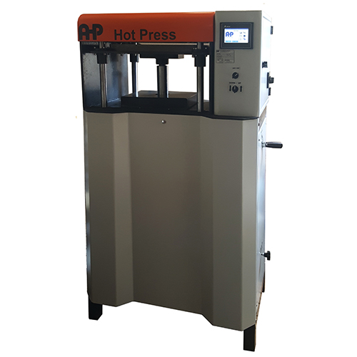
How to specify the laboratory hydraulic hot press, mould, force capacity, temperature control and cooling system for technically defensible specimen preparation.
| Machine-selection conclusion: For ISO 293:2023, the decisive press requirements are not simply “a hot press”. The system must deliver at least 12 MPa cavity pressure, hold the specified pressure within ±10%, heat the platens to at least 320 °C, maintain mould-surface temperature uniformity within ±2 °C during heating and ±4 °C during cooling, and execute the selected cooling method. AHP’s hydraulic hot-press platform is the correct machine architecture. |
1. What ISO 293:2023 is trying to control
ISO 293:2023 defines the preparation of compression-moulded thermoplastic test specimens and sheets from which specimens can subsequently be machined or stamped. The purpose is reproducibility of specimen state: compression moulding is used to obtain homogeneous, isotropic specimens where the starting material itself permits that condition. The 2023 edition also emphasizes that cooling through the crystallization region strongly affects semi-crystalline and crystalline polymers such as PE, PP and PB, making cooling control a specimen-conditioning variable rather than a secondary machine function.
The document is not applicable to reinforced thermoplastics. For each polymer, the moulding temperature and cooling method still have to come from the relevant material standard or an agreement between the interested parties. Therefore, ISO 293 defines the press capability envelope and preparation logic; it does not provide one universal temperature/pressure recipe for every thermoplastic.
2. Press requirements that directly drive machine specification
| Parameter | ISO 293:2023 requirement | Engineering implication |
| Cavity pressure capability | ≥ 12 MPa | Force must be sized from mould cavity area, not platen size. |
| Pressure stability | Within ±10% of specified pressure | Closed-loop or monitored hydraulic pressure is strongly preferred. |
| Maximum platen temperature | At least 320 °C | The 2023 edition raises the capability requirement from the older 240 °C level. |
| Temperature uniformity – heating | Any mould-surface points within ±2 °C | Requires uniform platen design, suitable heater zoning and validated sensor placement. |
| Temperature uniformity – cooling | Any mould-surface points within ±4 °C | Cooling-channel geometry and coolant flow balance become critical. |
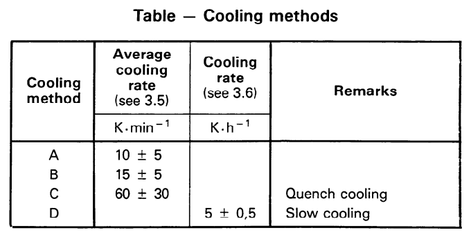
| Cooling capability | According to ISO 293 | |
| Quench cooling – Method C | ||
| Temperature measurement | Near the moulded material | Continuous control may be taken in the centre between upper and lower platens; mould thermocouple holes are permitted. |
3. Force sizing: the most common mistake in selecting the press
ISO 293 defines pressure conventionally as clamping force divided by mould cavity area. The minimum required force is therefore:
Fmin [kN] = 12 [N/mm²] × Acavity [mm²] ÷ 1000
| Example cavity | Area (mm²) | Minimum force at 12 MPa (kN) | Practical press class* |
| 100 × 100 mm square cavity | 10,000 | 120.0 | ≥ 150 kN nominal class |
| 120 × 120 mm square cavity | 14,400 | 172.8 | ≥ 200 kN nominal class |
| 150 × 150 mm square cavity | 22,500 | 270.0 | ≥ 300 kN nominal class |
| 170 × 170 mm square cavity (size mentioned in ISO 293:2023 Note 2) | 28,900 | 346.8 | ≥ 350 kN nominal class |
| Ø 200 mm round cavity | 31,416 | 377.0 | ≥ 400 kN nominal class |
*Practical class is an engineering selection aid, not an ISO requirement; final sizing should include the machine manufacturer’s usable-force range and process margin.
| Critical example: A 100 × 100 mm cavity needs 120 kN merely to reach 12 MPa. A 100 kN press reaches only 10 MPa and is therefore below the ISO 293:2023 minimum for that cavity. A 150 kN hydraulic press provides 15 MPa nominal capability on the same cavity. By contrast, a 170 × 170 mm cavity requires 346.8 kN at 12 MPa, so a 300 kN press is not sufficient if pressure is calculated over the full 170 × 170 mm cavity area. |
4. Which AHP machine architecture is appropriate?
The appropriate AHP platform is the hydraulic hot press, not the manual hot press, when ISO 293 pressure repeatability and controlled cooling are required. For example take note below comments on some force range of our hot presses and take note when you are going to place order for definite sample area.
| AHP nominal force | Max cavity area at 12 MPa (mm²) | Equivalent square side | Selection comment |
| 50 kN | 4,167 | 64.5 × 64.5 mm | Too small for a 100 × 100 mm ISO-style sheet cavity at 12 MPa. |
| 100 kN | 8,333 | 91.3 × 91.3 mm | Still below the 120 kN required for a 100 × 100 mm cavity. |
| 150 kN | 12,500 | 111.8 × 111.8 mm | Suitable force range for a 100 × 100 mm cavity, subject to temperature/cooling configuration. |
| 200 kN | 16,667 | 129.1 × 129.1 mm | Provides more force margin for medium laboratory moulds. |
| 300 kN | 25,000 | 158.1 × 158.1 mm | Cannot reach 12 MPa over a full 170 × 170 mm cavity; larger cavity requires a higher-force/custom press. |
5. Thermal system: 320 °C is only the first requirement
A compliant temperature system must do more than reach 320 °C. ISO 293:2023 limits the temperature difference between points on the mould surfaces to ±2 °C during heating and ±4 °C during cooling. This requirement makes platen construction, heater distribution, sensor location, mould contact quality and cooling-channel symmetry part of the test-specimen quality chain.
- Use independent temperature measurement close to the moulded material. Blind thermocouple holes in the mould are explicitly contemplated by the standard.
- Validate surface uniformity across the useful moulding area, not only at the controller sensor.
- Use balanced coolant channels and a repeatable flow-control strategy. ISO 293:2023 requires the heat-transfer-fluid flow rate for a specified cooling method to be predetermined in a trial without material in the mould.
- For semi-crystalline polymers, treat cooling-rate control as a material-structure control parameter because crystallization history affects final physical properties.
6. Mould choice changes the stress state of the specimen
ISO 293:2023 distinguishes flash (picture-frame) moulds and positive moulds. The mould choice is not merely geometric: it changes whether pressure remains on the polymer during cooling, and therefore changes thickness, density, internal stress and void formation.
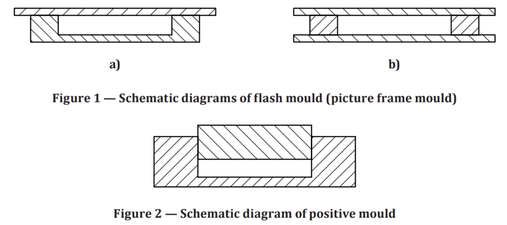
Figure 1 flash mould and Figure 2 positive mould. Included here for internal editorial review. ISO reproduction permission should be confirmed before publishing these figures on a public website.
| Mould type | Pressure during cooling | Primary benefit | Important limitation / design point |
| Flash / picture-frame | Pressure acts on the frame, not the polymer | Comparable low internal stress; economical sheet moulding | Centre can become slightly thinner due to shrinkage; direct bars can show sink marks/voids; use central sheet area for machining. |
| Positive mould | Full moulding pressure maintained on polymer, neglecting friction | Consolidated mouldings, flat surfaces, suppression of voids | Thickness/stress/density depend strongly on charge mass, mould clearances, pressure and cooling history. |
For flash moulds, ISO 293:2023 specifies approximately 4-5 mm upper and lower plates, polished steel or chromium-plated brass, with aluminium or polyester flexible foil permitted to reduce sticking. Release agent is not allowed. The outer 20 mm perimeter of the moulded sheet is excluded from the main test area. For positive moulds, the standard recommends H7g6 guidance for a round cavity; for a 200 mm diameter cavity this corresponds to a stated clearance range of 15-90 µm. Ejection pins may be used.
7. Mould fabrication details that matter to test validity
- Mould materials must withstand both moulding temperature and pressure.
- Recommended contact-surface roughness is 0.16 Ra; chromium plating can improve release.
- A 2° taper is strongly recommended for small specimens.
- ISO 293:2023 notes alloy steel heat-treated to 2,200 MPa tensile strength as generally satisfactory; for PVC, martensitic stainless steel treated to 1,050 MPa is recommended.
- For most ISO 20753 specimen types, ISO 293:2023 notes that a 170 × 170 mm square positive cavity can provide enough specimens for one test per moulding; however, that cavity size has major implications for press force, requiring 346.8 kN at the ISO 293 minimum pressure.
8. Process control sequence and what the machine must record
The specimen-preparation procedure is not just a press cycle. ISO 293:2023 treats material condition, mould type, thermal history, pressure history and cooling history as controlled variables. A technically defensible preparation sequence should therefore be written and executed as a traceable process recipe rather than as a simple “heat-and-press” operation.
8.1 Establish the material-specific moulding condition before starting
ISO 293:2023 does not prescribe one universal moulding temperature or one universal cooling method for every thermoplastic. The required moulding temperature and the applicable cooling method are taken from the relevant International Standard for the material or are agreed between the interested parties. This is especially important for semi-crystalline polymers such as PE and PP, because the cooling rate through the crystallization region can materially change the final properties of the specimen.
8.2 Prepare and dry the moulding material
For granular material, first follow the drying conditions in the relevant material standard or the material supplier’s instructions. If no drying instruction is available, ISO 293:2023 specifies either 24 h ± 1 h at 70 °C ± 2 °C in a conventional oven, or 16 h ± 1 h at 80 °C ± 2 °C in a vacuum oven. The dried material should be protected from moisture pick-up before moulding.
Direct moulding from granules is the standard route when a sufficiently homogeneous sheet can be obtained. The sheet should be free from visible surface irregularities and internal imperfections. Where granules or powder do not produce adequate homogeneity, a preform route may be required; the polymer must not be thermally or mechanically degraded during any pre-processing operation.
8.3 Prepare the mould and verify the moulding surfaces
Select either a flash (picture-frame) mould or a positive mould according to the required specimen state. The mould surfaces contacting the polymer should be polished; ISO 293:2023 recommends a surface roughness of 0.16 Ra. Chromium plating may be used to facilitate release, and a 2° taper is strongly recommended for small specimens. For flash moulds, flexible aluminium or polyester foil may be used to prevent sticking, but a release agent is not allowed.
For positive moulds, pressure is maintained on the polymer during cooling. The standard recommends an H7g6 fit for a round male/female mould pair; for a 200 mm diameter round cavity, the stated clearance range is 15 µm to 90 µm. Temperature-measurement holes may be incorporated so that the temperature is measured close to the moulded material rather than inferred only from a remote heater sensor.
8.4 Set up and qualify the press before loading material
Before each defined preparation program, confirm that the press can generate a cavity pressure of at least 12 MPa and maintain the selected pressure within ±10% during the moulding cycle. Confirm that the platens can reach at least 320 °C and that the mould-surface temperature variation is within ±2 °C during heating and ±4 °C during cooling. These are machine-system requirements, not optional process targets.
For the selected cooling method, predetermine the heat-transfer-fluid flow rate in a trial without moulding material. This separates the cooling-system capability from the thermal response of a particular polymer charge and makes the cooling programme reproducible.
8.5 Load the material and begin preheating under contact pressure
Place the prepared material in the preheated mould in a way that promotes uniform filling and thermal exposure. Close the press initially at contact pressure: this is a low pressure used to keep the mould closed while the material heats to the specified moulding temperature, without intentionally forcing full material flow. ISO 293:2023 defines the preheating time as the time required for the material in the mould to reach the moulding temperature while contact pressure is maintained.
The temperature used for process control should be measured in the nearest practical vicinity to the moulded material. The machine recipe should therefore distinguish platen heater setpoint from actual mould/material-zone temperature.
8.6 Apply full moulding pressure and hold the moulding condition
Once the material has reached the specified moulding temperature, apply full moulding pressure. The moulding time is the period during which full pressure is applied while the moulding temperature is maintained. During this stage, the actual pressure must remain within ±10% of the specified pressure. Pressure, mould temperature and moulding time should be stored as recipe variables and recorded for traceability.
The exact moulding temperature, preheating duration and moulding duration are material-dependent process conditions. ISO 293:2023 requires the material-specific condition to come from the applicable material standard or from an agreed procedure; they should not be replaced by one generic time/temperature recipe for all polymers.
8.7 Execute the specified cooling method as a controlled part of the moulding cycle
Cooling is a controlled processing stage because it can change crystallinity, residual stress, density and mechanical properties. ISO 293:2023 standardizes eight cooling methods and distinguishes between average (non-linear) cooling rate and controlled (linear) cooling rate. The selected method must therefore be programmed and documented as part of the specimen preparation, not treated as an uncontrolled “cool until safe to handle” step.
For average cooling rate, the rate is evaluated from the moulding temperature, demoulding temperature and cooling time. For controlled cooling rate, the coolant flow is regulated so that the specified rate is maintained over the defined temperature range within its tolerance. For Method C quench cooling, ISO 293:2023 requires two presses: one for heating/moulding and one for cooling, so transfer time and safe mould handling become part of the equipment concept.
8.8 Demould only at the specified end-of-cooling condition
Demoulding temperature is the mould or platen temperature at the end of the cooling period, measured near the moulded material. Demoulding should therefore be triggered by the specified thermal endpoint, not merely by elapsed time. The selected demoulding temperature and cooling method must be included in the specimen-preparation record.
8.9 Inspect the moulded sheet or specimen before machining or testing
After cooling and demoulding, verify surface condition and dimensional conformity before the sheet is accepted for machining/stamping or the directly moulded specimen is released for testing. Reject any preparation showing moulding defects, dimensional non-conformity or evidence of polymer degradation. For flash-moulded sheets, specimens should be taken from the qualified central test area rather than the outer 20 mm perimeter.
8.10 Record the complete preparation recipe
The preparation record should identify the material, specimen/sheet geometry, mould type, surface/foil arrangement, drying condition, preform preparation if used, moulding temperature, preheating time, moulding pressure, moulding time, cooling method, cooling-rate control condition, demoulding temperature and any relevant observation. These variables are the minimum technical data needed to reproduce the thermal and pressure history of the specimen.
ISO 293:2023 specimen-preparation control sequence for an AHP hydraulic hot press configuration.
| Step | Control point | Requirement / action | What to record |
| 1 | Material condition | Material standard / supplier drying instruction; fallback drying: 24 h ± 1 h at 70 °C ± 2 °C, or 16 h ± 1 h at 80 °C ± 2 °C in vacuum oven | Drying temperature, time, oven type |
| 2 | Mould preparation | Correct mould type; polished contact surfaces; no release agent for flash mould; sensor point close to material | Mould ID/type, foil, surface condition |
| 3 | Press qualification | ≥12 MPa available cavity pressure; pressure maintained within ±10%; platen capability ≥320 °C | Cavity area, force setpoint, pressure trace |
| 4 | Thermal uniformity | Mould-surface variation ≤±2 °C during heating and ≤±4 °C during cooling | Temperature map / validation record |
| 5 | Preheating | Contact pressure maintained until the material reaches specified moulding temperature | Preheat time and actual mould-zone temperature |
| 6 | Moulding | Full pressure applied while maintaining moulding temperature | Pressure, temperature, moulding time |
| 7 | Cooling | Use the specified ISO 293 cooling method; predetermine coolant flow; control rate as applicable | Cooling method, flow setting, cooling curve |
| 8 | Demoulding | End cooling at the specified demoulding temperature measured near the material | Demoulding temperature |
| 9 | Inspection & release | Accept only conforming, defect-free mouldings/sheets; use qualified test area | Dimensions, visual acceptance, observations |
9. Why an older “ISO 293 press” may no longer be enough
| Item | 1986 edition in supplied archive | 2023 edition | Machine consequence |
| Minimum cavity pressure | 10 MPa | 12 MPa | 20% higher minimum pressure capability. |
| Minimum platen temperature capability | 240 °C | 320 °C | Older presses capped around 240-300 °C may fail the current requirement. |
| Cooling methods | 4 methods | 8 methods | Current machine must support a broader/revised cooling-control framework. |
| Flash-mould plate thickness | About 1-2 mm | About 4-5 mm | Mould hardware guidance has changed. |
| Default drying option when no instruction exists | 24 h ±1 h at 70 °C ±2 °C oven | Same oven option plus 16 h ±1 h at 80 °C ±2 °C vacuum oven | Vacuum oven option added. |
10. Recommended AHP quotation / FAT checklist for an ISO 293:2023 configuration
- Nominal hydraulic force selected from actual cavity area so that ≥12 MPa is available at the mould cavity.
- Pressure monitoring and control demonstrate ±10% or better stability at the specified moulding pressure.
- Platens are rated to at least 320 °C for the offered configuration.
- Mould-surface temperature mapping demonstrates ≤±2 °C variation during heating over the useful area.
- Cooling mapping demonstrates ≤±4 °C variation during cooling over the useful area.
- Water-cooling circuit, valve/control logic and chiller capacity are sized for the selected ISO 293 cooling method.
- Cooling-fluid flow setting can be predetermined and reproduced.
- Thermocouple measurement is available close to the moulded material or at the specified central platen location.
- PLC recipe stores preheat, moulding pressure/time, temperature profile and cooling sequence; data logging is recommended for traceability. If recording is needed machine will be supplied with a computer and software.
- If Method C quench cooling is required, quote a two-press arrangement or a validated equivalent workflow consistent with the standard requirement for two presses.
- Mould type (flash or positive), cavity dimensions, foil, surface finish, temperature-sensor holes and ejection arrangement are specified on the same quotation.
11. Engineering conclusion
For ISO 293:2023, the laboratory press is part of the measurement system. If force is undersized, platen temperature is too low, surface temperature is non-uniform, or cooling is uncontrolled, the resulting sheet can have a different morphology, density, residual stress or void content – and downstream tensile, impact, DSC or other material-test results may no longer represent the intended standardized specimen state.
For AHP PLASTIK MAKINA, the technically correct solution is a hydraulic hot press engineered around the customer’s mould area and polymer family. A 150 kN or 200 kN platform can be appropriate for a 100 × 100 mm cavity, while larger sheet moulds require correspondingly higher force. For a 170 × 170 mm cavity, the ISO minimum pressure alone requires approximately 347 kN, so a ≥400 kN class/custom hydraulic system is the defensible selection. The thermal package must additionally be specified for at least 320 °C and validated heating/cooling uniformity, with controlled water cooling matched to the selected ISO 293:2023 cooling method.