
Introduction
ASTM D412 is a widely used testing standard for evaluating the tensile properties of vulcanized rubber and thermoplastic elastomers (TPEs). The test determines how rubber-like materials respond to tensile loading, including their strength, elongation, stress at specified elongations, yield behavior and permanent deformation.
Tensile testing is an essential quality control procedure in the rubber industry, particularly for manufacturers of seals, gaskets, hoses, flexible components, molded rubber products and thermoplastic elastomer compounds.
ASTM D412-16 (2021) describes two principal methods:
- Test Method A: Dumbbell-shaped and straight specimens.
- Test Method B: Cut ring specimens.
These methods use different specimen geometries and may produce different results. Therefore, the specimen type and test method must be identified when comparing material properties.
1. Scope and Application of ASTM D412
ASTM D412 applies to vulcanized thermoset rubbers and thermoplastic elastomers. It is not intended for ebonite or similar hard, low-elongation materials.
The standard enables laboratories to determine:
- Tensile strength and tensile stress
- Tensile stress at specified elongations, such as 100%, 200% or 300%
- Ultimate elongation at break
- Yield stress and yield strain, where applicable
- Tensile set
- Tensile set after break
These properties help manufacturers evaluate material consistency, compound formulation, vulcanization quality and mechanical performance.
Because rubber is sensitive to temperature, deformation rate, specimen geometry and conditioning, comparisons should be made under equivalent testing conditions.
2. Tensile Testing Machine Requirements
A power-driven universal tensile testing machine is required to perform ASTM D412 testing.
2.1 Crosshead Speed and Travel
According to Section 6.1 of ASTM D412, the testing machine shall provide:
| Parameter | Standard requirement |
|---|---|
| Grip separation speed | 500 ± 50 mm/min |
| Minimum grip separation travel | 750 mm |
| Force measurement accuracy | Within ±2% of applied force |
| Elongation measurement increments | 10% or smaller |
| Force calibration | ASTM E4, Procedure A |
A grip separation rate of 1000 ± 100 mm/min is permitted under the standard’s stated conditions, provided it is reported. In cases of dispute, testing is repeated at 500 ± 50 mm/min.
For materials exhibiting a yield point below 20% elongation, the standard requires reduced testing speeds of 50 ± 5 mm/min and, if necessary, 5 ± 0.5 mm/min.
2.2 Load Cell and Force Measurement
The tensile testing machine must incorporate a suitable force-measuring system.
The load cell should be selected according to the expected tensile forces of the material and specimen dimensions.
For example, a specimen with a cross-sectional area of 12 mm² and a tensile strength of 20 MPa produces an approximate breaking force of: F = 20 × 12 = 240 N
A load cell with a suitable calibrated measurement range is therefore important for obtaining accurate results.
Engineering recommendation: Interchangeable load cells, such as 100 N, 500 N, 1 kN and 5 kN, can provide flexibility for testing materials with different mechanical properties. These capacities are examples of equipment configuration options, not capacities prescribed by ASTM D412.
The machine should record force continuously throughout the test, including the maximum force and force at rupture.
2.3 Tensile Grips
Correct gripping is particularly important when testing elastomeric materials.
ASTM D412 specifies grips that prevent slippage and distribute gripping pressure uniformly.
For dumbbell specimens, suitable options include:
- Self-tightening grips that increase gripping pressure as tensile force increases
- Constant-pressure pneumatic grips
Straight specimens may use appropriate pneumatic, wedge or toggle grips.
Improper gripping can cause premature failure near the jaws, inaccurate elongation measurements or specimen slippage.
2.4 Elongation Measurement System
Rubber specimens can undergo substantial elongation before rupture.
ASTM D412 requires measurement of elongation during testing. For dumbbell specimens, strain should be determined from the change in distance between the gauge marks.
An extensometer is the preferred approach for accurately measuring elongation at specified stress levels.
Suitable measurement technologies may include:
- Non-contact video extensometers
- Optical tracking systems
- Contact extensometers designed for highly extensible materials
Important: Crosshead displacement is not necessarily equivalent to specimen gauge-length elongation. Machine compliance, grip movement and specimen deformation outside the gauge length can introduce errors.
For accurate stress-at-elongation results, direct measurement of the specimen gauge length is recommended.
3. Specimen Preparation — Test Method A
3.1 Dumbbell Specimens
Dumbbell-shaped specimens are commonly used for tensile testing of rubber materials.
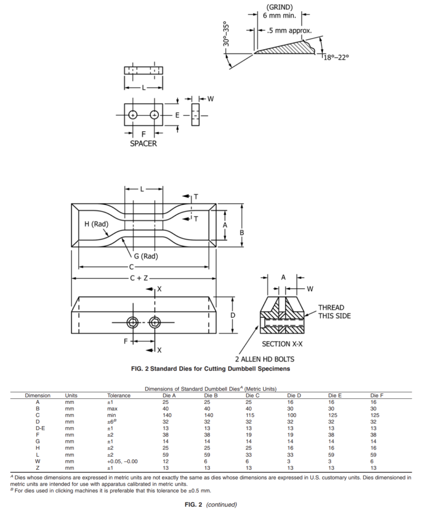
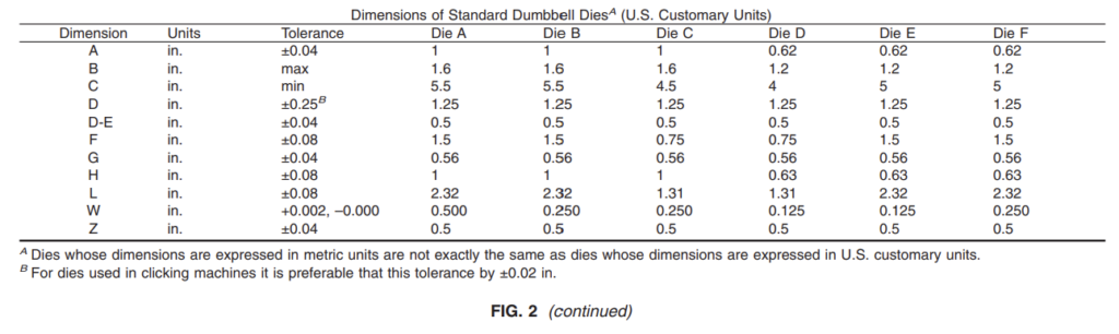
ASTM D412 provides six standard cutting die geometries, designated Die A through Die F.
For conventional dumbbell specimens, the standard specifies a sheet thickness range of 1.3–3.3 mm.
For thermoplastic rubber and thermoplastic elastomer specimens prepared from injection-molded sheets, the specified thickness is generally 3.0 ± 0.3 mm unless otherwise stated.
Compression molding is the preferred specimen preparation method described in the standard.
3.2 Standard Dumbbell Die Dimensions
Selected metric dimensions from Figure 2 of ASTM D412 are presented below.
| Die type | Narrow section width | Minimum die length |
|---|---|---|
| Die A | 12 mm | 140 mm |
| Die B | 6 mm | 140 mm |
| Die C | 6 mm | 115 mm |
| Die D | 3 mm | 100 mm |
| Die E | 3 mm | 125 mm |
| Die F | 6 mm | 125 mm |
The complete die geometry, including transition radii and dimensional tolerances, must follow the standard drawing.
Die C is commonly used for preparing dumbbell specimens from molded sheets unless another geometry is specified.
3.3 Gauge Length
The original distance between the gauge marks depends on the selected cutting die.
| Specimen geometry | Initial gauge length |
|---|---|
| Die C and Die D | 25.00 ± 0.25 mm |
| Die A, B, E and F | 50.00 ± 0.50 mm |
Gauge marks must be placed symmetrically within the reduced section of the specimen.
The specimen must not be stretched while the marks are applied.
3.4 Thickness Measurement
Thickness must be measured at three positions:
- Center of the reduced section.
- One end of the reduced section.
- Opposite end of the reduced section.
The median of these three measurements is used to calculate the original cross-sectional area.
Specimens must be rejected when the difference between maximum and minimum thickness exceeds 0.08 mm.
The original cross-sectional area is calculated as:
A₀ = w × t
Where:
- A₀ = Original cross-sectional area (mm²)
- w = Width of the reduced section (mm)
- t = Median specimen thickness (mm)
4. Specimen Conditioning and Test Temperature
Environmental conditions can significantly affect the tensile properties of rubber.
The standard test temperature is: 23 ± 2°C
Specimens must be conditioned for at least 3 hours at the standard test temperature.
For moisture-sensitive materials, the standard specifies:
- Relative humidity: 50 ± 5%
- Minimum conditioning time: 24 hours
For elevated-temperature testing, Method A specimens are preheated for 10 ± 2 minutes before testing.
For testing below 23°C, specimens are conditioned at the selected temperature for at least 10 minutes.
When testing at non-ambient temperatures, a suitable environmental chamber is required.
The chamber must maintain specimen temperature within ±2°C of the specified temperature and provide air circulation at 1–2 m/s near the grips.
5. ASTM D412 Tensile Test Procedure — Method A
The following procedure summarizes the principal testing operations.
Step 1 — Prepare the Specimens
Prepare the dumbbell specimens using the appropriate standard cutting die.
Inspect each specimen for surface defects, irregular cutting edges, damage and thickness variations.
Step 2 — Measure the Dimensions
Measure the specimen thickness at three locations and determine the median value.
Record the reduced section width and calculate the original cross-sectional area.
Step 3 — Mark the Gauge Length
Apply the required gauge marks according to the selected specimen geometry.
Step 4 — Configure the Testing Machine
Select the appropriate load cell and gripping system.
Set the grip separation speed to 500 mm/min, unless another rate is required by the standard’s applicable provisions.
Verify the force measurement system and elongation measurement arrangement.
Step 5 — Install the Specimen
Place the specimen centrally between the upper and lower grips.
Ensure that the specimen is aligned with the tensile loading direction and that gripping pressure is sufficient to prevent slipping without damaging the specimen.
Step 6 — Start the Test
Start the tensile testing machine and continuously record tensile force and elongation.
Observe the specimen for slipping, abnormal deformation or premature failure near the grips.
Step 7 — Record the Results
Record the force at the specified elongations and at rupture.
Determine the maximum force where required and measure ultimate elongation.
For Method A, elongation at rupture is recorded to the nearest 10%.
Step 8 — Calculate and Report
Calculate the tensile properties from the recorded force, original cross-sectional area and measured elongation.
Identify the specimen type, test speed, temperature and other relevant testing conditions.
6. Tensile Stress and Elongation Calculations
6.1 Tensile Stress
Engineering tensile stress is calculated using the original cross-sectional area:
σ = F / A₀
Where:
- σ = Tensile stress (MPa)
- F = Applied tensile force (N)
- A₀ = Original cross-sectional area (mm²)
Since 1 N/mm² equals 1 MPa, the result can be expressed directly in MPa.
6.2 Tensile Strength
Tensile strength under ASTM D412 is determined using the force at rupture:
TS = F_break / A₀
It is important to distinguish the breaking force from the maximum force if the force decreases before rupture.
6.3 Percentage Elongation
Percentage elongation is calculated as:
E (%) = [(L − L₀) / L₀] × 100
Where:
- L₀ = Original gauge length
- L = Gauge length during extension
For example, if a specimen has an original gauge length of 25 mm and reaches 125 mm:
E = [(125 − 25) / 25] × 100
Elongation = 400%
6.4 Stress at Specified Elongation
Rubber compounds are frequently characterized by their stress at predetermined elongations.
Examples include:
- Stress at 100% elongation
- Stress at 200% elongation
- Stress at 300% elongation
These values are sometimes referred to in industry as M100, M200 and M300.
For example, if a specimen has an original cross-sectional area of 12 mm² and the force at 100% elongation is 36 N:
Stress at 100% elongation = 36 / 12
Result = 3.0 MPa
These values are useful for comparing the stiffness and tensile response of rubber compounds.
7. Tensile Set and Set After Break
ASTM D412 also provides procedures for determining residual deformation.
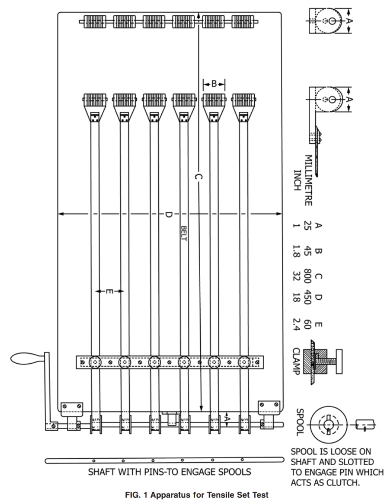
7.1 Tensile Set
For the tensile set procedure, the specimen is extended to a specified elongation over approximately 15 seconds.
The specimen is held at that elongation for 10 minutes.
The load is then released, and the specimen is allowed to recover for 10 minutes.
The remaining elongation is measured and expressed as a percentage of the original gauge length.
Tensile Set (%) = [(L_recovered − L₀) / L₀] × 100
This property indicates how much deformation remains after stretching and recovery.
7.2 Set After Break
Set after break is measured 10 minutes after the tensile specimen ruptures.
The two broken pieces are carefully brought together at the fracture surface, and the distance between the original gauge marks is measured.
The residual elongation is then calculated relative to the original gauge length.
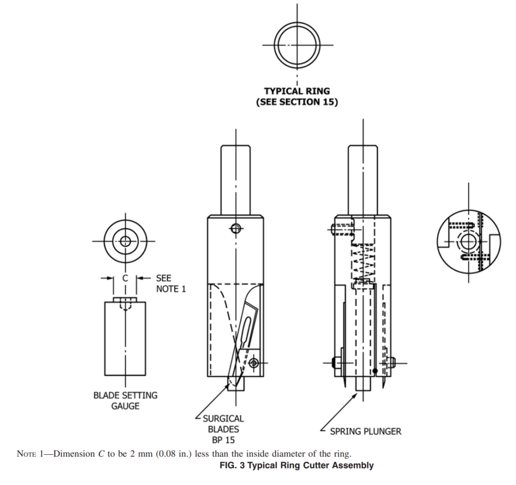
8. ASTM D412 Test Method B — Cut Ring Specimens
Method B uses ring-shaped specimens rather than dumbbell specimens.
Ring specimens are particularly useful for certain rubber sheets, tubing and other applications where ring-shaped specimens are appropriate.
The standard defines two ASTM cut ring geometries.
| Parameter | Type 1 | Type 2 |
|---|---|---|
| Inside diameter | 15.92 mm | 29.8 mm |
| Radial width | 1.0 mm | 2.0 mm |
| Thickness range | 1.0–3.3 mm | 1.0–3.3 mm |
Unless otherwise specified, Type 1 rings are used.
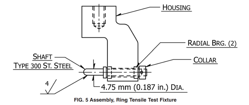
The ring is mounted over two cylindrical spindles, which separate during testing.
The general spindle separation speed is 500 ± 50 mm/min.
For the small ISO ring geometry referenced by the standard, the spindle separation speed is 100 ± 10 mm/min.
Special Considerations for Ring Testing
Unlike dumbbell specimens, ring specimens experience nonuniform strain across their radial width.
The standard therefore specifies different geometric references for calculating elongation at a specified stress and elongation at rupture.
For stress at specified elongation, the mean ring circumference is used.
For ultimate elongation, the inside circumference is used.
Ring testing requires an appropriate spindle fixture and correct initial spindle spacing.
Results from Method A and Method B should not be treated as interchangeable.
9. Recommended Technical Features for a Rubber Tensile Testing Machine
For laboratories performing ASTM D412 testing, the following equipment configuration is recommended.
| Component | Recommended configuration |
|---|---|
| Machine type | Motorized universal tensile testing machine |
| Test control | Constant-rate grip separation |
| Test speed | Adjustable to cover applicable ASTM D412 speeds |
| Travel | At least 750 mm grip separation |
| Force measurement | Calibrated load cell, accuracy within ±2% of applied force |
| Grip system | Self-tightening or pneumatic rubber specimen grips |
| Strain measurement | Suitable extensometer or optical elongation measurement |
| Data acquisition | Continuous force and elongation recording |
| Software | Stress–strain analysis and test report generation |
| Specimen preparation | ASTM D412 dumbbell cutting dies |
| Ring testing | Optional ring specimen fixture |
| Temperature control | Optional environmental chamber |
These recommendations describe an appropriate laboratory configuration. They should not be interpreted as verified specifications of a particular AHP machine model.
Recommended Software Functions
A modern tensile testing software package can simplify ASTM D412 testing by providing:
- Automatic recording of force and elongation
- Real-time force–extension curves
- Engineering stress–strain curves
- Calculation of tensile strength
- Calculation of elongation at break
- Stress values at user-defined elongation percentages
- Identification of yield behavior
- Storage of individual specimen measurements
- Calculation of median test results
- Export of reports and raw test data
Automatic reporting helps reduce manual calculation errors and improves traceability.
10. Number of Specimens and Evaluation of Results
ASTM D412 Method A specifies the preparation of five dumbbell specimens.
For routine testing, the reported result is generally the median of three individual measurements.
Five measurements are used for referee testing and in the specified compliance-testing circumstances where one or two of the initial three values fail the requirement.
The laboratory must apply the relevant specimen selection and result evaluation provisions of the standard.
11. Calibration and Quality Assurance
Force measurement calibration is performed according to ASTM E4, Procedure A.
The testing laboratory should also verify the relevant measurement and control systems, including:
- Applied tensile force
- Grip separation speed
- Elongation measurement
- Specimen dimensions
- Test temperature, where applicable
Calibration records and equipment identification should be maintained to support traceability.
The test equipment should be inspected regularly for grip wear, mechanical misalignment, abnormal vibration and specimen slippage.
12. Test Report Requirements
An ASTM D412 test report should include the relevant information specified in Section 18, including:
- Calculated tensile test results
- Specimen geometry and preparation method
- Dumbbell die type and dimensional unit system, where applicable
- Date of testing
- Test speed when different from the specified rate
- Temperature and humidity when different from standard conditions
- Test temperature when different from 23 ± 2°C
- Date of vulcanization or specimen preparation, if known
For improved laboratory traceability, additional information such as specimen identification, equipment serial number, calibration references and individual stress–strain curves can also be included.
13. Common Sources of Testing Error
Specimen Slippage
Insufficient grip pressure can produce inaccurate elongation measurements and inconsistent tensile results.
Incorrect Gauge Length Measurement
Using crosshead movement instead of actual gauge length extension can introduce significant strain measurement errors.
Poor Specimen Cutting
Damaged or blunt cutting dies can introduce edge defects that lead to premature failure.
Incorrect Test Speed
Rubber materials exhibit rate-dependent behavior. Incorrect grip separation speed can affect tensile strength and elongation.
Temperature Variation
Changes in test temperature can alter the mechanical response of elastomers.
Specimen Thickness Variation
Incorrect thickness measurement directly affects the calculated tensile stress and tensile strength.
Controlling these variables is essential for obtaining reliable and reproducible results.
14. Conclusion
ASTM D412 provides a standardized approach for evaluating the tensile properties of vulcanized rubber and thermoplastic elastomers.
Accurate testing requires correctly prepared specimens, controlled environmental conditions, suitable gripping fixtures, calibrated force measurement and reliable elongation measurement.
A properly configured universal tensile testing machine enables laboratories to determine tensile strength, stress at specified elongations, ultimate elongation and other important mechanical properties.
AHP PLASTIK MAKINA manufactures material testing equipment for plastics, rubber and polymer laboratories.
For information about tensile testing machines, suitable gripping fixtures and equipment configurations for ASTM D412 applications, contact AHP PLASTIK MAKINA.
