

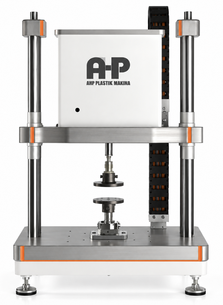
1. Introduction
The compression test is used to determine the resistance of conduit systems to transverse mechanical compression.
The test evaluates the ability of a conduit to withstand a specified compressive load without excessive permanent deformation, flattening, or visible cracking.
The general compression test requirements are specified in IEC 61386-1 – Conduit systems for cable management – Part 1: General requirements. The particular requirements for different conduit types are specified in:
- IEC 61386-21 – Particular requirements for rigid conduit systems
- IEC 61386-22 – Particular requirements for pliable conduit systems
The compression resistance forms part of the mechanical classification of the conduit system. IEC 61386-1 defines five compression resistance classifications: Very Light, Light, Medium, Heavy, and Very Heavy.
2. Principle of the Compression Test
A conduit specimen is positioned horizontally on a flat steel support. A steel intermediate piece is positioned centrally on top of the conduit specimen. A controlled compressive force is then applied vertically through the intermediate piece.
The force is increased progressively until the compression force corresponding to the declared classification of the conduit is reached.
The deformation of the conduit is determined by measuring its outside diameter before loading, under the specified compression force, and after removal of the load.
The basic arrangement specified in IEC 61386-1 is:
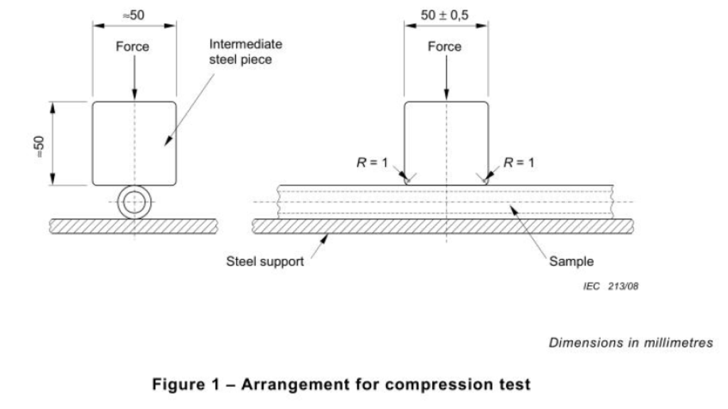
Figure 1 of IEC 61386-1 shows this compression arrangement and specifies the geometry of the steel intermediate piece.
3. Test Specimens
According to IEC 61386-1, three conduit specimens are subjected to the compression test.
Each specimen shall have a length of: 200 ± 5 mm
The test is normally performed at: 23 ± 2 °C
using the apparatus specified for the compression test.
For non-metallic and composite conduit systems, the general conditioning requirements of IEC 61386-1 shall also be considered. The standard specifies conditioning for at least 240 h at 23 ± 2 °C and relative humidity between 40% and 60%, unless otherwise specified.
4. Compression Test Apparatus
The compression test machine shall be capable of applying a controlled, uniformly increasing compressive force to the conduit specimen.
The principal components of the apparatus should include:
- Rigid mechanical loading frame
- Flat steel lower support
- Steel intermediate compression piece
- Precision force measurement system
- Controlled electromechanical loading mechanism
- Displacement measurement system
- Force and displacement display
- Programmable force ramp control
- Automatic test sequence
- Data acquisition and recording system
For a universal machine intended to cover all compression classifications of IEC 61386, the force measuring and loading system shall cover at least the maximum specified compression force of 4000 N.
A practical machine design therefore normally uses a load cell with a capacity above 4000 N, for example a 5 kN load cell, while maintaining adequate measurement accuracy at the lower force classifications.
5. Compression Plates and Loading Geometry
The conduit specimen shall rest on a flat steel support.
The compressive force is transmitted through a steel intermediate piece positioned in the middle of the specimen.
According to Figure 1 of IEC 61386-1, the intermediate steel piece has a nominal width of: 50 mm
and its lower longitudinal edges contacting the conduit have a radius of: R = 1 mm
The figure also specifies a nominal height of approximately 50 mm for the intermediate piece.
The loading system shall maintain proper alignment so that the compressive force acts vertically through the intermediate piece and approximately through the centre of the conduit specimen.
Misalignment can introduce bending or asymmetric deformation and should therefore be minimized by the mechanical design of the machine.
6. Initial Diameter Measurement
Before applying the compression force, the outside diameter of the conduit specimen shall be measured.
This initial diameter is designated: D₀ = Initial outside diameter
The diameter should be measured at the position where compression will subsequently occur.
This measurement is important because the acceptance criteria are expressed as percentage changes relative to the initial outside diameter.
IEC 61386-1 specifically requires the outside diameter of the sample to be measured before the test.
7. Compression Force Classification
The required compression force depends on the mechanical classification declared for the conduit.
| Classification | Description | Compression Force |
|---|---|---|
| 1 | Very Light | 125 N |
| 2 | Light | 320 N |
| 3 | Medium | 750 N |
| 4 | Heavy | 1250 N |
| 5 | Very Heavy | 4000 N |
The compression force values are specified with a tolerance of: 0 / +4%
Therefore, the applied force shall not fall below the nominal classification force.
For example, for a Medium classification conduit: Nominal force = 750 N
Permitted maximum force: 750 × 1.04 = 780 N
Therefore: 750 N ≤ F ≤ 780 N
8. Controlled Increase of Compression Force
The compression force shall not be applied suddenly.
IEC 61386-1 specifies a uniformly increasing compression force reaching the required value within: 30 ± 3 seconds
Therefore, the nominal loading time is 30 seconds, with an allowable range from: 27 to 33 seconds.
IEC 61386-21 and IEC 61386-22 provide additional guidance for achieving a uniform increase of force. Their Annex AA expresses this requirement in terms of the minimum, nominal and maximum rate of force increase.
9. Required Force Ramp Rates
For automated compression equipment, the force should preferably be controlled as a force ramp.
The nominal rate is: Nominal Force Increase Rate = Compression Force / 30 s
The allowable minimum rate corresponds to reaching the force in 33 seconds, while the maximum rate corresponds to reaching it in 27 seconds.
The specified values are:
| Compression Force | Minimum Rate | Nominal Rate | Maximum Rate |
|---|---|---|---|
| 125 N | 3.8 N/s | 4.2 N/s | 4.6 N/s |
| 320 N | 9.7 N/s | 10.7 N/s | 12.3 N/s |
| 750 N | 22.7 N/s | 25.0 N/s | 28.9 N/s |
| 1250 N | 37.9 N/s | 41.7 N/s | 46.1 N/s |
| 4000 N | 121.2 N/s | 133.3 N/s | 154.1 N/s |
Annex AA of both particular standards provides these rates specifically to assist in controlling a constantly increasing force.
For example, for a 750 N Medium classification test: Nominal loading rate = 25.0 N/s
At this rate: 25 N/s × 30 s = 750 N
The force-time profile should therefore be approximately linear:
Force
(N)

750 |                         ●
    |                      /
    |                   /
    |                /
    |             /
    |          /
    |       /
    |    /
  0 |●____________________________ Time
    0            30 s
The machine should therefore control the test according to force versus time, rather than simply moving the compression platen at an arbitrary constant crosshead speed.
10. Closed-Loop Force Control
For an automated compression tester, closed-loop force control is recommended.
The control system continuously compares: Actual Force
with: Target Ramp Force
For example, for the 750 N classification:
Target Force(t) = 25 × t
where:
- Force is expressed in N
- Time is expressed in seconds
- 0 ≤ t ≤ 30 s
The motor, actuator speed or force application cylinder pressure can then be continuously adjusted to maintain the required force ramp.
This is particularly important because different conduit materials and diameters can have significantly different stiffness characteristics. A fixed crosshead speed would therefore not necessarily produce the required linear increase in force. Another force application system with force rate control system can be applied.
11. Measurement Under Compression
When the specified compression force has been reached, the outside diameter of the conduit at the flattened portion shall be measured without removing the force.
This diameter can be designated: D₁ = Outside diameter under compression
IEC 61386-1 requires the diameter at the flattened portion to be measured after the force has been applied for: 60 ± 2 seconds
without removing the force.
Therefore, the sequence is:
Start
  ↓
Measure D₀
  ↓
Increase force uniformly
  ↓
Reach classification force in 30 ± 3 s
  ↓
Maintain specified force
  ↓
At 60 ± 2 s measure D₁
  ↓
Remove force and intermediate piece
  ↓
Wait 60 ± 2 s
  ↓
Measure D₂
12. Deformation Under Load
The deformation under compression is calculated from the difference between the initial outside diameter and the diameter measured at the flattened portion while the load is applied.
The percentage deformation can be expressed as:
Deformation Under Load (%) = [(D₀ − D₁) / D₀] × 100
The difference between the initial outside diameter and the diameter of the flattened sample shall not exceed: 25% of the initial outside diameter
during the compression test.
Therefore: D₀ − D₁ ≤ 0.25 × D₀
or equivalently: D₁ ≥ 0.75 × D₀
Example
If: D₀ = 20.00 mm
the maximum permitted reduction is:
20.00 × 0.25 = 5.00 mm
Therefore: D₁ must be ≥ 15.00 mm
13. Recovery After Removal of the Load
After the diameter under load has been determined:
- The force is removed.
- The steel intermediate piece is removed.
- The specimen is allowed to recover for 60 ± 2 seconds.
- The outside diameter at the previously flattened portion is measured again.
This recovered diameter can be designated: D₂ = Outside diameter after recovery
IEC 61386-1 requires this second measurement after removal of the force and intermediate piece.
14. Permanent Deformation Requirement
After the recovery period, the difference between the initial outside diameter and the recovered outside diameter shall not exceed:
10% of the initial outside diameter
Therefore: D₀ − D₂ ≤ 0.10 × D₀
or: D₂ ≥ 0.90 × D₀
The permanent deformation percentage may be calculated as: Permanent Deformation (%) = [(D₀ − D₂) / D₀] × 100
and the acceptance criterion is: Permanent Deformation ≤ 10%
Example
For: D₀ = 20.00 mm
minimum acceptable recovered diameter:
D₂ ≥ 20.00 × 0.90 = 18.00 mm
Therefore:
- D₂ = 18.5 mm → acceptable for this dimensional criterion
- D₂ = 17.5 mm → does not satisfy this dimensional criterion
15. Visual Examination
After completion of the compression test, the specimen shall also be visually examined.
IEC 61386-1 requires that the specimens show:
No cracks visible to normal or corrected vision without additional magnification.
Therefore, dimensional recovery alone is not sufficient for compliance. A specimen that satisfies the dimensional requirements but exhibits visible cracking does not satisfy the complete compression-test requirements.
16. Additional Requirements for Pliable Conduit – IEC 61386-22
IEC 61386-22 introduces an additional procedure for pliable conduit.
The intermediate steel piece is subjected to the uniformly increasing compression force corresponding to the declared classification over: 30 ± 3 seconds
The specimen shall flatten by between: 25% and 50% of its initial outside diameter.
If the specimen flattens by less than 25%, an additional test is performed.
The intermediate steel piece is lowered onto the specimen, the specimen is rotated through approximately 90° about its longitudinal axis, and the additional test is carried out on a new specimen.
A new specimen is then subjected to the uniformly increasing force until the measured force reaches the specified classification value within 30 ± 3 seconds.
If the sample then flattens by between 25% and 50%, the force and intermediate steel piece are removed.
Five minutes after removal, the outside diameter of the sample at the flattened portion is measured again.
The difference between the initial outside diameter and the outside diameter measured five minutes after removal of the load shall not exceed: 10% of the initial outside diameter
and the sample shall show no visible cracks under normal or corrected vision without magnification.
This Part 22 procedure should therefore be implemented as a separate selectable test mode in an automated compression testing machine.
17. Requirements for Rigid Conduit – IEC 61386-21
IEC 61386-21 applies the general IEC 61386-1 compression test requirements to rigid conduit systems and adds guidance concerning the uniform increase of compression force.
The force should reach the required classification level within the prescribed 30 ± 3 s interval.
Annex AA provides the corresponding minimum, nominal and maximum force increase rates for automated force-controlled testing.
18. Recommended Force Measurement System
For a machine covering all IEC 61386 compression classifications, the force measurement system should cover at least:
0–4000 N
A practical configuration is:
5 kN precision load cell
The force measurement chain may consist of:
Load Cell
   ↓
Precision Load Cell Amplifier
   ↓
High-Resolution ADC
   ↓
Digital Controller / PLC / PC
   ↓
Closed-Loop Force Control
The load cell should be mounted directly in the compression force path to minimize errors caused by friction or mechanical transmission losses.
The machine software should provide load-cell zeroing and calibration functions.
19. Recommended Displacement Measurement
Although the standard acceptance measurements are based on conduit outside diameter, an automated machine may additionally use a displacement transducer or crosshead position encoder.
A displacement measurement system can be used for:
- Monitoring conduit deformation
- Recording Force–Displacement curves
- Automatic determination of compression displacement
- Detection of unexpected collapse
- Comparison between different conduit materials
- Research and quality-control analysis
Suitable measurement technologies include:
- Linear encoder
- LVDT
- Digital position encoder
- High-resolution servo position feedback
For strict conformity assessment, however, the diameter measurements and acceptance criteria specified by the standard remain the relevant measurements.
20. Control System Requirements
For an automated IEC 61386 compression tester, the controller should provide:
- Automatic load-cell zeroing
- Selection of compression classification
- Automatic selection of target force
- Programmable force ramp
- Real-time force measurement
- Closed-loop force regulation
- Test timer
- Automatic hold period
- Diameter/displacement recording
- Automatic load release
- Recovery timer
- Pass/fail calculation
- Force-time graph
- Force-displacement graph where displacement measurement is installed
- Test report storage and export
The operator may select:
Very Light / Light / Medium / Heavy / Very Heavy
and the software automatically assigns the appropriate force and force-increase rate.
21. Automatic Test Sequence
A fully automated machine may implement the following sequence: Step 1 – Specimen preparation
Prepare a conduit specimen of: 200 ± 5 mm
Step 2 – Conditioning
Condition the specimen as required by IEC 61386-1 and the applicable particular standard.
Step 3 – Initial diameter
Measure and enter or automatically acquire: D₀
Step 4 – Specimen positioning
Place the conduit horizontally on the flat steel support.
Position the intermediate steel piece centrally above the specimen.
Step 5 – Pre-contact
Move the compression head downward at low speed until contact with the specimen is detected.
The contact threshold should be sufficiently low that it does not produce significant pre-compression.
Step 6 – Start force ramp
Start the test timer and increase the compression force uniformly.
For example:
Medium Classification

Target = 750 N
Nominal Ramp = 25.0 N/s
Target Time = 30 s
Permitted Time = 27–33 s
Step 7 – Reach target force
The controller detects when the selected compression force is reached.
Step 8 – Hold and measurement
Maintain the required force and perform the diameter measurement at the time specified by the applicable procedure.
Step 9 – Release
Remove the compression force and intermediate piece.
Step 10 – Recovery
Allow the specimen to recover for the period required by the applicable test procedure.
Step 11 – Final diameter
Measure: D₂
Step 12 – Visual examination
Check for visible cracks.
Step 13 – Result calculation
The software calculates the dimensional changes and evaluates the applicable acceptance criteria.
23. Test Results and Calculations
The test report should record at least:
Initial Diameter
D₀ [mm]
Diameter Under Compression
D₁ [mm]
Recovered Diameter
D₂ [mm]
Maximum Applied Force
Fmax [N]
Time to Reach Compression Force
tF [s]
Deformation Under Load
[(D₀ − D₁) / D₀] × 100 [%]Permanent Deformation
[(D₀ − D₂) / D₀] × 100 [%]Visual Condition
No visible cracks / Cracks detected
Final Result
Pass / Fail according to the applicable IEC 61386 requirement.
24. Typical Test Report Data
A comprehensive electronic report can include:
- Test standard
- Applicable Part: IEC 61386-21 or IEC 61386-22
- Product identification
- Manufacturer
- Batch number
- Conduit type
- Nominal conduit size
- Conduit construction: plain or corrugated
- Compression classification
- Test temperature
- Conditioning information
- Specimen number
- Initial outside diameter
- Compression force
- Force tolerance
- Actual maximum force
- Time to reach target force
- Actual average force ramp
- Diameter under load
- Percentage deformation under load
- Recovery time
- Diameter after recovery
- Permanent deformation percentage
- Visual crack inspection result
- Force-time graph
- Force-displacement graph, if available
- Individual specimen result
- Overall test result
- Test date
- Operator identification
25. Summary of Main Test Parameters
| Parameter | Requirement |
|---|---|
| Specimen quantity | 3 |
| Specimen length | 200 ± 5 mm |
| Standard test temperature | 23 ± 2 °C |
| Compression classifications | 125 / 320 / 750 / 1250 / 4000 N |
| Force tolerance | 0 / +4% |
| Force application | Uniformly increasing |
| Target loading time | 30 ± 3 s |
| Intermediate piece width | 50 mm |
| Intermediate piece edge radius | R = 1 mm |
| Maximum deformation under IEC 61386-1 basic procedure | 25% of initial OD |
| Recovery measurement | According to applicable Part/procedure |
| Final permanent deformation limit | 10% of initial OD |
| Visual requirement | No visible cracks without magnification |
The general specimen dimensions, compression forces, timing, deformation limits and post-test visual requirement are specified in Clause 10.2 of IEC 61386-1. The particular rigid- and pliable-conduit requirements are then applied through IEC 61386-21 and IEC 61386-22 respectively.
26. Applicable Standards
IEC 61386-1
Conduit systems for cable management – Part 1: General requirements
IEC 61386-21
Conduit systems for cable management – Part 21: Particular requirements – Rigid conduit systems
IEC 61386-22
Conduit systems for cable management – Part 22: Particular requirements – Pliable conduit systems
Technical Specifications
- Test Type: Pneumatic Compression Test
- Loading System: Pneumatic cylinder
- Maximum Applied Force: 4000 N
- Load Cell Capacity: 500 kgf (approximately 4.9 kN)
- Force Measurement: Electronic load cell
- Force Control: Force control using load cell feedback
- Pneumatic Control: Electronic proportional pneumatic valve
- Force Application: Automatically controlled compression force
- Force Increase Rate: Programmable and automatically controlled
- Standard Loading Profile: Uniformly increasing compression force
- Loading Time: 30 ± 3 s according to the applicable test procedure
- Compression Force Levels: 125 N, 320 N, 750 N, 1250 N and 4000 N
- Displacement Measurement: Linear displacement transducer
- Measured Parameters: Force, displacement and time
- Graph Display: Force-Time and Force-Displacement curves
- Data Acquisition: Real-time digital data acquisition
- Computer Communication: USB
- Control Software: Dedicated test software supplied with the machine
- Data Storage: Test results and measurement data can be stored
- Test Reporting: Automatic test report generation in Microsoft Word format
- Computer: Optional
- Compressed Air Preparation: Inlet air filter/regulator maintenance unit
- Test Control: Automatic test sequence and force-ramp control
- Applicable Standards: IEC 61386-1, IEC 61386-21 and IEC 61386-22
- Application: Compression testing of rigid and pliable conduit systems
- Software Functions: Test control, real-time monitoring, graph generation, data storage, result evaluation and report generation