

Applicable Standard: ISO 7686:2005
Application: Plastics pipes and fittings — Determination of opacity
Manufacturer: AHP PLASTIK MAKINA
Country of Origin: Türkiye
1. General Information
1.1 Introduction
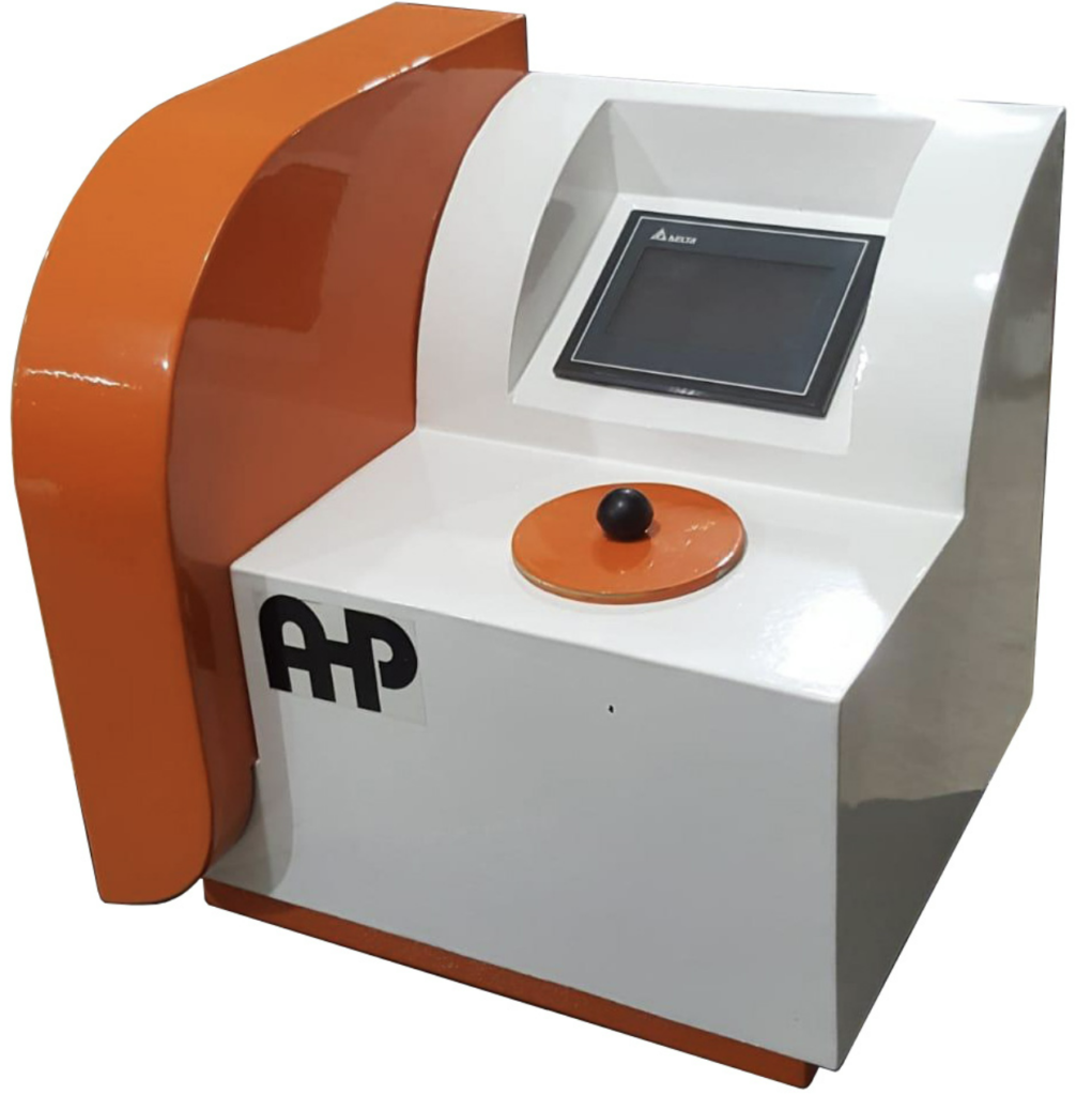
The AHP PLASTIK MAKINA Opacity Tester is designed for the determination of light transmission through the wall of plastics pipes and fittings.
The instrument is designed for testing in accordance with ISO 7686:2005 – Plastics pipes and fittings — Determination of opacity.
During the test, light is directed through a test piece prepared from the wall of a plastics pipe or fitting. The light transmitted through the specimen is measured by a photoelectric measuring system and compared with the maximum light intensity measured without the test piece.
The instrument incorporates an enclosed optical measurement chamber, light source, optical system, photoelectric detector, specimen positioning arrangement, electronic measurement system, and touchscreen HMI.
The enclosed measurement chamber minimizes the influence of ambient light and provides controlled optical conditions during measurement.
1.2 Intended Use
The AHP PLASTIK MAKINA Opacity Tester is intended for laboratory determination of the percentage of incident light transmitted through the wall of plastics pipes and fittings.
The instrument is intended for use by trained laboratory personnel under controlled laboratory conditions.
The equipment shall only be used for its intended purpose and in accordance with the instructions given in this manual.
1.3 Applicable Standard
The primary applicable standard is:
ISO 7686:2005
Plastics pipes and fittings — Determination of opacity
Where additional requirements or acceptance criteria are specified by the relevant product standard, those requirements shall also be considered when evaluating the test result.
2. Principle of the Test
2.1 General Principle
The test is based on measuring the scattered and unscattered light passing through a test piece taken from a plastics pipe or fitting.
The test piece is positioned in the optical path between the light source and the photoelectric detector.
The light intensity transmitted through the test piece is measured and compared with the maximum light intensity measured without the test piece.
2.2 Measurement Wavelength
In accordance with ISO 7686:2005, the measurement is performed using light within the wavelength range: 540 nm to 560 nm
The optical system is designed to restrict the measurement to the required wavelength range.
2.3 Measurement Values
The following values are used for determination of light transmission:
Imax = Maximum light intensity measured in the absence of the test piece.
I = Light intensity transmitted through the wall of the test piece.
2.4 Calculation
The percentage of incident light transmitted through the test piece is calculated as follows:
T = (I / Imax) × 100
Where:
- T = Percentage of incident light transmitted through the test piece, %
- I = Light intensity transmitted through the test piece
- Imax = Maximum light intensity measured without the test piece
3. Equipment Description
3.1 General Description
The AHP PLASTIK MAKINA Opacity Tester is a laboratory instrument incorporating the optical, electronic, and mechanical components required for determination of light transmission through plastics pipe and fitting specimens.
The instrument consists of a rigid main enclosure, an enclosed optical measurement section, and an integrated touchscreen control panel.
The test specimen is positioned inside the measurement section between the light source and the photoelectric detector.
3.2 Main Components
The main components of the instrument are:
- Main instrument enclosure
- Enclosed optical measurement chamber
- Light source
- Optical filtering system
- Optical aperture
- Optical lens system
- Photoelectric detector
- Test specimen holder
- Specimen positioning mechanism
- Electronic measurement system
- Touchscreen HMI
- Main electronic controller
- Electrical power and control components
3.3 Measurement Chamber
The optical measurement system is enclosed to minimize the influence of ambient light.
The measurement chamber shall remain correctly closed during measurement.
External light entering the optical system may affect the measured light intensity and consequently the calculated test result.
The inside of the measurement chamber shall therefore be kept clean and free from dust, contamination, and foreign material.
3.4 Light Source and Optical System
The instrument is equipped with a controlled light source and optical system.
The optical system directs the incident light toward the test specimen and subsequently toward the photoelectric detector.
The measuring wavelength is restricted to the range of 540 nm to 560 nm.
The light source shall be allowed to stabilize before measurements are performed.
3.5 Photoelectric Detection System
The photoelectric detector measures the light energy reaching the detector.
Light transmitted through the test specimen is converted into an electrical signal.
The electronic measuring system processes this signal and transfers the measurement value to the instrument controller and touchscreen HMI.
3.6 Specimen Holder
The specimen holder is designed to position the test piece correctly in the optical path.
The surface of the test piece shall be maintained perpendicular to the optical axis during measurement.
The specimen shall remain stable and shall not move during measurement.
3.7 Touchscreen HMI
The instrument is operated using the integrated touchscreen HMI located on the front panel.
The touchscreen provides access to the main operating functions of the instrument, including:
- Test operation
- Measurement control
- Reference measurement
- Specimen measurement
- Display of measured values
- Display of calculated results
- System settings
- Calibration and service functions
Calibration and service parameters shall only be modified by authorized personnel.
4. Safety Instructions
4.1 General Safety
Read this manual carefully before installing, operating, cleaning, or servicing the instrument.
Only trained personnel shall operate the equipment.
Do not use the instrument for applications other than its intended purpose.
Do not modify the electrical, optical, mechanical, or software configuration of the instrument without authorization from AHP PLASTIK MAKINA.
4.2 Electrical Safety
Before connecting the instrument to the electrical supply:
- Verify the electrical requirements indicated on the instrument nameplate.
- Make sure that the power cable is not damaged.
- Use a properly grounded electrical outlet.
- Do not operate the instrument with damaged electrical components.
- Disconnect the instrument from the electrical supply before electrical maintenance.
Electrical maintenance shall only be performed by qualified personnel.
4.3 Optical System Precautions
Do not touch optical surfaces with bare hands.
Fingerprints, dust, oil, or other contamination on optical components may affect measurement accuracy.
Do not disassemble or modify the optical system during normal operation.
Optical alignment and internal optical adjustments shall only be performed by qualified personnel.
5. Installation
5.1 Installation Location
Install the Opacity Tester on a stable and level laboratory bench.
The installation area shall be:
- Clean and dry
- Free from excessive vibration
- Protected from direct sunlight
- Protected from excessive dust
- Away from strong heat sources
- Suitable for laboratory equipment
- Easily accessible for operation and maintenance
5.2 Unpacking and Inspection
After receiving the instrument:
- Carefully remove the packaging.
- Inspect the instrument for visible transportation damage.
- Check the touchscreen and main enclosure.
- Check the measurement chamber.
- Check the specimen holder.
- Verify that the supplied accessories are present.
Do not operate the instrument if significant transportation damage is observed.
Contact AHP PLASTIK MAKINA if any damage is detected.
5.3 Electrical Connection
Before connecting the instrument:
- Make sure that the main power switch is OFF.
- Check the electrical supply requirements indicated on the instrument nameplate.
- Connect the instrument to a properly grounded electrical outlet.
- Make sure that the power connection is secure.
- Switch ON the main power switch.
6.1 General
6. Test Specimen Preparation
Test pieces shall be prepared from the plastics pipe or fitting to be evaluated.
Specimen preparation shall be performed carefully to avoid changing the optical characteristics of the product.
The measurement area of each specimen shall be free from:
- Dust
- Oil
- Grease
- Water
- Fingerprints
- Foreign material
- Surface damage caused during specimen preparation
6.2 Test Pieces from Pipes
For pipes, prepare four test pieces, distributed around the circumference of the pipe. If the sample size is small make it half.
The test pieces shall be representative of the pipe wall.
6.3 Specimen Orientation
The test piece shall be positioned correctly in the specimen holder.
The convex outer surface of the pipe or fitting test piece shall face the light source.
The specimen surface shall be positioned perpendicular to the optical axis.
Make sure that the specimen remains stable throughout the measurement.
7. Preparation Before Testing
7.1 Initial Checks
Before starting the test:
- Check that the instrument is clean.
- Check that the optical measurement chamber is clean.
- Check that the specimen holder is clean.
- Make sure that the optical path is clear.
- Switch ON the instrument.
- Allow the light source and measurement electronics to stabilize.
- Wait until the touchscreen HMI is fully initialized.
- Open the measurement screen.
7.2 Reference Condition
Before measuring a specimen, a reference measurement shall be performed without a specimen in the optical path.
Make sure that:
- No specimen is installed.
- The optical path is clear.
- The measurement chamber is correctly closed.
- The light source is stable.
- The displayed measurement is stable.
8. Zero and Reference Setting
8.1 Zero Setting
The photoelectric measuring system shall be checked under the zero-light condition.
The zero condition represents the condition where no measurement light reaches the detector.
During the zero setting, make sure that external light cannot reach the detector.
If the zero reading is unstable, check:
- Measurement chamber closure
- External light leakage
- Optical system cleanliness
- Detector condition
- Electrical connections
8.2 Maximum Light Intensity – Imax
Remove the test specimen from the optical path.
Allow the light source to reach the detector without a specimen installed.
Measure the maximum light intensity.
This value is identified as: Imax
Imax represents the maximum light energy received by the detector from the light source in the absence of the test piece.
Wait until the displayed value is stable before accepting the reference measurement.
9. Operating the Touchscreen Software
9.1 Starting the Software
After switching ON the instrument:
- Wait for the control system to initialize.
- Wait until the touchscreen displays the main operating screen.
- Verify that the system is ready.
- Allow the optical measurement system to stabilize before starting the test.
9.2 Main Operating Screen
The main operating screen provides access to the principal functions required for operation of the Opacity Tester.
Depending on the selected screen, the operator can access measurement values, test functions, reference settings, and system parameters.
9.3 Reference Measurement
Before testing a specimen, perform the reference measurement without a specimen in the optical path.
The reference measurement establishes Imax.
Make sure that:
- The optical path is clear.
- No specimen is installed.
- The measurement chamber is correctly closed.
- The light source is stable.
Start the reference measurement using the corresponding touchscreen function.
Wait until the displayed value is stable before accepting the reference.
9.4 Specimen Measurement
After establishing the reference:
- Open the measurement chamber.
- Install the test specimen.
- Position the specimen correctly.
- Make sure that the convex outer surface faces the light source.
- Close the measurement chamber.
- Start the specimen measurement from the touchscreen.
- Wait until the displayed value is stable.
- Accept or record the measurement.
- Reposition the specimen for the next measurement.
- Repeat the procedure for all required measurement positions.
9.5 Settings and Calibration Functions
The software provides access to instrument operating and service parameters.
Unauthorized changes to calibration or service parameters may cause incorrect measurement results.
Calibration and service parameters shall only be modified by authorized personnel or according to instructions provided by AHP PLASTIK MAKINA.
10. Test Procedure
10.1 Reference Measurement
Perform the following procedure:
- Switch ON the Opacity Tester.
- Allow the instrument to stabilize.
- Open the measurement screen.
- Make sure that no specimen is present in the optical path.
- Perform the zero check.
- Close the measurement chamber.
- Measure the maximum light intensity, Imax.
- Wait until the displayed value is stable.
- Accept or record the reference value.
10.2 Specimen Measurement
- Open the measurement chamber.
- Place the test specimen in the specimen holder.
- Position the specimen correctly.
- Make sure that the convex outer surface faces the light source.
- Make sure that the specimen surface is perpendicular to the optical axis.
- Close the measurement chamber.
- Start the measurement.
- Wait until the measured value is stable.
- Record the transmitted light intensity, I.
- Record the calculated light transmission percentage.
- Reposition the specimen for the next measurement.
- Repeat the procedure for all required measurement positions.
10.3 Number of Measurements
Perform three measurements along the length of each of the four test pieces.
Measurements shall be performed at different positions along each test piece.
All required measurements shall be completed before determining the final test result.
11. Calculation
11.1 Light Transmission
For each measurement, calculate the percentage of incident light transmitted through the test piece:
T = (I / Imax) × 100
Where:
- T = Light transmission, %
- I = Light intensity transmitted through the test piece
- Imax = Maximum light intensity without the test piece
11.2 Calculation Example
For example: Imax = 1000
I = 1.5
Therefore: T = (1.5 / 1000) × 100
T = 0.15%
The light transmission at this measurement position is therefore:
0.15%
12. Determination of the Test Result
Calculate the light transmission percentage for each measurement.
For each test piece, determine the mean value of the measurements performed on that test piece.
The final result shall be determined and reported in accordance with ISO 7686:2005.
Where acceptance criteria are required, the applicable product standard shall be consulted.
The Opacity Tester determines the measured light transmission. The conformity of the product shall be evaluated against the acceptance requirement specified by the relevant product standard.
13. Guidance for Opaque Products
ISO 7686:2005 includes informative guidance for products that are specified as opaque.
Where the referring product standard requires the pipe or fitting to be opaque, a maximum light transmission through the wall of 0.2% is recommended.
Where this criterion is applicable:
Light Transmission ≤ 0.2%: Meets the recommended opacity criterion
Light Transmission > 0.2%: Does not meet the recommended opacity criterion
The acceptance requirement specified by the applicable product standard shall take precedence.
14. Test Report
The test report shall contain sufficient information to identify the tested product, test procedure, and obtained results.
The test report should include:
- Reference to ISO 7686:2005
- Reference to the applicable product standard, where applicable
- Complete identification of the tested pipe or fitting
- Sample identification
- Material identification
- Production date, where available
- Individual measurement values
- Calculated mean values
- Final reported light transmission value
- Acceptance criterion, where applicable
- PASS/FAIL result, where applicable
- Any deviation from the specified test procedure
- Any factor that may have affected the result
- Date of test
- Operator identification
15. Example Test Record
Instrument: AHP PLASTIK MAKINA Opacity Tester
Test Standard: ISO 7686:2005
Product: ______________________________
Sample ID: ____________________________
Material: _____________________________
Production Date: ______________________
Test Date: ____________________________
Operator: _____________________________
Maximum Light Intensity (Imax): __________________
Test Piece No. 1
Measurement 1: __________ %
Measurement 2: __________ %
Measurement 3: __________ %
Mean: __________ %
Test Piece No. 2
Measurement 1: __________ %
Measurement 2: __________ %
Measurement 3: __________ %
Mean: __________ %
Test Piece No. 3
Measurement 1: __________ %
Measurement 2: __________ %
Measurement 3: __________ %
Mean: __________ %
Test Piece No. 4
Measurement 1: __________ %
Measurement 2: __________ %
Measurement 3: __________ %
Mean: __________ %
Final Reported Light Transmission: __________ %
Applicable Acceptance Limit: __________ %
Test Result: PASS / FAIL
16. Routine Checks
16.1 Before Each Test
Before each test, check:
- Instrument cleanliness
- Optical chamber cleanliness
- Specimen holder cleanliness
- Optical path
- Zero condition
- Reference measurement
- Light source stability
- Correct specimen positioning
16.2 Periodic Verification
The performance of the optical measurement system should be periodically verified according to the laboratory quality system.
Suitable calibrated filters or reference specimens having known optical transmission characteristics may be used for verification.
Verification records should be retained as part of the laboratory equipment records.
17. Calibration and Verification
17.1 General
Periodic verification of the measuring system is recommended to ensure reliable and repeatable measurements.
Verification should be performed using suitable calibrated reference filters or reference specimens.
Particular attention should be given to verification of instrument performance in the low-transmission measurement range.
17.2 Verification Procedure
- Switch ON the instrument.
- Allow the optical system to stabilize.
- Check that the optical system is clean.
- Perform the zero check.
- Perform the reference measurement.
- Insert the calibrated reference filter or reference specimen.
- Perform the measurement.
- Compare the measured value with the certified reference value.
- Record the result.
If the measured value is outside the laboratory’s defined acceptance criteria, the instrument shall not be used for official testing until the cause has been investigated.
17.3 Calibration and Verification Records
Records should include:
- Instrument identification
- Instrument serial number
- Verification date
- Reference standard identification
- Certified reference value
- Measured value
- Measurement deviation
- Acceptance criteria
- Verification status
- Responsible person
- Next verification or calibration date
18. Cleaning and Maintenance
18.1 General Maintenance
Regular cleaning and inspection are necessary to maintain reliable measurement performance.
Before cleaning:
- Complete or stop the current test.
- Switch OFF the instrument.
- Disconnect the electrical supply when necessary.
18.2 External Cleaning
Clean external surfaces using a soft, slightly damp cloth.
Do not use abrasive materials or aggressive solvents.
Do not allow liquids to enter the touchscreen, electrical enclosure, optical system, or measurement electronics.
18.3 Optical Area Cleaning
Dust and contamination in the optical path may affect the measurement result.
Keep the following components clean:
- Light source area
- Optical aperture
- Specimen holder
- Detector area
- Internal measurement chamber
Do not touch optical surfaces directly with fingers.
Use suitable optical cleaning materials where optical components require cleaning.
19. Troubleshooting
19.1 Instrument Does Not Start
Possible causes:
- No electrical supply
- Power cable disconnected
- Main power switch OFF
- Electrical protection activated
Corrective actions:
Check the electrical supply, power cable, and main switch.
If the problem continues, contact qualified service personnel.
19.2 Touchscreen Does Not Respond
Possible causes:
- Control system has not completed initialization
- Temporary software problem
- Communication problem
- Electrical fault
Corrective actions:
Allow sufficient time for initialization.
Restart the instrument.
If the problem remains, contact AHP PLASTIK MAKINA technical service.
19.3 Zero Reading Is Unstable
Possible causes:
- External light entering the chamber
- Measurement chamber not correctly closed
- Contaminated optical components
- Detector instability
- Electrical instability
Corrective actions:
Check the chamber closure, eliminate external light, inspect the optical system, and repeat the zero check.
19.4 Reference Reading Is Unstable
Possible causes:
- Light source has not stabilized
- Contaminated optical components
- Optical misalignment
- Detector instability
Corrective actions:
Allow additional stabilization time.
Clean the optical components.
Repeat the reference measurement.
If the problem continues, contact AHP PLASTIK MAKINA.
19.5 Unexpectedly High Light Transmission
Possible causes:
- Incorrect specimen positioning
- External light entering the chamber
- Incorrect reference measurement
- Damaged specimen
- Contaminated optical system
Corrective actions:
Reposition the specimen.
Check the chamber closure.
Repeat the reference measurement.
Inspect the specimen and optical system.
19.6 Unexpectedly Low or Zero Reading
Possible causes:
- Optical path blocked
- Incorrect specimen position
- Light source malfunction
- Detector malfunction
- Incorrect zero or reference setting
Corrective actions:
Remove the specimen and check the optical path.
Repeat the reference measurement.
If a normal reference signal cannot be obtained, contact AHP PLASTIK MAKINA technical service.
20. Good Laboratory Practice
For reliable and repeatable results:
- Keep the optical system clean.
- Keep specimens clean.
- Avoid touching the specimen measurement area.
- Use correctly prepared test pieces.
- Perform the reference measurement before specimen testing.
- Keep the measurement chamber closed during measurement.
- Maintain consistent specimen orientation.
- Position specimens correctly.
- Wait for stable readings before accepting measurements.
- Repeat the reference measurement if system stability is questionable.
- Record all relevant sample and test information.
- Do not modify calibration parameters without authorization.
21. Shutdown Procedure
After completing the tests:
- Remove the test specimen.
- Clean the specimen holder if necessary.
- Return the software to the main operating screen.
- Make sure that no specimen or foreign material remains inside the measurement chamber.
- Switch OFF the instrument.
- Clean the instrument if required.
- Keep the measurement chamber closed when the instrument is not in use.
If the instrument will not be used for an extended period, disconnect it from the electrical supply.
22. Technical Service
Service operations involving optical alignment, the detector, light source, electronic control system, or internal electrical components shall only be performed by qualified personnel.
Contact AHP PLASTIK MAKINA Technical Service if:
- The instrument cannot complete the reference measurement.
- The reference value remains unstable after cleaning and stabilization.
- The touchscreen does not operate correctly.
- The light source does not operate.
- The detector produces abnormal readings.
- Verification cannot be completed successfully.
- The instrument repeatedly produces abnormal measurement results.
Do not modify factory calibration or service parameters without authorization from AHP PLASTIK MAKINA.
23. Quick Operating Procedure
Step 1 – Switch On the Instrument
Switch ON the AHP PLASTIK MAKINA Opacity Tester and allow the optical system to stabilize.
Step 2 – Prepare the Test Pieces
Prepare four test pieces distributed around the circumference of the pipe.
Keep all measurement surfaces clean.
Step 3 – Check Zero
Check the measuring system under the zero-light condition.
Make sure that external light cannot reach the detector.
Step 4 – Determine Imax
Remove the specimen from the optical path and measure:
Imax = Maximum light intensity
Step 5 – Install the Test Piece
Position the specimen perpendicular to the optical axis.
The convex outer surface shall face the light source.
Step 6 – Measure I
Close the measurement chamber and determine:
I = Transmitted light intensity
Step 7 – Calculate Light Transmission
Calculate:
T (%) = (I / Imax) × 100
Step 8 – Repeat Measurements
Perform three measurements along each of the four test pieces.
Step 9 – Determine the Test Result
Calculate and report the required result in accordance with ISO 7686:2005.
Evaluate conformity using the acceptance criterion specified by the applicable product standard.
Step 10 – Record the Test
Record the specimen identification, measurement values, calculated results, test date, operator, and any relevant observations.
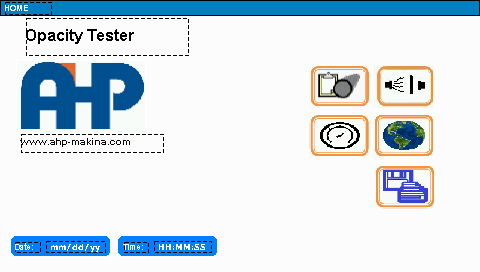
HMI Main Screen
The HMI Main Screen provides quick access to the main operating, setup, and calibration functions of the device.
- Language: Opens the language selection page to change the HMI display language.
- Parameters: Opens the parameter settings page for entering and adjusting the required device and test parameters.
- Calibration: Opens the calibration page for calibration and adjustment of the device measurement system.
- Save: Saves the entered parameters and settings in the device memory.
- Measurement: Opens the measurement screen for performing the test and monitoring the measured values.
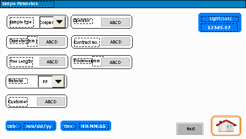
Test Specimen Parameters
This screen is used to enter the required information and parameters of the specimen before starting the test.
The operator must enter the specimen data according to the actual sample being tested. The entered parameters are stored together with the measurement results and included in the test report for specimen identification and traceability.
Sample Name
Enter the name or identification of the test specimen. This information is used to identify the sample in the saved test report.
Sample Code
Enter the identification or reference code assigned to the specimen. This allows the test result to be linked to a specific sample, batch, or production lot.
Width
Enter the measured width of the test specimen. The value should correspond to the actual specimen dimensions used for the test.
Thickness
Enter the measured thickness of the test specimen. The actual measured thickness should be entered before starting the test.
Length
Enter the required specimen length or relevant test length according to the test method being used.
Operator
Enter the name or identification of the operator performing the test. This information will be stored in the test report.
Note
Enter any additional information or comments related to the specimen or test conditions, if required.
After entering the required specimen parameters, proceed to the Measurement Screen to perform the test. The specimen information entered on this page will be saved together with the corresponding test results.
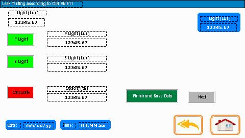
Measurement Screen
This screen is used to measure the light transmitted through the test specimen and calculate the Light Transmittance (%).
The measurement must be performed in the following sequence:
1. F LIGHT – Reference Light Measurement
Before placing the specimen in the measurement position, press the F LIGHT button.
The device measures and stores the light intensity without the specimen. This value is used as the reference light intensity for the calculation.
Important: Make sure that no specimen is present in the light path during this measurement.
2. S LIGHT – Sample Light Measurement
Place the test specimen in the correct measurement position and then press the S LIGHT button.
The device measures and stores the light intensity transmitted through the specimen.
3. CALCULATE – Light Transmittance Calculation
After both F LIGHT and S LIGHT values have been recorded, press the CALCULATE button.
The device automatically calculates the percentage of light transmitted through the specimen based on the reference and sample light measurements.
The calculated Light Transmittance (%) is then displayed on the HMI screen.
Measurement Sequence
No Specimen → Press F LIGHT → Insert Specimen → Press S LIGHT → Press CALCULATE → Light Transmittance (%)
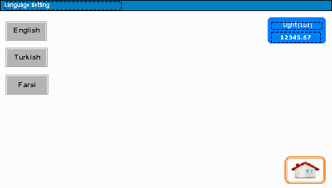
Language Selection Screen
This screen is used to select the operating language of the HMI.
Press the button corresponding to the desired language. After selection, the HMI menus, operating screens, parameters, and messages will be displayed in the selected language.
Language Selection
Select the required language by pressing the corresponding language button on the screen.
Back
Press the Back button to return to the Main Screen.
The selected language remains active during normal operation of the device.
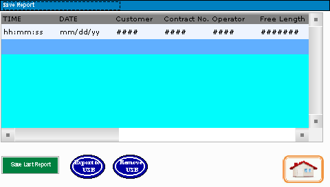
Data Storage and USB Export Screen
This screen is used to save the latest test report in the device memory and to export stored test data to a USB flash drive.
SAVE LAST REPORT
After completing a test, press SAVE LAST REPORT to save the latest test result in the internal memory of the device.
The saved report includes the test result together with the related specimen information and test parameters.
EXPORT USB
To export the stored test data:
- Connect a USB flash drive to the USB port of the device.
- Wait until the USB flash drive is recognized by the system.
- Press EXPORT USB.
- Wait until the data export process is completed.
The stored test data will be transferred to the connected USB flash drive.
REMOVE USB
Before physically removing the USB flash drive from the device, always press REMOVE USB.
Wait until the USB removal process is completed, and then disconnect the USB flash drive from the device.
Important: Do not remove the USB flash drive without first pressing REMOVE USB, as this may result in incomplete data transfer or corruption of the stored files.
Operating Sequence
Save Test Result:
Complete Test → Press SAVE LAST REPORT
Export to USB:
Connect USB → Press EXPORT USB → Wait for Export to Complete → Press REMOVE USB → Remove USB Flash Drive
25. Manufacturer Information
Manufacturer: AHP PLASTIK MAKINA
Equipment Name: Opacity Tester
Application: Determination of Opacity of Plastics Pipes and Fittings
Applicable Standard: ISO 7686:2005
Country of Origin: Türkiye