
6.4 Pipe Stiffness and Flattening:
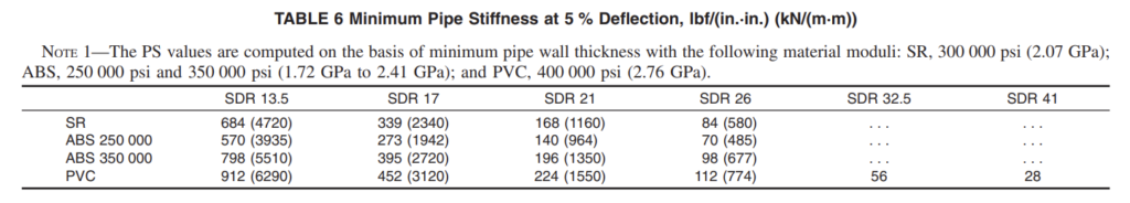
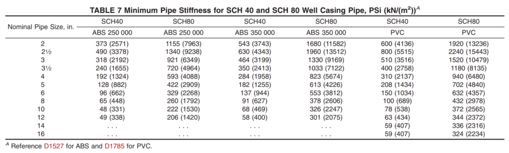
6.4.1 Well Casing Pipe—The well casing pipe shall have a pipe stiffness at 5 % deflection equal to that shown in Table 6 and Table 7 and shall deflect 60 % of the original diameter (flattening) without cracking, rupture, or other visible evidence of failure when tested in accordance with Test Method D2412. Three specimens shall be tested and all shall pass.
NOTE 5—This test is intended for use as a quality control test, not as a simulated service test.
6.4.2 Molded couplings shall have a pipe stiffness at 5 % deflection equal to that shown in Table 6 and Table 7 and shall deflect 15 % without cracking, rupture, or other visible evidence of failure when tested in accordance with Test Method D2412. Three specimens shall be tested and all shall pass.
6.5 Impact Resistance Classification—The impact resistance classification (IC) value for well casing pipe shall be selected from Table 8 by the manufacturer based on the measured average impact values determined in accordance with 7.5.
6.6 Tup Puncture Resistance—The well casing pipe and well casing couplings shall deflect 30 % (puncture resistance) without cracking, rupture, or other visible evidence of failure when tested in accordance with 7.6 (Note 7). Three specimens shall be tested and all shall pass.
7 Test Methods
7.1 Sampling—A sample of the well casing pipe and coupling sufficient to determine conformance with this specification shall be taken at random from each lot in accordance with Section 9 of Practice D1898.
7.2 Conditioning—Unless otherwise specified, condition the specimens prior to test at 72.4 °F ± 3.6 °F (23 °C ± 2 °C) and 50 % ± 10 % relative humidity for not less than 40 h in accordance with Procedure A of Practice D618. The manufacturer may use shorter conditioning time, but in case of
disagreement Procedure A of Practice D618 shall be used.
7.3 Test Conditions—Conduct tests in the standard laboratory atmosphere 73.4 °F ± 3.6 °F (23 °C ± 2 °C) and 50 ± 5 % relative humidity, unless otherwise specified in the test methods or in this specification.
7.5 Impact Classification (see Test Methods D2444)—
Determine the impact classification in accordance with Test Method D2444, using Tup B weighing 30 lb and Holder B. Select ten well casing pipe specimens of each size, with each specimen 6 in. ± 1⁄8 in. (150 mm ± 3 mm) in length. Condition the test specimens in a low-temperature environmental chamber, maintaining a test temperature of 32 °F to 35.6 °F (0.0 °C to 2.0°C) a minimum of 2 h or in a mixture of ice and water at 32 °F to 35.6°F for 1 h before testing and test immediately on removal. Test ten specimens in accordance with Test Method D2444; nine of the ten specimens shall be above the lower limit of the IC cell. Examine the results for conformance with 6.5.
7.6 Tup Puncture Resistance Test:
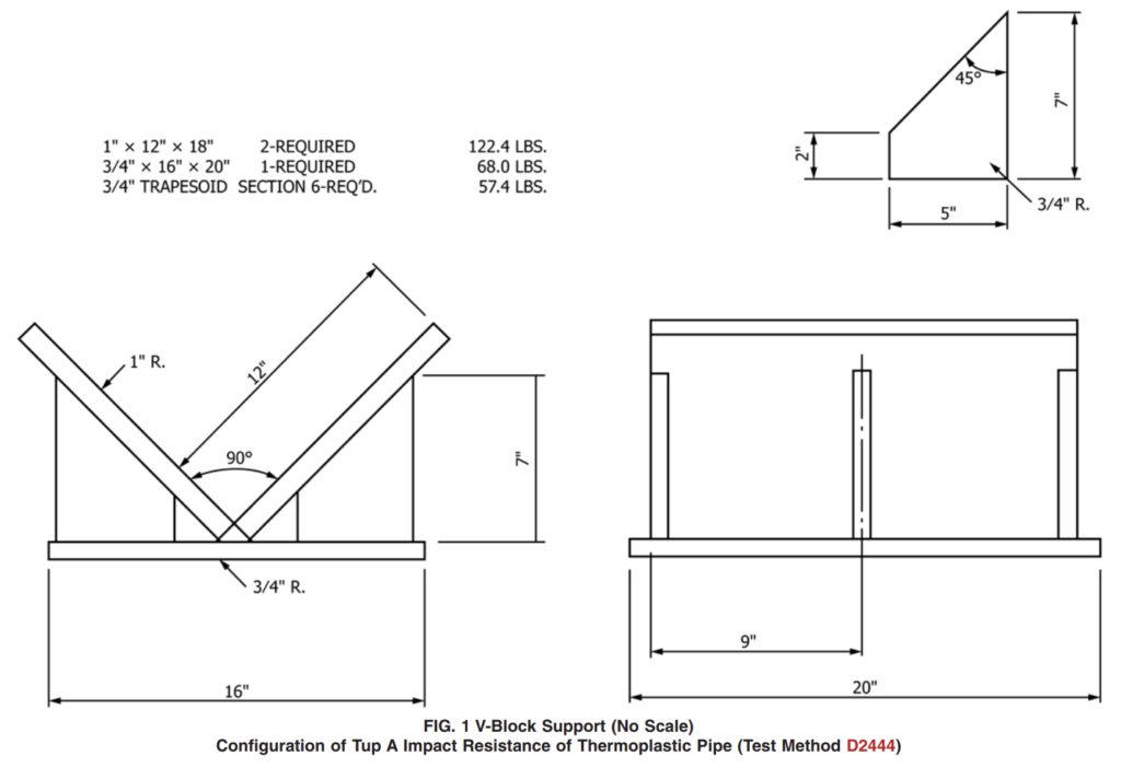
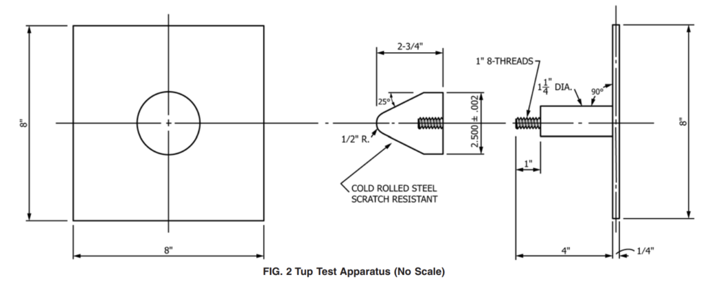
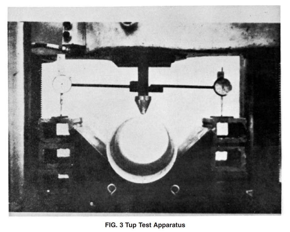
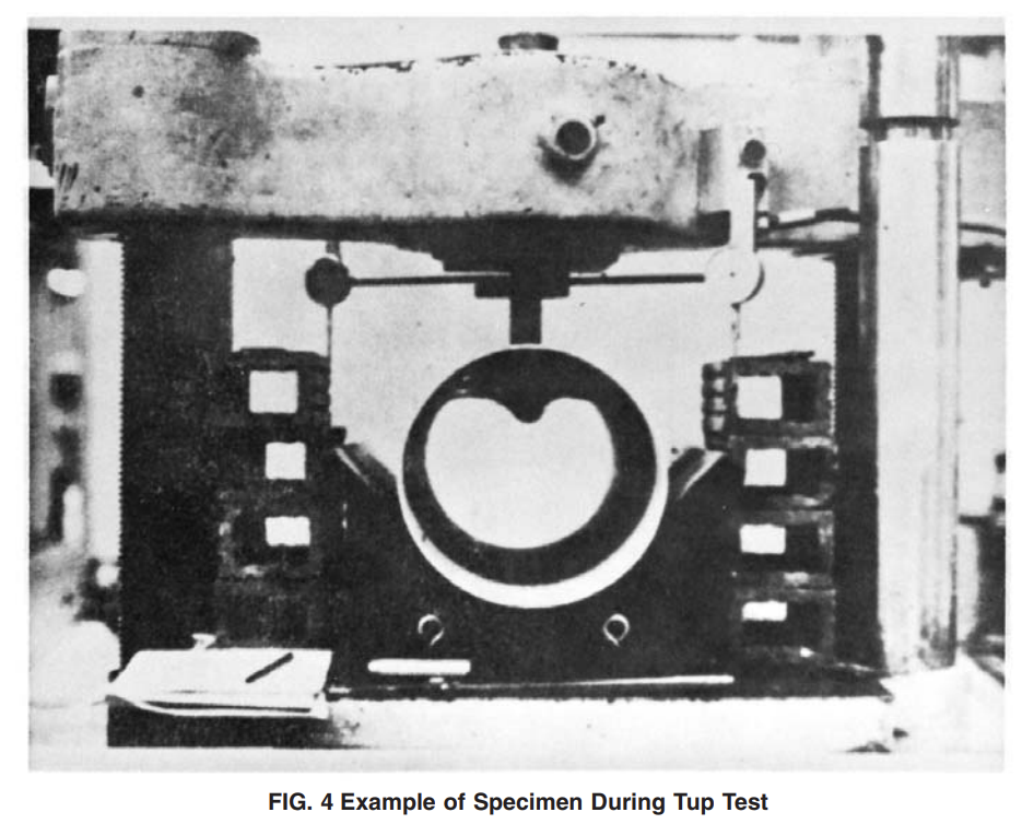
7.6.1 Procedure—Select three pipe specimens and three couplings. Determine whether the specimens are resistant to tup puncture at 30 % deflection by using the apparatus required for Test Method D2412 and Tup A as defined in Test Method D2444. The test method uses a constant-load rate instead of an impact load. The Vee-block base has been enlarged to accommodate larger specimens as seen in Fig. 1. Machine the base so that the two sides of the Vee form an angle of 90° ± 0.01°. Mount Tup A of Test Method D2444 on a square steel plate as shown in Fig. 2. Attach two Federal D01S dial gages to the square steel plate 180° apart as seen in Fig. 3 and Fig. 4. Measure the specimens to determine the point of minimum wall thickness. Place the pipe or coupling specimen of 6 in. ± 1⁄8 in. (150 mm ± 3 mm) in length in the universal load machine with the minimum wall of the specimen positioned directly under the nose of the tup. Place spacers between the dial gage stems and the base so that the deflection of the tup versus load can be measured. The speed of testing shall be 0.5 in. ± 0.02 in. (12.5 mm ± 0.5 mm)/min. Continue the test until the diameter is deflected 30 % of its original diameter (puncture resistance). Examine the test results for each specimen of pipe and coupling for conformance to Section 6.
NOTE 7—The tup puncture test for point load is derived from Test Methods D2412 and D2444, combined to achieve a meaningful design parameter for well casing pipe used in water well construction. There are many possibilities for a point load to be exerted on the well casing pipe. Perhaps the most significant of these is the stringing of a well casing pipe through a boulder field. The sides of the well hole are seldom smooth surfaces, but rather pieces of rock are embedded in the surrounding soil layers. When these rock particles come in contact with the well casing pipe, a point loading situation can develop. Natural earth movements can impose high stresses over a small area of well casing pipe surface. This type of localized load is an entirely different situation from a uniform load.
Visit Our Website and YouTube Channel for Test Equipment According to ASTM F480