4 Apparatus
4.1 Room, which can be controlled at a temperature of 23 ◦C ± 2 ◦C
4.2 Tensile-testing machine, capable of sustaining between its clamping jaws a constant speed of
5 mm/min ± 1 mm/min , and equipped with means for recording the consequent applied force, and a device to detect test piece failure.
4.3 Clamping device, equipped with bars fitting into traction holes machined in the test piece.
4.4 Measuring devices, capable of determining the width and thickness of the test piece to within
0,05 mm (see 7.1).
4.5 Template with the geometry of the test piece (see Figures 1 and 2), to mark the shape of the test piece to be machined.
5 Test pieces
5.1 Sampling
The pipes used to produce the test piece shall be obtained by sampling as specified in the product standard.
5.2 Preparation
5.2.1 General
The butt-fused PE pipe joints shall be prepared in accordance with the manufacturer’s instructions or the instructions specified in the relevant standards (e.g. ISO 11414).
For each test piece required, a strip shall be machined out along the longitudinal direction of the pipe, across the joint. The strip shall be further machined to prepare a test piece with dimensions conforming to:
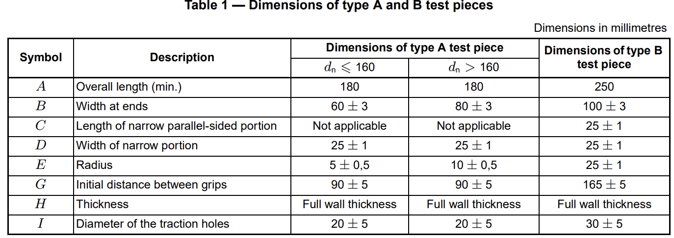
a) Table 1 and Figure 1 for pipes with wall thickness (e<25mm type A);
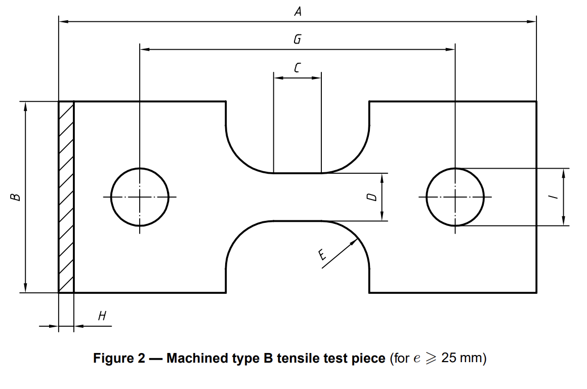
b) Table 1 and Figure 2 for pipes with wall thickness (e>=25mm type B);
using a template to ensure that the joint interface will be aligned with the cross-section of the centre of the waist of the test piece of type A or type B, as applicable.
The fusion beads may be removed.
5.2.2 Type A test piece
The dimensions and shape of the type A test piece shall conform to Figure 1 and Table 1.
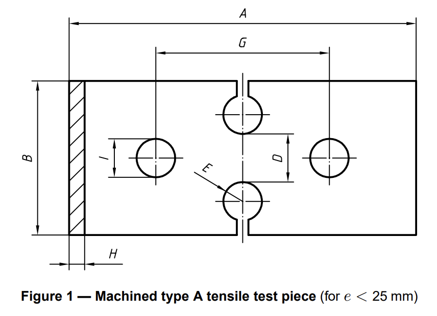
The “waist” of the test piece shall be formed by drilling or machining holes with their centres 35mm or 45mm apart, as applicable, so that the centrelines of the holes lie in the same plane as the joint interface, and then cutting towards the holes from the corresponding edge of the strip. The faces of the test piece waist shall be smooth. The finish of the remaining edges is not critical.
5.2.3 Type B test piece
The dimensions and shape of the type B test piece shall conform to Table 1 and Figure 2.
5.3 Number of test pieces
The number of test pieces shall depend upon the nominal outside diameter dnof the pipe, as given in Table 2.
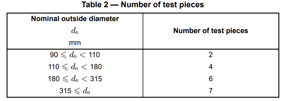
One test piece shall be taken at the position of maximum misalignment. The other test pieces shall be taken uniformly around the circumference of the joint.
6 Conditioning
Immediately prior to testing in accordance with clause 7, condition each test piece in air for a minimum of 6h at a temperature of 23+-2C , starting the period of conditioning at a time such that testing will not be carried out less than 24h after the butt fusion of the joint.
7 Procedure
7.1 Measure the thickness of the test piece as the thickness of the pipe wall and the width of the test piece as the distance between the two holes drilled at the joint ( D) for test pieces of type A (see Table 1 and Figure 1) or as the width of the narrow portion ( D) for test pieces of type B (see Table 1 and Figure 2).
7.2 Place the test piece in the clamping device of the tensile-testing machine, so that the direction of the force applied to the test piece is perpendicular to the butt-fusion joint.
7.3 Apply tension to the test piece with a cross-head speed of 5+-1mm/min.
7.4 Record the force applied during extension until complete failure of the test piece.
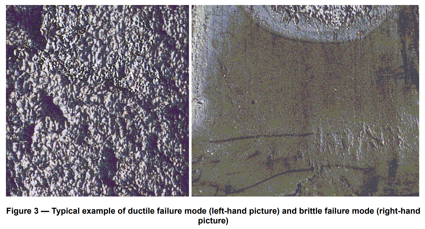
7.5 Record the maximum force applied (in newtons) and the type of failure as ductile or brittle, as characterized by the ductile and brittle failure modes shown in Figure 3. Only failures at the butt-fusion joint shall be taken into account.
7.6 Calculate the tensile strength as the maximum recorded tensile force (in newtons) divided by the crosssectional area of the centre of the test piece (i.e. width*thickness, as measured in accordance with 7.1, in square millimetres).