

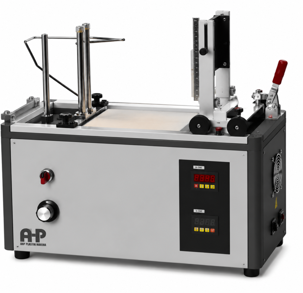
IEC 60695-2-11 defines the glow-wire flammability test method applied to end-products for fire-hazard assessment.
For the purpose of this test method, an end-product includes:
- complete electrotechnical equipment;
- subassemblies;
- components.
The purpose of the glow-wire test is to evaluate whether a part exposed to an abnormal thermal stress:
- resists ignition;
- limits the duration of burning if ignition occurs;
- and does not spread fire through flames, burning particles or glowing particles.
The test is particularly relevant to polymeric and insulating parts used in electrical and electrotechnical products where overheating of current-carrying parts, poor connections or abnormal electrical conditions may create a localized thermal ignition source.
IEC 60695-2-11 must be used together with IEC 60695-2-10, which defines the glow-wire apparatus and common test procedure.
1. Scope of IEC 60695-2-11
IEC 60695-2-11 specifies the detailed application of the glow-wire test to end-products.
The term end-product covers:
- electrotechnical equipment;
- subassemblies;
- individual components.
The test is therefore not primarily a raw-material classification test. Instead, it evaluates a component or product in a configuration representative of actual use. This distinction is important because the behaviour of a material may change when it is:
- molded into a specific geometry;
- attached to another component;
- placed near current-carrying parts;
- exposed to restricted airflow;
- or surrounded by other combustible materials.
2. Purpose of the Glow-Wire Test
The test is intended to simulate a localized thermal stress that may occur in electrical equipment under abnormal operating conditions. Examples of possible real-world thermal stresses include:
- overheated electrical connections;
- overloaded conductors;
- resistive heating;
- hot terminals;
- defective contacts;
- or nearby electrically heated parts.
The test determines whether the heated glow-wire causes ignition and, if ignition occurs, whether combustion is sufficiently limited. The test also evaluates whether burning or glowing particles can ignite surrounding material beneath the specimen.
3. Relationship with IEC 60695-2-10
IEC 60695-2-11 does not independently define the complete glow-wire apparatus.
Instead, it refers to: IEC 60695-2-10
for:
- apparatus construction;
- glow-wire geometry;
- test apparatus requirements;
- temperature measurement system;
- common test procedure;
- specified layer;
- and related general requirements.
Therefore, a complete IEC 60695-2-11 test system must satisfy both:
IEC 60695-2-10 – Apparatus and common test procedure
and
IEC 60695-2-11 – End-product flammability test method
This is a critical distinction when specifying or purchasing glow-wire test equipment.
4. Definition of Small Parts
The standard defines small parts based on the available surface area.
A part is considered a small part when:
- each surface lies entirely within a 15 mm diameter circle;
or
- part of the surface lies outside that 15 mm circle, but the remaining surface is such that an 8 mm diameter circle cannot be placed on it.
When evaluating the surface:
- projections;
- and holes not greater than 2 mm in their largest dimension
are disregarded. Small parts are important because the glow-wire method described in this standard is not intended for such parts.
5. Small Parts Are Not Tested by This Method
IEC 60695-2-11 states that the glow-wire test shall not be used for small parts as defined in the standard.
For such components, another test method may be required.
An example identified by the standard is the: needle-flame test
according to the relevant IEC method. This prevents inappropriate application of a relatively large glow-wire tip to very small components.
6. Test Specimen Selection
Whenever possible, the test specimen should be: the complete end-product
This is preferred because the complete product better reproduces actual operating conditions.
The specimen should be selected so that the test conditions are not significantly different from normal use with respect to:
- shape;
- ventilation;
- thermal stresses;
- flame behaviour;
- falling burning particles;
- falling glowing particles;
- surrounding components.
7. Testing When the Complete Product Cannot Be Used
If testing the complete end-product is impractical, the standard permits alternative specimen preparation unless the relevant product specification states otherwise.
The operator may:
Option A
Cut a section containing the part under investigation from the product.
Option B
Create an opening in the complete product so that the glow-wire can reach the intended test point.
Option C
Remove the part completely and test it separately. However, the relevant technical specification should define what may be removed or modified to gain access.
8. Why Specimen Modification Must Be Controlled
Modifying the product can alter the test result.
For example, creating an access aperture may affect:
- oxygen availability;
- local airflow;
- temperature distribution;
- ignition of surrounding materials;
- cooling of the glow-wire.
A small opening may restrict oxygen or alter heat transfer. An excessively large opening may introduce more oxygen than would normally be available in the actual product. Therefore, specimen preparation must preserve realistic test conditions as closely as possible.
9. Invalid Test Due to Extraneous Heating
A test is invalid if another part of the equipment becomes ignited by heat from the glow-wire and that ignition alters the thermal conditions at the test specimen.
This requirement is important because the test must evaluate the intended test point rather than an uncontrolled secondary ignition event.
10. Objective of the Test
The glow-wire test verifies that, under specified conditions:
Either
the glow-wire does not ignite the test specimen;
Or
if ignition occurs:
- combustion is limited in duration;
- fire does not spread excessively;
- flames do not cause unacceptable propagation;
- burning or glowing particles do not ignite the specified material below the specimen.
11. Additional Testing May Be Necessary
If the specimen produces flames during glow-wire application, those flames may reach other parts of the product. In such cases, additional testing using another ignition source may be necessary.
The standard specifically indicates that a needle-flame test may be appropriate for parts reached by the emitted flames. Therefore, successful completion of the glow-wire test does not automatically exclude the need for other fire-hazard tests.
12. Glow-Wire Apparatus
The apparatus requirements are specified in: IEC 60695-2-10
IEC 60695-2-11 therefore does not repeat detailed specifications for:
- glow-wire material;
- glow-wire loop dimensions;
- electrical heating circuit;
- force application;
- carriage mechanism;
- penetration control;
- thermocouple construction;
- temperature calibration;
- or flame measurement equipment.
Those requirements must be taken from IEC 60695-2-10. For a complete compliant testing system, both standards must therefore be considered.
13. Specified Layer Beneath the Test Specimen
To evaluate the possibility of fire spread caused by:
- burning particles;
- glowing particles;
- molten material;
a specified layer is placed beneath the specimen. The layer is defined in IEC 60695-2-10.
Alternatively, where appropriate, the actual material or components normally located beneath or around the tested part may be used. The purpose is to determine whether material released from the specimen can ignite its surroundings.
14. Position of the Specified Layer
Where the actual surrounding material or components are represented, the distance between:
- the test specimen;
- and the specified layer
shall correspond to the distance present in the real electrotechnical product. This ensures that fire propagation is evaluated under realistic geometric conditions.
15. Free-Standing Equipment
If the test specimen is a complete free-standing product, it is placed: in its normal position of use
on the specified layer. The layer shall extend: at least 100 mm beyond the base of the equipment in all directions.
This arrangement provides sufficient area to detect ignition from falling material.
16. Wall-Mounted Equipment
For complete wall-mounted equipment, the product is mounted in its normal position of use.
The specified layer is placed: 200 ± 5 mm below the equipment.
This geometry simulates the possible effect of falling burning or glowing particles in actual installation.
17. Test Severities
The glow-wire severity is defined by the test temperature.
Preferred test temperatures are:
| Test Temperature | Tolerance |
|---|---|
| 550 °C | ±10 K |
| 650 °C | ±10 K |
| 750 °C | ±10 K |
| 850 °C | ±15 K |
| 960 °C | ±15 K |
Other temperatures may be specified by the relevant product specification. The test temperature must therefore always be selected according to the requirements of the applicable product standard.
18. Significance of the Test Temperature
The glow-wire temperature represents the severity of the abnormal thermal stress.
In general:
- lower temperatures correspond to less severe thermal exposure;
- higher temperatures simulate more demanding ignition conditions.
The standard does not state that all products must be tested at the same temperature. Instead, the appropriate test severity depends on:
- product type;
- intended use;
- installation environment;
- whether equipment is attended or unattended;
- whether parts retain current-carrying components;
- consequences of ignition.
19. Guidance for Selecting the Test Temperature
The informative Annex A provides guidance for selecting a suitable temperature. The recommended severity should be chosen by considering:
- abnormal heat exposure;
- probability of ignition;
- potential for fire spread;
- consequences of failure.
The guidance is not a substitute for a mandatory product specification, but it provides a useful engineering basis.
20. Equipment for Attended Use
For equipment used under attended conditions, the guidance indicates: 650 °C
for insulation parts that:
- contact current-carrying components;
- retain current-carrying parts;
and also: 650 °C
for enclosures and covers not retaining current-carrying parts.
21. Unattended Equipment – Less Stringent Conditions
For equipment used unattended under less stringent operating conditions, the suggested severity is: 750 °C
for both:
- parts associated with current-carrying components;
- enclosures and covers.
22. Attended Equipment Under More Stringent Conditions
For attended equipment operating under more demanding conditions, the recommended guidance value is: 750 °C
for both categories of insulating parts.
23. Continuously Loaded Unattended Equipment
For unattended equipment that remains continuously loaded, the guidance recommends: 850 °C
for:
- insulating parts associated with current-carrying parts;
- enclosures and covers.
24. Continuously Loaded Unattended Equipment Under More Stringent Conditions
For continuously loaded unattended equipment exposed to more stringent conditions, the recommended severity increases to: 960 °C
for both categories.
25. Fixed Accessories in Installations
For fixed installation accessories, the guidance indicates:
Parts in Contact with or Retaining Current-Carrying Parts
750 °C
Enclosures and Covers Not Retaining Current-Carrying Parts
650 °C
26. Equipment Near the Central Supply Point of a Building
For equipment used near the central supply point of a building, the guidance indicates:
Parts Associated with Current-Carrying Parts
960 °C
Other Enclosures and Covers
750 °C
27. Minimum Resistance to Ignition and Fire Spread
Where the objective is to establish a minimum resistance to ignition or fire spread for parts contributing to a fire hazard but not otherwise tested, the guidance indicates: 550 °C
for both categories. This temperature is intended to eliminate highly combustible materials at a basic level of fire-hazard assessment.
28. Temperature Measurement System Verification
Verification of the glow-wire temperature measuring system shall be performed according to: IEC 60695-2-10
IEC 60695-2-11 does not independently define the temperature calibration procedure. This verification must be completed to ensure that the indicated glow-wire temperature corresponds to the required test severity.
29. Conditioning of Test Specimens
Unless otherwise specified by the relevant product specification, the:
- test specimen;
- specified layer
shall be conditioned for: 24 hours
in an atmosphere of:
Temperature
15 °C to 35 °C
Relative Humidity
45 % to 75 %
Conditioning is important because moisture content and ambient exposure can significantly affect ignition and flame behaviour of polymeric materials.
30. Initial Examination
Before the test, the specimen shall be:
visually examined
Where required by the applicable specification, relevant:
- mechanical parameters;
- electrical parameters
shall also be measured. This provides baseline information for evaluating any changes caused by the test.
31. General Test Procedure
The common glow-wire application procedure is specified in IEC 60695-2-10.
IEC 60695-2-11 adds requirements specific to end-products. The test specimen must be arranged so that the glow-wire tip is applied to the location most representative of abnormal thermal stress during normal use.
32. Selection of the Glow-Wire Application Point
The glow-wire shall be applied to the part of the specimen surface that is:
most likely to experience thermal stress during normal use.
Examples may include areas near:
- current-carrying parts;
- electrical terminals;
- contacts;
- connection points;
- resistive components;
- heat-generating electrical elements.
The applicable product standard should identify the intended test point where possible.
33. Glow-Wire Orientation
The glow-wire shall be maintained:
as close to horizontal as practicable.
This requirement provides consistent application geometry.
34. Multiple Test Points on the Same Specimen
If several locations must be tested on one specimen, previous testing shall not influence subsequent results. The operator must ensure that:
- prior burning;
- heat damage;
- deformation;
- carbonization;
- mechanical damage
does not affect later test points. If such influence cannot be excluded, separate specimens may be necessary according to the applicable specification.
35. Test Point When Thermal Stress Area Is Not Defined
If the product specification does not clearly define the area exposed to abnormal thermal stress, the glow-wire tip is applied:
where the section is thinnest
but preferably:
not less than 15 mm from the upper edge of the specimen.
This requirement provides a consistent default approach for selecting the most vulnerable region.
36. Specimen Clamping
The specimen shall be fixed to the test apparatus without introducing excessive internal mechanical stress. Improper clamping could:
- deform the specimen;
- create stress concentrations;
- alter thermal contact;
- influence cracking or melting;
- affect ignition behaviour.
Therefore, the fixture should support the specimen while maintaining a representative mechanical condition.
37. Number of Test Specimens
Unless otherwise specified by the relevant product specification:
the test is performed on one specimen.
Product standards may require:
- more than one specimen;
- multiple locations;
- repeated tests;
- additional conditioning.
38. Observation Period
The specimen is observed:
During glow-wire application
and for:
a further 30 seconds
afterwards.
During this entire period, the operator shall observe:
- the test specimen;
- parts surrounding the specimen;
- the specified layer underneath.
39. Ignition Time – ti
The parameter: ti
is the time interval from the beginning of glow-wire application until:
- the test specimen ignites;
- or the specified layer below it ignites.
This ignition delay provides useful information about the resistance of the assembly to thermal ignition.
40. Extinguishing Time – te
The parameter: te
is measured from the beginning of glow-wire application until the flames extinguish.
The extinction may occur:
- while the glow-wire is still applied;
- or after the glow-wire has been removed.
This parameter is central to the pass/fail evaluation.
41. Maximum Flame Height
The maximum flame height shall be observed and reported.
The value is:
rounded upward to the next 5 mm.
A brief initial flame peak occurring during ignition may be disregarded where it lasts approximately:
1 second.
This avoids assigning excessive significance to a transient ignition flash.
42. Definition of Flame Height
Flame height is defined as the vertical distance between:
- the upper edge of the glow-wire while applied to the specimen;
- and the visible tip of the flame.
Observation should be made in:
subdued light
to improve visual identification of the flame tip.
43. Material Withdrawn with the Glow-Wire
In some tests, flaming material may adhere to the glow-wire and be physically withdrawn when the glow-wire is removed. If the specimen passes the test mainly because the flaming material is removed together with the glow-wire:
this condition shall be reported.
This provides transparency regarding the actual reason why continued burning did not occur.
44. Ignition of the Specified Layer
Any ignition of the material placed below the specimen shall be recorded. This is essential because the glow-wire test evaluates not only self-extinguishing behaviour but also:
secondary fire propagation due to falling particles.
45. Mechanical and Electrical Measurements
Where required by the relevant product specification, mechanical and electrical parameters shall also be measured after testing. Examples may include parameters defined by the product standard.
IEC 60695-2-11 itself does not define universal mechanical or electrical acceptance values.
46. Pass/Fail Evaluation
Unless the relevant product specification defines different criteria, the specimen passes the glow-wire test if:
Condition 1
There is:
no flaming and no glowing
during the relevant test period;
Or
if flaming or glowing occurs, all required conditions below are satisfied.
47. Extinction Criterion
If flaming or glowing occurs, it shall extinguish within:
30 seconds after removal of the glow-wire.
In the terminology of the standard:
te ≤ ta + 30 s
where:
- ta is the duration of glow-wire application;
- te is the time from beginning of application until flame extinction.
48. Wrapping Tissue Criterion
Where the specified layer consists of wrapping tissue:
the wrapping tissue shall not ignite.
Therefore, a specimen that self-extinguishes may still fail if falling burning material ignites the specified layer underneath.
49. Practical Pass/Fail Logic
In simplified terms:
PASS
if:
No flame / no glow
OR
Flame or glow extinguishes within 30 s after glow-wire removal AND the specified wrapping tissue does not ignite.
FAIL
if:
- combustion continues beyond the permitted time;
- or the specified wrapping tissue ignites.
The relevant product standard may impose additional requirements.
50. Importance of the Relevant Product Specification
IEC 60695-2-11 repeatedly refers to the:
relevant specification
because the exact test conditions depend on the type of product being evaluated. The product specification should define several important parameters.
51. Information to Be Specified by the Product Standard
The relevant specification should define:
1. Test Specimen
Type and description of the specimen.
2. Specimen Preparation
How the product or component is prepared for testing.
3. Conditioning
Any conditioning different from the default requirement.
4. Number of Specimens
The number of specimens required.
5. Surface and Application Point
Which surface shall be tested and the exact glow-wire contact point.
6. Specified Layer
The material below the specimen used to evaluate flaming particles.
7. Test Temperature
The required glow-wire severity.
8. Multiple Test Points
Whether several locations must be tested on one specimen.
9. Additional Acceptance Criteria
Whether the standard pass/fail requirements are sufficient or whether additional criteria are required for:
- ti;
- te;
- flame height.
10. Mechanical/Electrical Parameters
Any functional or electrical measurements required before or after the test.
52. Complete Test Sequence
A practical IEC 60695-2-11 test sequence can be summarized as follows.
Step 1 – Identify Applicable Product Specification
Determine:
- required glow-wire temperature;
- test location;
- specimen configuration;
- acceptance criteria.
Step 2 – Select the Specimen
Use the complete end-product where possible.
If necessary, prepare a representative section or component.
Step 3 – Verify That the Part Is Not a Small Part
Confirm that the specimen is suitable for glow-wire testing according to the dimensional definition.
Step 4 – Condition the Specimen
Unless otherwise specified:
24 h at 15–35 °C and 45–75 % RH.
Step 5 – Inspect the Specimen
Perform visual examination and any required initial electrical or mechanical measurements.
Step 6 – Prepare the Specified Layer
Position the required material beneath the specimen according to the product configuration.
Step 7 – Verify the Test Temperature
Confirm the glow-wire temperature measurement system according to IEC 60695-2-10.
Step 8 – Mount the Specimen
Avoid excessive mechanical stress.
Step 9 – Select the Application Point
Apply the glow-wire to the location expected to experience the greatest thermal stress.
Step 10 – Apply the Glow-Wire
Carry out the common application procedure according to IEC 60695-2-10.
Step 11 – Observe the Specimen
Monitor:
- ignition;
- glowing;
- flame;
- falling particles;
- surrounding components;
- specified layer.
Step 12 – Record ti
Record the time to ignition.
Step 13 – Record te
Record the time until flame extinction.
Step 14 – Record Flame Height
Round upward to the next 5 mm.
Step 15 – Observe for 30 s After Application
Continue observing the specimen and specified layer.
Step 16 – Evaluate the Result
Determine whether:
- flaming or glowing extinguishes within the allowed time;
- the specified layer remains unignited.
Step 17 – Record Required Functional Measurements
Perform any required electrical or mechanical measurements.
Step 18 – Issue the Test Report
Document all relevant test conditions and observations.
53. Essential Pre-Test Checklist
Before starting an IEC 60695-2-11 test, verify:
✓ Applicable product specification identified
✓ Correct test temperature selected
✓ Glow-wire apparatus compliant with IEC 60695-2-10
✓ Temperature measuring system verified
✓ Correct test specimen selected
✓ Specimen represents normal-use configuration
✓ Specimen is not excluded as a small part
✓ Specimen conditioned as required
✓ Correct test surface selected
✓ Correct point of application selected
✓ Specimen mounted without excessive stress
✓ Correct specified layer installed
✓ Correct specimen-to-layer distance established
✓ Surrounding components represented correctly
✓ Required initial measurements completed
✓ Observation timing system ready
✓ Flame-height observation possible
✓ Test operator prepared to record ti and te
54. Essential Parameters – Quick Reference
Standard: IEC 60695-2-11:2000
Test type: Glow-wire flammability test
Application: End-products
Products covered: Equipment, subassemblies and components
Apparatus reference: IEC 60695-2-10
Preferred Test Temperatures
550 °C ±10 K
650 °C ±10 K
750 °C ±10 K
850 °C ±15 K
960 °C ±15 K
Default Conditioning
24 h
Temperature: 15–35 °C
Relative humidity: 45–75 %
Wall-Mounted Equipment
Specified layer:
200 ± 5 mm below the equipment
Free-Standing Equipment
Specified layer extends:
≥100 mm outside the equipment base in all directions
Default Test Quantity
One specimen
unless otherwise specified.
Observation
During glow-wire application plus:
30 s afterwards
Default Extinction Requirement
te ≤ ta + 30 s
Specified Layer Requirement
No ignition of wrapping tissue
55. Engineering Interpretation of the Test
The glow-wire test should not be interpreted only as:
“Does the plastic catch fire?”
It evaluates a broader fire-hazard scenario.
The engineering logic is:
localized abnormal heating
↓
possible ignition of the component
↓
duration of flaming or glowing
↓
possible generation of burning particles
↓
possible ignition of surrounding materials
↓
potential fire propagation
This is why the test evaluates both:
the component itself
and:
the material located beneath it.
56. Difference Between End-Product Testing and Material Testing
An important point is that IEC 60695-2-11 is specifically intended for: end-products.
The performance of a raw polymer alone may not directly predict the behaviour of the finished product.
Actual fire behaviour can be affected by:
- wall thickness;
- geometry;
- ribs;
- openings;
- ventilation;
- metal inserts;
- nearby conductors;
- mounting conditions;
- thermal mass;
- orientation.
Therefore, testing the finished component provides information that cannot always be obtained from a raw-material classification alone.
57. Why the Test Point Matters
The glow-wire should be applied where abnormal heating is realistically expected. Testing an arbitrary or excessively thick area can produce a result that is not representative of the actual fire risk.
For this reason, the standard prioritizes:
the area likely to experience thermal stress in normal use.
Where that location is not defined, the thinnest section is used as a practical default.
58. Why the Specified Layer Matters
A product can appear to self-extinguish yet still create a serious fire hazard if:
- molten plastic;
- burning droplets;
- glowing fragments
fall onto combustible material. The specified layer therefore evaluates:
secondary ignition and fire propagation.
This is one of the most important safety principles of the glow-wire end-product test.
59. Practical Test Report Contents
A detailed test report should include at least:
- test standard;
- applicable product specification;
- product identification;
- specimen description;
- specimen preparation;
- conditioning;
- number of specimens;
- selected test surface;
- glow-wire application point;
- test temperature;
- specified layer;
- specimen-to-layer geometry;
- ignition occurrence;
- ignition time, ti;
- extinction time, te;
- maximum flame height;
- ignition of specified layer;
- unusual behaviour;
- material removed with glow-wire;
- additional electrical/mechanical measurements;
- final pass/fail evaluation.
The exact reporting format may be supplemented by the applicable product specification.
60. Conclusion
IEC 60695-2-11 provides a structured method for assessing the response of electrotechnical end-products to abnormal localized heating. A valid test requires more than simply heating a plastic component.
The complete evaluation includes:
Representative specimen selection
↓
Correct conditioning
↓
Correct glow-wire severity
↓
Representative application point
↓
Controlled application according to IEC 60695-2-10
↓
Observation of ignition and flame behaviour
↓
Evaluation of burning and glowing particles
↓
Assessment of the specified layer
↓
Application of defined pass/fail criteria
The fundamental acceptance principle is:
The specimen shall either not ignite or glow, or any flaming/glowing shall extinguish within 30 s after removal of the glow-wire, without ignition of the specified wrapping-tissue layer, unless the relevant product specification establishes different criteria.