
8.1 Test Criteria
8.1.1 Materials shall be classified V-0, V-1, or V-2 on the basis of results obtained on small bar specimens
when tested as described in (8.2.1 – 8.5.6).
8.1.2 Some materials, due to their thinness, distort, shrink, or are consumed up to the holding clamp
when subjected to this test. These materials may be tested in accordance with the test procedure in Thin
Material Burning Test; VTM-0, VTM-1, VTM-2… Section 11, provided specimens can be properly formed.
8.1.3 Table 8.1 specifies the material classifications.

8.1.4 If only one specimen from a set of five specimens does not comply with the requirements, another
set of five specimens is to be tested. In the case of the total number of seconds of flaming, an additional
set of five specimens is to be tested if the totals are in the range of 51 – 55 seconds for V-0 and 251 –
255 seconds for V-1 and V-2. All specimens from this second set shall comply with the appropriate
requirements in order for the material in that thickness to be classified V-0, V-1, or V-2.
8.1.5 Type 66 nylon materials classed V-2 shall have a relative viscosity (RV) of less than 120 in the
supplied form, as determined by the method specified in 8.1.6, or if the relative viscosity is 120 or greater,
the relative viscosity of the molded specimen shall not be less than 70 percent of the relative viscosity in
the supplied form.
8.1.6 The relative viscosity is to be determined by the solution method in ASTM D789, using either a pipet
or Brookfield viscometer.
8.2 Test apparatus
8.2.1 See 5.1, 5.2, 5.5 – 5.8, 5.10, 5.12 – 5.15, 5.20 and 5.21.
5 Apparatus
5.1 Laboratory Fume Hood – having an inside volume of at least 0.5 m3, is to be used when testing the
specimens. The chamber is to permit observation and is to be draft free while permitting normal thermal
circulation of air past the specimen during burning. For safety and convenience, it is desirable that
thisenclosure (which can be completely closed) be fitted with an evacuation device, such as an exhaust
fan, to remove products of combustion which may be toxic. However, it is important to note that the device
shall be turned off during the actual test and started again immediately after the test to remove the
products of combustion.
Note: The amount of oxygen available to support combustion is important for the conduct of these flame
tests. For tests conducted by this method when burning times are prolonged, chamber sizes less than 1
m3 do not consistently provide accurate results.
5.2 Laboratory Burner – A laboratory type burner having a tube with a length of 100 ±10 mm and an
inside diameter of 9.5 ±0.3 mm. The barrel is not to be equipped with an end attachment, such as a
stabilizer. The burner shall be in compliance with ASTM D5025.
5.5 Ring Stands – Laboratory ring stands with clamps or the equivalent, for horizontal or vertical
positioning of the specimen and/or the wire gauze. Laboratory ring stands with clamps adjustable to the
desired angles and heights, or a support gauze holder constructed from aluminum or steel, or equivalent
equipment.
5.6 Timing Devices – Accurate to 0.5 second.
5.7 Measuring Scale – Graduated in mm.
5.8 Gas Supply A supply of technical grade methane gas (min. 98 percent pure) with regulator and meter
for uniform gas flow.
5.10 Conditioning Room or Chamber – Capable of being maintained at 23 ±2°C and a relative humidity
of 50 ±5 percent.
5.12 Micrometer – Capable of being read to 0.01 mm.
5.13 Cotton – A supply of absorbent 100 percent cotton.
5.14 Desiccator – A desiccator containing anhydrous calcium chloride, or other drying agent, maintained
at a relative humidity not exceeding 20 percent at 23 ±2°C.
5.15 Conditioning Oven – A full draft air-circulating oven, minimum of 5 air changes per hour, capable of
being maintained at 70 ±1°C.
5.20 Manometer/Pressure Gage – A gage capable of measuring to 200 mm of water, with increments of
5 mm.
5.21 Flow Meter – A rotameter calibrated in accordance with the Practice of Rotameter Calibration, D
3195, with correlation curves appropriate for the gas, or a mass flow meter with ±2 percent accuracy
8.3 Test specimens
8.3.1 All specimens are to be cut from sheet material, or are to be cast or injection, compression, transfer
or pultrusion molded to the necessary form. After any cutting operation, care is to be taken to remove all
dust and any particles from the surface; cut edges are to have a smooth finish. Fabrication of test
specimens shall be in accordance with current ASTM Practices.
8.3.2 Standard bar specimens are to be 125 ±5 mm long by 13.0 ±0.5 mm wide, and provided in the
minimum and maximum thicknesses. The maximum thickness is not to exceed 13 mm. Specimens in
intermediate thicknesses are also to be provided and shall be tested if the results obtained on the
minimum or maximum thickness indicate inconsistent test results. Intermediate thicknesses are not to
exceed increments of 3.2 mm. Also, the edges are to be smooth, and the radius on the corners is not to
exceed 1.3 mm.
8.3.3 Material Ranges – If a material is to be considered in a range of colors, densities, melt flows, or
reinforcement, specimens representing these ranges are also to be provided.
8.3.4 Specimens in the natural and in the most heavily pigmented light and dark colors are to be provided
and considered representative of the color range, if the test results are essentially the same. In addition,
a set of specimens is to be provided in the heaviest organic pigment loading, unless the most heavily
pigmented light and dark colors include the highest organic pigment level. When certain color pigments
(for example, red, yellow, or the like) are known to affect flammability characteristics, they are also to be
provided.
8.3.4 revised June 10, 1997
8.3.5 Specimens in the extremes of the densities, melt flows and reinforcement contents are to be
provided and considered representative of the range, if the test results are essentially the same. If the
burning characteristics are not essentially the same for all specimens representing the range, evaluation
is to be limited only to the materials in the densities, melt flows, and reinforcement contents tested, or
additional specimens in intermediate densities, melt flows, and reinforcement contents are to be provided
for tests.
8.4 Conditioning
8.4.1 Two sets of five specimens are to be preconditioned as in 6.1.
8.4.2 Two sets of five specimens each are to be preconditioned as in 6.2.
Exception: As an alternative, industrial laminates are to be conditioned for 24 hours at 125 ±1°C.
8.5 Procedure
8.5.1 Clamp the specimen from the upper 6 mm of the specimen, with the longitudinal axis vertical, so
that the lower end of the specimen is 300 ±10 mm above a horizontal layer of not more than 0.08 g of
absorbent 100 percent cotton thinned to approximately 50 x 50 mm and a maximum thickness of 6 mm
(See Figure 8.1).
8.5.2 The methane gas supply to the burner shall be arranged as in Figure 7.3 and adjusted to produce
a gas flow rate of 105 ml/min with a back pressure less than 10 mm of water. See ASTM D 5207.
8.5.3 Adjust the burner to produce a blue flame 20 ±1 mm high. The flame is obtained by adjusting the
gas supply and air ports of the burner until a 20 ±1 mm yellow-tipped blue flame is produced. Increase
the air supply until the yellow tip just disappears. Measure the height of the flame again and readjust it if
necessary.
8.5.4 The test flame shall be calibrated in accordance with ASTM D 5207at least once a month and when
the gas supply is changed, test equipment is replaced, or when data is questioned.
8.5.4 revised July 10, 1998
8.5.5 Apply the flame centrally to the middle point of the bottom edge of the specimen so that the top of
the burner is 10 ±1 mm below that point of the lower end of the specimen, and maintain it at that distance
for 10 ±0.5 seconds, moving the burner as necessary in response to any changes in the length or position
of the specimen. If the specimen drips molten or flaming material during the flame application, tilt the
burner at an angle of up to 45 degrees and withdraw it just sufficiently from beneath the specimen to
prevent material from dropping into the barrel of the burner while maintaining the 10 ±1 mm spacing
between the center of the top of the burner and the remaining portion of the specimen, ignoring any strings
of molten material. After the application of the flame to the specimen for 10 ±0.5 seconds, immediately
withdraw the burner at a rate of approximately 300 mm/sec, to a distance at least 150 mm away from the
specimen and simultaneously commence measurement of the afterflame time t1 in seconds. Record t1.
8.5.6 As soon as afterflaming of the specimen ceases, even if the burner has not been withdrawn to the
full 150 mm distance from the specimen, immediately place the burner again under the specimen and
maintain the burner at a distance of 10 ±1 mm from the remaining portion of the specimen for an additional
10 ±0.5 seconds, while moving the burner clear of dropping material as necessary. After this application
of the flame to the specimen, immediately remove the burner at a rate of approximately 300 mm/sec to a
distance of at least 150 mm from the specimen and simultaneously commence measurement of the
afterflame time, t2, and the afterglow time, t3. Record t2 and t3.
Note 1: If it is difficult to visually distinguish between flaming and glowing, a small piece of cotton,
approximately 50 mm square as described in 5.13, is to be brought into contact with the area in question
by holding with tweezers. Ignition of the cotton will be indicative of flaming.
Note 2: If the test flame is extinguished during either flame application the test specimen is to be
disregarded and another specimen is to be tested. The only exception is in the case where the test flame
is extinguished as a direct result of out-gassing from the specimen. In this case, the burner shall be
reignited immediately and reapplied to the specimen so that the total time of application is 10 ±0.5
seconds.
8.6 Results
8.6.1 The following are to be observed and recorded:
a) Afterflame time after first flame application, t1.
b) Afterflame time after second flame application, t2.
c) Afterglow time after second flame application, t3.
d) Whether or not specimens burn up to the holding clamp.
e) Whether or not specimens drip flaming particles that ignited the cotton indicator

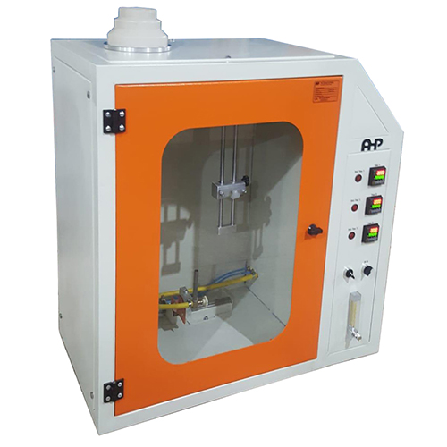
Flame Test Chamber UL94- 20 mm Vertical Burning Test; V-0, V-1, or V-2
- Chamber volume 0.5 m3
- Chamber includes exhaust fan
- Pneumatic application of flame
- Automatic timer run on flame application to the sample
- Door with glass window to see sample during test
- laboratory type burner having a tube with a length of 100 ±10 mm and an
inside diameter of 9.5 ±0.3 mm - Slides with rollers for easy positioning of the sample piece
- 3 Digital timer is included for measurement of 3 time records
- Graduated scale
- Desiccator is included
- Rotameter type flow meter and manometer is included
- Training video
- Other equipment as above-mentioned test method like gas supply, conditioning room, micrometer and conditioning oven will be quoted separately on customer request