
5.2 Vertical flame test
5.2.1 A specimen of the finished conduit shall be subjected to five 15-s applications of flame. the period between applications is 15 s. The specimen shall not be acceptable if it:
a) Continues to flame longer than 10 s, following the fifth application of the flame: or
b) Shows more than 25% of the indicator flag burned away or charred during, between, or after the five applications of the flame. Soot that can be removed with a cloth or the fingers and brown scorching shall be ignored: or
c) Emits flaming or glowing particles or flaming drops at any time that ignite the cotton on the burner, wedge, or floor of the enclosure. Flameless charring of the cotton shall be ignored.
The conduit need not be subjected to this test when it is made of a material that is classed 5VA or 5VB (small-scale flame test rating) in accordance with UL 94. CAN/CSA-C22 2 NO 0 17, or NMX-J-565-3-ANCE. and constructed of at least the same thickness as the material classed as 5VA or 5VB
5.2.2 This test shall be performed on unaged specimens in a 3-sided metal enclosure in an exhaust hood or cabinet. The metal enclosure shall be 305 mm (12 in) wide, 355 mm (14 in) deep, 610 mm (25 in) high,
and the top and front shall be open. A 457-mm (18 in) specimen cut from a length of finished conduit shall be secured with its longitudinal axis vertical in the center of the enclosure. A flat, horizontal layer of untreated surgical cotton 6 – 25 mm (1/4 – 1 in) thick shall cover the floor of the enclosure The upper surface of the cotton shall be 229 – 241 mm (9 – 9-1/2 in) below point B, which is the point at which the tip of the blue inner cone of the test flame touches the specimen (shown in Figure 2).
5 2.3 A burner conforming to ASTM 05025 or NMX-J-565-3-ANCE having a bore of 9.5 ±0.3 mm and a length of 100 ±10 mm from the top of the air-inlet openings to the top of the mixing tube, or an equivalent which meets the calibration of ASTM 05207 or NMX-J-565-3-ANCE shall be used While the barrel is vertical and the burner is well away from the specimen. the overall height of the flame shall be adjusted to approximately 100 – 125 mm (4 – 5 in). The blue inner cone shall be 38 mm (1-1/2 in) high and the temperature at its tip shall be 816°C (15OO°F) or higher as measured using a chromel-alumel (nickel-chromium and nickel-manganese-aluminum) thermocouple Without disturbing the adjustments for the height of the flame, the valve supplying gas to the burner flame and the separate valve supplying gas to any pilot flame shall be dosed.
5 2.4 A wedge (dimensions are specified in Figure 3) to which the base of the burner can be secured shall be provided for tilting the barrel 20° from the vertical while the longitudinal axis of the barrel remains in a vertical plane The burner shall be secured to the wedge and the assembly shall be placed in an adjustable support jig A layer of untreated surgical cotton 6 – 25 mm (1/4 – 1 in) thick shall be placed on the wedge and around the base of the burner. The jig shall be adjusted toward one side or the other of the enclosure to place the longitudinal axis of the barrel in the vertical plane that contains the longitudinal axis of the specimen. The plane shall be parallel to the sides of the enclosure. The jig shall also be adjusted toward the rear or front of the enclosure to position point A, which is the intersected of the Longitudinal axis of the barrel with the plane of the tip of the barrel, 38 mm (1-1/2 in) from point B at which the extended Longitudinal axis of the barrel meets the outer surface of the specimen. Point B is the point at which the tip of the blue inner cone touches the center of the front of the specimen.
5.2.5 In the absence of a gas pilot light on the burner. the support for the burner and wedge shall be arranged to enable the burner to be quickly removed from and precisely returned to the position described in 5.2.4 without disturbing the layer of cotton on the floor of the enclosure or the cotton on the wedge and around the base of the burner
5.2.6 A strip of unreinforced 94-g/m 2 or 60-lb kraft paper that is 0.13 mm (1/2 in) wide. approximately 5
mils or 0.1 mm thick. and is gummed-on one side shall be used to make an indicator flag. The gumming shall be moistened just to facilitate adhesion. With the gum toward the specimen, the strip shall be wrapped around the specimen once with its lower edge 254 mm (10 in) above B, the point at which the blue inner cone touches the specimen. The ends of the strip shall be pasted together evenly and trimmed to provide a flag that projects 19 mm (3/4 in) from the specimen toward the rear of the enclosure, with the Rag parallel to the sides of the enclosure (see Figure 2) The lower clamp or other support for the specimen shall be adjusted vertically to keep it from being any closer than 76 mm (3 in) to point B.
5.2.7 If the burner has a gas pilot light. the valve supplying gas to the pilot shall be opened and the pilot lit. If the burner does not have a gas pilot light. the burner shall be supported as indicated in 5.2.6 in a position away from the specimen and then lit. This operation and the remainder of the test shall be conducted under a forced-draft exhaust hood or cabinet operating to remove smoke and fumes. but not having drafts that affect the flame.
5.2.8 If the burner has a gas pilot light, the valve supplying gas to the burner shall be opened to apply the flame to the specimen automatically. This valve shall be held open for 15 s, closed for 15 s, and opened for 15 s and so forth for a total of five 15-s applications of the gas flame to the specimen. with 15 s between applications. If the burner does not have a gas pilot light, the burner shall be moved into position to apply the gas Raine to the specimen, kept there for 15 s, removed for 15 s, and so forth for a total of five 15-s applications of the gas flame to the specimen, with 15 s between applications The gas flame shall be reapplied to the specimen 15 s after the previous application. regardless of whether flaming of the specimen ceases of its own accord within 15 s of the previous application.
5.2 9 The gas used shall be either technical grade methane gas (min. 98 percent pure) supplied using a regulator and meter for uniform gas flow or natural gas having a heat content of approximately 37 ±1 MJ/m3 (993 ±27 Btu/ft3).


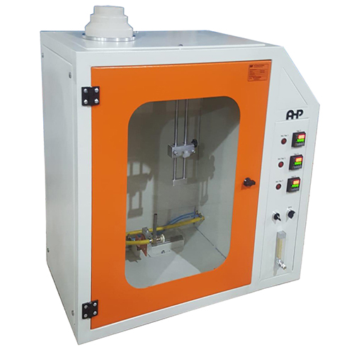
Flame Test Chamber According to UL 1660
- Equipped with digital timers
- Automatic flame application by pneumatic cylinder
- Timing control according to standard
- Metal enclosure 305 mm (12 in) wide, 355 mm (14 in) deep, 610 mm (25 in) high
- Burner conforming to ASTM 05025
- 20° tilting wedge included
- Gass pressure indicator
- Gas flow indicator