
4 Apparatus
4.1 Falling-weight testing machine, incorporating the following basic components {see figure 1).
4.1.1 Main frame, with guide rails or a guiding tube rigidly fixed in the vertical position, to accommodate a striker (4.1.2) and release it to fall vertically and freely. When calibrated, the speed of the striker at the moment of impact shall be not less than 95 % of the theoretical speed.
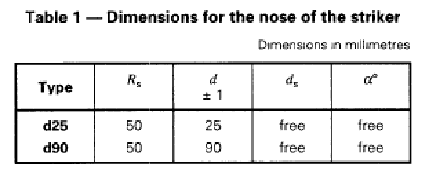
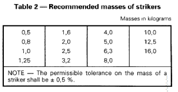
4.1.2 Striker, having a nose comprising all or part of a hemisphere, combined with a cylindrical stem at least 10 mm long, and having dimensions conforming to figure 2 and table 1, depending upon the mass of the striker. The mass of the striker, including any associated weights, shall be selected from the values given in table 2. Below the stem, the nose shall be of steel with a minimum wall thickness of 5 mm and the striking surface shall be free from visible imperfections such as scratches or dents which may influence the results.


Strikers with 0,5 kg and 0,8 kg mass shall have a type d25 nose. Strikers with greater masses shall have a
type d90 nose.
4.1.3 Rigid test support, consisting of a 120° V-block at least 200 mm long, positioned so that the
vertical projection of the point of impact of the falling striker is within 2,5 mm of the axis of the V-block (see figure 1).
4.1.4 Release mechanism, such that the striker can fall from a variable height which can be adjusted to any height up to at least 2 m, as measured from the top surface of the test piece, with an accuracy of ± 10 mm.
5 Test pieces
Test pieces of length 200 mm ± 10 mm shall be cut from pipe selected at random from the batch, or the production run from an extrudei’.
The cut ends shall be square to the axis of the pipe, clean and free from damage.
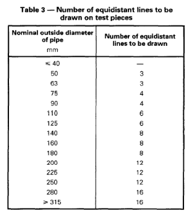
For pipes with outside diameters greater than 40 mm, a straight line shall be drawn along the length of each test piece at a random position. Further lines shall be drawn at equal distances around the pipe so that each test piece has the number of lines given in table 3. The number of blows required is given in clause 6. For pipes with outside diameters less than or equal to 40 mm, only one blow per test piece shall be made.


6 Sampling to confirm value of TIR on isolated batches
If the number of failures from a sample falls into
region A of figure 3 (for a TIR of less than or equal to 10 %), then reasonable confirmation is obtained that the batch has a TIR less than or equal to the specified level.
If the number of failures falls into region C, the batch can be judged to have a TIR greater than the specified value.
If the number of failures falls into region B, in general further test pieces should be taken so that a decision can be reached. However, attention is drawn to annex A for further details.
The decision shall be made by using the cumulative result of all the test pieces examined from the batch under consideration.
7 Conditioning
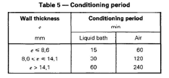
The test pieces shall be conditioned in a liquid bath or in air at the temperature of 0 °C ± 1 °C for at least the period given in table 5.
In case of dispute over the results, a liquid bath shall be used.
Test pieces with wall thickness up to 8,6 mm shall be tested within 10 s of their removal from air conditioning or within 20 s of their removal from liquid conditioning, as applicable.
Test pieces with wall thickness greater than 8,6 mm shall be tested within 20 s of their removal from air conditioning or within 30 s of their removal from liquid conditioning, as applicable.
If this interval is exceeded, the test piece shall be returned immediately to the conditioning unit for reconditioning for a minimum period of 5 min.
For pipes with smooth inside and outside surfaces, the wall thickness of the pipe to be tested shall be the total wall through the pipe section.
For pipes which are corrugated or ribbed externally, the wall thickness is the thickest wall of the pipe cross-section.
8 Procedure
The mass of the falling striker and the drop height appropriate to the pipe size shall be as specified in the appropriate product standard.
For pipes of outside diameter 40 mm or less, subject the test piece to a single blow.
For pipes of outside diameter greater than 40 mm, subject the test piece to a blow by allowing the striker to fall on one of the marked lines. If the test piece passes the test, rotate it in the V-block to the next marked line and again subject it to a blow from the falling hammer. striker, after reconditioning if necessary (see clause 7).
When the pitch of the corrugated or ribbed pipe is over 0,25 times the shaft diameter d, ensure that the test piece is struck on the top of the corrugation or the rib.
Continue this procedure until the test piece fails the test or until all marked lines have received one blow.
If required, carry out the test on subsequent test pieces, subjecting each one to a single blow.
9 Expression of results
The result shall be expressed as A, B or C for the
batch or the production run from an extruder, as follows:
A if the TIR is below 10 %;
B if no decision can be made on the basis of the number of test pieces used (however, see A.3):
C if the TIR is greater than 10 %.
NOTE 4 The number of failed test pieces, as compared to the total number of blows, should not be expressed as a percentage, to avoid confusion with the TIR of which the percentage is only an estimate.
For more info please check videos of our YouTube channel or ask in WhatsApp: