9.1 Test criteria
9.1.1 Material shall be classified 5VA or 5VB on the basis of test results obtained on small bar and plaque
specimens when tested as described in (9.2.1 – 9.6.5).
Exception: For materials that are submitted for a 5VB rating only (i.e., the manufacturer does not seek
the 5VA rating), plaque specimens do not need to be tested.
9.1.1 revised May 22, 2001
9.1.2 Materials classified 5VA or 5VB shall also comply with the requirements described in 8.1.1– 8.6.1
for materials classified V-0, V-1 and V-2.
9.1.2 revised July 29, 1997
9.1.3 Table 9.1 specifies the material classifications.
9.1.4 If only one specimen from a set of five bar specimens or one specimen from a set of three plaque
specimens does not comply with the requirements, another set of specimens are to be tested. All
specimens from this second set are to comply with the requirements in order for the material in that
thickness to be considered acceptable.
9.2 Test apparatus
9.2.1 See 5.1, 5.2, 5.4, 5.5, 5.6 – 5.8, 5.10, 5.12– 5.15, 5.20 and 5.21.
9.3 Test specimens
9.3.1 All specimens are to be cut from sheet material, or are to be cast or injection, compression, transfer
or pultrusion molded to the necessary form. After any cutting operation, care is to be taken to remove all
dust and any particles from the surface; cut edges are to have a smooth finish. Fabrication of test
specimens shall be in accordance with current ASTM Practices.
9.3.2 Bar specimens are to be 125 ±5 mm long by 13.0 ±0.5 mm wide, and provided in the minimum
thickness. Plaque specimens are to be 150 ±5 mm by 150 ±5 mm and provided in the minimum thickness.
Thicker specimens may also be provided and shall be tested if the results obtained on the minimum
thickness indicate inconsistent test results. The maximum thickness is not to exceed 13 mm. Edges are
to be smooth, and the radius on the corners is not to exceed 1.3 mm.
9.3.2 revised June 10, 1997
9.3.3 Material Ranges – If a material is to be considered in a range of colors, densities, melt flows, or
reinforcement, specimens representing these ranges are also to be provided.
9.3.4 Bar Specimens – Specimens in the natural (if used in this color) and in the most heavily pigmented
light and dark colors are to be provided and considered representative of the color range, if the test results
are essentially the same. In addition, a set of specimens is to be provided in the heaviest organic pigment
loading, unless the most heavily pigmented light and dark colors include the highest organic pigment level.
When certain color pigments (for example, red, yellow, or the like) are known to affect flammability
characteristics, they are also to be provided.
9.3.4 revised June 10, 1997
9.3.5 Plaque Specimens – Specimens in the natural or normally supplied color are to be provided, and
are to be considered representative of the color range.
9.3.6 Specimens in the extremes of the densities, melt flows and reinforcement contents are to be
provided and considered representative of the range, if the test results are essentially the same. If the
burning characteristics are not essentially the same for all specimens representing the range, evaluation
is to be limited only to the materials in the densities, melt flows, and reinforcement contents tested, or
additional specimens in intermediate densities, melt flows, and reinforcement contents are to be provided
for tests.
9.4 Conditioning
9.4.1 Two sets of five bar and three plaque specimens are to be preconditioned as in 6.1.
9.4.2 Two sets of five bar and three plaque specimens are to be preconditioned as in 6.2.
9.5 Bar specimens test procedure
9.5.1 Clamp the specimen from the upper 6 mm of the specimen, with the longitudinal axis vertical, so
that the lower end of the specimen is 300 ±10 mm above a horizontal layer of not more than 0.08 g of
absorbent cotton thinned to approximately 50 x 50 mm and a maximum thickness of 6 mm. See Figure
9.1.
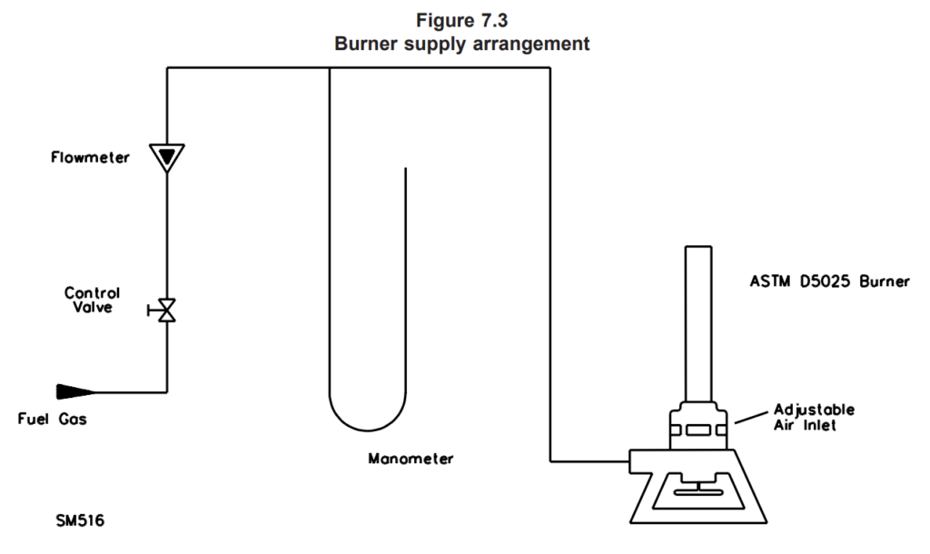
9.5.2 The methane gas supply to the burner shall be arranged as in Figure 7.3 and adjusted to produce
a gas flow rate of 965 ml/min with a back pressure of 125 ±25 mm water.
9.5.3 Place the burner remote from the specimen, ignite, and in a darkened room, adjust the gas flow.
With the burner in a vertical position, adjust the overall height of the flame to approximately 125 ±10 mm
and the height of the inner blue cone to 40 ±2 mm. Support the burner on the burner fixture so that the
burner tube is positioned at 20 ±5° from the vertical. The narrow edge of the specimen is to face the
burner. See Figure 9.1.
9.5.3 revised June 10, 1997
9.5.4 The test flame shall be calibrated in accordance with ASTM D 5207at least once a month and when
the gas supply is changed, test equipment is replaced, or when data is questioned.
9.5.4 revised July 10, 1998
9.5.5 The flame is then to be applied to one of the lower corners of the specimen at an angle of 20
degrees from the vertical, so that the tip of the blue cone just touches the specimen.
9.5.6 Apply the flame for 5 ±0.5 seconds and then remove for 5 ±0.5 seconds. Repeat the operation until
the specimen has been subjected to five applications of the test flame. If the specimen drips particles,
shrinks, or elongates during the test, adjust the burner so that the tip of the inner blue cone is in contact
with the major portion remaining on the specimen corner.
Note: When necessary, hand-hold the burner and fixture to complete the test.
9.5.6 revised June 10, 1997
9.5.7 After the fifth application of the test flame for each specimen, observe and record the following:
a) Afterflame time and afterglow time.
b) Whether or not flaming particles ignited the cotton.
9.6 Plaque specimens test procedure
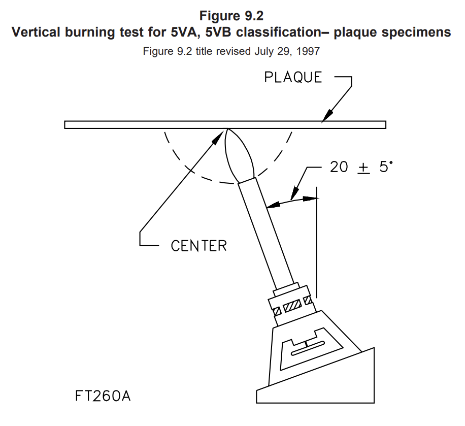
9.6.1 Support the plaque specimen by a clamp on the ring stand in the horizontal plane. See Figure 9.2.
9.6.2 Adjust and calibrate the burner as in 9.5.2 – 9.5.4.
9.6.3 The flame is then to be applied to the center of the bottom surface of the plaque at an angle of 20
±5° from the vertical, so that the tip of the blue cone just touches the specimen.
9.6.4 Apply the flame for 5 ±0.5 seconds and then remove for 5 ±0.5 seconds. Repeat the operation until
the plaque specimen has been subjected to five applications of the test flame. When necessary, to
complete the test, hand hold the burner and fixture so that the tip of the inner blue cone maintains contact
with the surface of the plaque.
9.6.4 revised June 10, 1997
9.6.5 After the fifth application of the test flame, and after all flaming or glowing combustion has ceased,
it is to be observed and recorded whether or not the flame penetrated (burned through) the plaque
material.

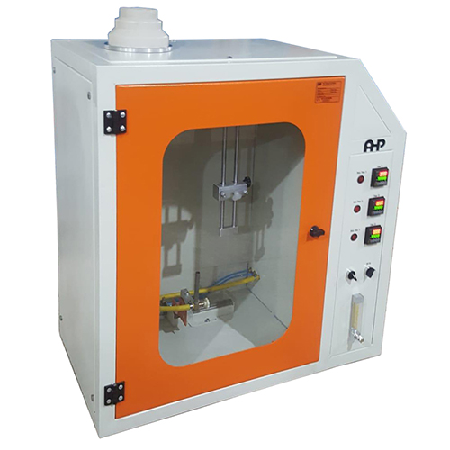
- The Horizontal Vertical Flame Chamber provides the most accurate means for determining the flammability of aircraft cabin and cargo compartment materials, liners and waste stowage compartment materials, and electric wire. Three digital timers make specimen event timing precise and convenient.
- The series of horizontal-vertical flame test apparatus are designed and manufactured according to the standard and related requirement of UL94 , IEC60695-11-2 , IEC60695-11-3 , IEC60695-11-4 , IEC60695-11-20
- It simulates the influence of early-stage flame when there is a fire around the electric and electronic products, so that to judge the igniting danger degree
- It is mainly used in plastic and other non-metallic material sample, solid material
- It is also applicable in the Horizontal, vertical flammability test of the relative combustion characteristic of foam plastics whose density is no-less than 250kg/m according to ISO845 test method.


