- Summary of Test Method
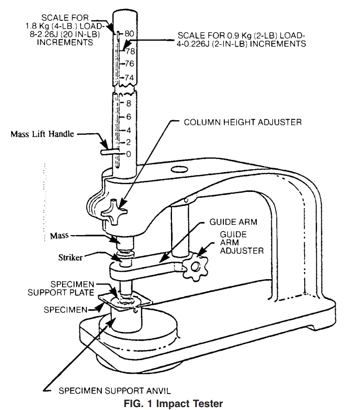
4.1 In this test method, a weight falls through a guide tube and impacts a striker resting on top of a supported specimen. The fixed weight is dropped from various heights (see Fig. 1).
4.2 The procedure determines the energy (mass 3 gravity 3 height) that will cause 50 % of the specimens tested to fail (mean-failure energy). 4.3 The technique used to determine mean-failure energy is commonly called the Bruceton Staircase Method, or the Up-and-Down Method (1).
3 Testing is concentrated near the mean, reducing the number of specimens required to obtain a reasonably precise estimate of the impact resistance. 4.4 This test method permits the use of different striker diameters and specimen support plate geometries to obtain different modes of failure, permit easier sampling, or test limited amounts of material. There is no known means for correlating the results of tests made by different methods or procedures.
- Apparatus
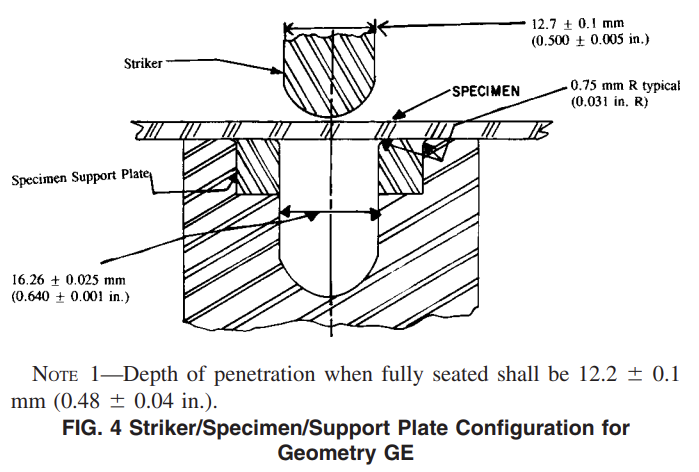
7.1 Testing Mechanism—The apparatus is shown in Fig. 1. Adapt the apparatus from Test Method D2794 for use in this test method or obtain the apparatus commercially. The apparatus shall consist of the following: suitable base to withstand the impact shock; steel-rod impact mass, weighing 0.9 kg (2 lb), 1.8 kg (4 lb), or 3.6 kg (8 lb); a hardened steel striker having a round nose with diameter described in 7.1.1 and 7.1.2 and Table 1; a slotted guide tube 1.0 m (40 in.) in length, in which the impact mass slides, having graduations in newtonmetres (inch-pound increments) ormultiples thereof. Use a bracket to hold the tube in a vertical position by attaching it to the base and also to hold the hand knob, which is a pivot arm alignment for the striker, about 50 mm (2 in.) under the tube. Mount this instrument firmly to a rigid table or bench. Round the top edge of the opening in each specimen-support plate to a 1.0 +- 0.2-mm (0.039 +- 0.008-in.) radius, except in Geometry GE which has a radius of 0.75 mm (0.031 in.).
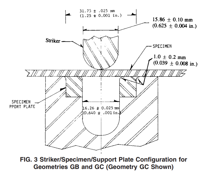
7.1.1 For Geometries GA, GB, and GC, the striker shall have a rounded nose with a diameter of 15.86 +- 0.10 mm (0.625 +- 0.004 in.).
7.1.2 For Geometries GD and GE the striker shall have a rounded nose with a diameter of 12.70 +- 0.1 mm (0.500 +- 0.004 in.).
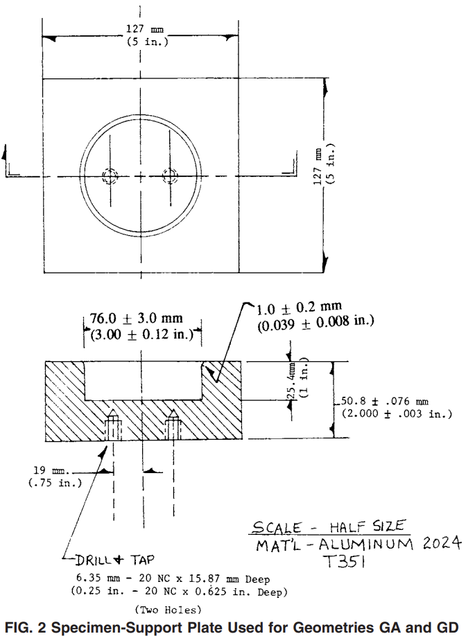
7.1.3 With Geometries GA and GD, a specimen-support plate with a hole 76.0 +- 3.0 mm (3.00 +- 0.12 in.) in diameter is mounted in the apparatus. A suggested design is given in Fig.2.
7.1.4 With Geometry GB, the specimen-support plate has a 31.75 +- 0.025-mm (1.25 +- 0.001-in.) diameter hole. This geometry can be achieved by removing the removable support ring on the standard Gardner instrument.
7.1.5 With Geometries GC and GE, the standard removable specimen-support plate, with a hole 16.26 +- 0.025 mm (0.640 +- 0.001 in.) in diameter, is mounted in the specimen support anvil (see Fig. 3 for Geometry GC and Fig. 4 for Geometry GE).
7.2 Supporting Base—In order to minimize the energy absorption, compression, and deflection of the support, affix the tester to a dense, solid block or base weighing a minimum of 400 lb (see Appendix X2). The main body of the block or base shall have maximum dimensions of 16 by 30 by 30 in. (height by width by depth). Place this block or base at a height suitable for ease of operation. It is not necessary to bolt blocks or bases of this weight to the floor. Alternatively, affix testers directly to the floor. Use of rubber mats either directly under the tester or supporting apparatus is prohibited. 7.2.1 Bolt supporting bases or tables lighter than 400 lb to a concrete floor. For each different material tested, make comparisons between mean failure energy data generated using this support and one where the tester is fixed directly to the concrete floor. If mean failure energy differences between two types of supports are found to be statistically nonsignificant, use of the lighter support shall be allowed.
7.3 Micrometer, for measurement of specimen thickness. Ensure that the accuracy is 1 % of the average thickness of the specimens used. See Test Methods D5947 for descriptions of suitable micrometers.