- Apparatus
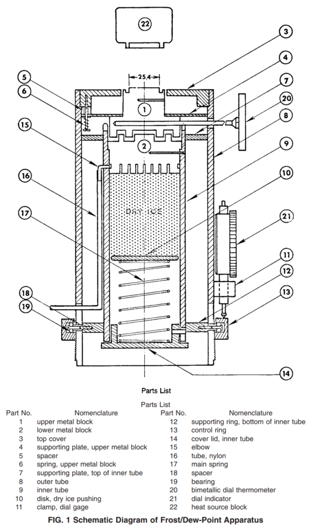
6.1 Test Apparatus (see Fig. 1), consisting of upper and lower cylindrical metal blocks with a thermocouple, bimetallic thermometer, or other suitable temperature sensors being inserted in the upper block; a control ring; and an insulated containment cylinder fitted with a retainer spring assembly. The two metal blocks are separated by a small air gap, the distance of which can be regulated by the control ring. The exposed flat circular surface of the upper block is 25 mm (1 in.) in diameter; has a ground or lapped finish; and, when placed in contact with the glass test specimen, forms the frost/dew point measuring surface. The lower block is chilled by a dry ice pack kept in contact with it by the retainer spring assembly, maintaining it at a temperature near to that of sublimating dry ice (−78°C (−109°F)). Because the solid metal blocks are highly conductive, the temperature of each is virtually uniform. Use of the control ring adjusts the air gap distance between the two blocks to give the desired thermal resistance across the air gap. The circular measuring surface of the upper block is thus readily adjusted to the desired temperature while in contact with the test specimen. The circular measuring surface diameter specified is suitable for frost/dew point measurement of glass up to 6.0 mm (1⁄4 in.) thick. 6.1.1 Upper and Lower Metal Blocks, aluminum alloy that may be anodized, conforming to the dimensions shown in Fig. Other parts of the apparatus may be fabricated from any
appropriate materials.
6.1.2 Calibrated Temperature-Measuring Device; such as a thermocouple, thermistor, or bimetallic thermometer; having a suitable range graduated in 1°C (2°F) or smaller units; and an accuracy of 60.5°C (61°F) over the full scale. A suggested calibration of the bimetallic thermometer is described in Appendix X1.
- Test Specimen
7.1 The specimen to be tested shall be representative of the units to be evaluated and capable of being positioned horizontally. - Conditioning
8.1 Prior to testing, condition the test specimen at a temperature of 24 +- 3°C (75 +- 5°F) for not less than 24 h.
- Procedure
9.1 Preparation of Apparatus:
9.1.1 Disassemble the apparatus by taking out the dry ice container and retainer spring assembly. Carefully clean the measuring surface with a soft cloth or paper. Do not scratch the measuring surface. Wipe and clean the apparatus thoroughly if any moisture is condensed on the surfaces and walls.
9.1.2 Assemble the dry ice container and turn the control ring so that the air gap distance between upper and lower metal blocks is about 13 mm (0.5 in.). Invert the apparatus onto a soft cloth.
9.1.3 Spray alcohol or acetone (Warning—Both alcohol and acetone are flammable.) on the fin of the dry ice container to ensure good contact with the dry ice. Compactly charge the container with the crushed or pulverized dry ice up to the “full” mark. Compress the dry ice with the spring assembly and lock the cover lid.
9.1.4 Return the apparatus to an upright position and secure it onto a horizontal surface. Allow sufficient time for the temperature of the lower metal block to approach that of the dry ice temperature.
9.2 Recharging of Apparatus:
9.2.1 During the test procedure, replenish the supply of dry ice whenever it becomes depleted by turning the apparatus upside down on a soft cloth, opening the cover lid, taking out the retainer spring assembly, and repeating steps 9.1.3 and 9.1.4.
9.3 Determination of Frost State and No-Frost State:
9.3.1 Charge the frost/dew point apparatus with dry ice as described in 9.1 or 9.2.
9.3.2 Clean both exterior surfaces of the specimen.
9.3.3 Place a piece of silver-colored aluminumized polyester film3 (highly reflective mirror surface, not thicker than 0.08 mm (0.003 in.) and 25 mm (1 in.) in diameter or 25 by 25 mm (1 by 1 in.) on the measuring surface by wetting both surfaces of the film with acetone or alcohol (Warning—See 9.1.3). Center the specimen on the apparatus. Examine the lower air space glass surface in the region where frost is to be deposited, to be aware of any dirt or other foreign particles that might be mistaken for frost. Note, however, that a small foreign particle on the lower air space glass surface may be helpful in focusing on the surface where the frost is to be deposited (see Fig. 2).
9.3.4 Slowly reduce the air gap distance between upper and lower metal blocks by turning the control ring while watching the temperature of the upper metal block
9.3.5 Bring the temperature of the upper metal block to the temperature to be checked for frost and stabilize it by fine adjustment of the control ring. Temperature fluctuation should not exceed +-1°C (2°F).
9.3.6 Maintain the stabilized temperature for a duration as follows:
9.3.7 Wipe off the condensation that may have occurred on the upper exterior surface of glass, or spray the upper surface with clear water.
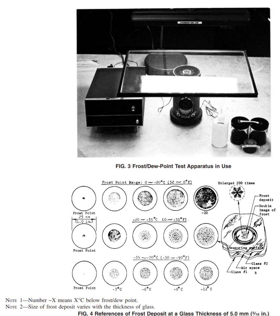
9.3.8 Examine the lower air space glass surface in contact with the measuring surface for frost. Illuminate this surface with a fluorescent desk lamp (two 15-W daylight bulbs), or equivalent for better detection of frost (see Fig. 3).
9.3.9 If a clearly visible frost deposit appears on the lower air space glass surface during or after the temperature stabilization period, the frost/dew point of the specimen is above this stabilized temperature (frost state) (see Fig. 4 for frost formation). Check for double image of the frost to assure that the frost lies on the lower air space glass surface (see Fig. 4 B). If the frost deposit is so small and faint that it cannot be distinguished from dirt or other foreign particles, lower the temperature of the measuring surface by 1°C (2°F) and hold this value for the duration given in 9.3.6. Reexamine the suspected particles. If the deposit is frost, its size or population will grow or get heavier.
9.3.9.1 Frost/dew point determination as described in 9.3.9 is difficult to observe on reflective glass. It is acceptable to lift the specimen off the tester and observe for frost by viewing the unit when held up to light. The observation shall be made within 5 s of removal from the tester.
9.3.10 If frost does not appear after the temperature stabilization period, the frost/dew point of the specimen is below this stabilized temperature (no-frost state).
9.3.11 To check at other temperatures, repeat the test procedure described in 9.3.3-9.3.10 for the temperatures desired.
9.4 Determination of Approximate Frost/Dew-Point Range:
9.4.1 Perform a series of measurements as described in 9.3 at successively lower temperatures until frost state is proven. Temperature intervals of 10°C (20°F) are preferable: for example, − 10°C (20°F), −20°C (0°F), −30°C (−20°F), − 40°C (−40°F), −50°C (−60°F), and − 60°C (−80°F) as described in 9.3. Other temperature levels can be checked as desired. The frost/dew point will be between the temperature at which frost appeared and the next higher temperature.
9.4.2 When the frost/dew-point range can be predicted by experience (newly fabricated specimen, and so forth), only the temperatures bracketing the predicted frost/dew point need be checked.
9.4.3 Estimate the frost/dew point of the specimen within the temperature range between frost and no-frost found in 9.4.1 by comparing the frost at the lower temperature limit (frost state) with the reference photograph (see Fig. 4) of similar temperature range.
9.5 Final Measurement of Frost/Dew Point:
9.5.1 Perform a series of no-frost, frost state measurements described in 9.4 by starting at a few degrees Celsius above the estimated frost/dew point. Lower the temperature by intervals of less than 2°C (3°F) (preferably 1°C (2°F)). If frost appears at the first starting temperature, re-estimate the frost/dew point using Fig. 4 and repeat the test.
9.5.2 The frost/dew point is the temperature at which visible frost first appears, or between this temperature and the next higher temperature that was checked.
9.5.3 Record the frost/dew point as the temperature of the upper metal block when the visible frost first appears.
9.5.4 For repeated measurements of frost/dew point on the same specimen, allow the frost to evaporate completely, or choose another spot at least 50 mm (2 in.) away from the previous measuring spot. Use a counterweight to balance the specimen. The heat source block (see Fig. 1, Part No. 22) may be warmed and placed in momentary contact with the upper metal block to raise its temperature before proceeding with a repeated measurement.

Frost/Dew Point Tester
- Principle of operation: The dew point tester is used with dry ice. The container is placed on the glass, and a thermometer shows the temperature changing at the point of contact with the glass. Note down the temperature as soon as moisture is observed on the other side of the glass pane.
- The higher the dew point, the greater the amount of humidity in the glass pane.
- Diameter of the exposed flat circular surface in upper block: Φ25,4mm ;
- Volume of dry ice container:Φ75×145mm ;
- Temperature ranges : from –10 °C to -50 °C ;
- Accuracy of digital thermocouple : 1 °C ;
- Thickness of glass: ≤6 mm.


