- Apparatus
5.1 For High Humidity Testing:
5.1.1 High-Humidity Test Chamber—A chamber of convenient dimensions capable of maintaining 60 +- 3°C (140 +- 5°F) and 95 +- 5 % relative humidity.
5.2 For Accelerated Weather Cycle Test:
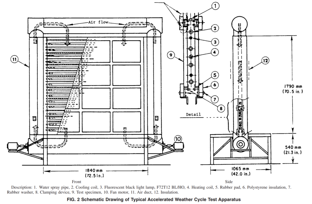
5.2.1 Accelerated Weather Cycle Test Apparatus —The accelerated weather cycle test apparatus shall be essentially that shown in Figs. 1-3 to provide the cycle conditions and time frame indicated in Section 8.
5.2.2 Ultraviolet Light Source:
5.2.2.1 The source shall consist of two fluorescent blacklight lamps, Type F72T12BL/HO5,6 (Note 3), for each test specimen located as shown in Fig. 3.
5.2.2.2 Each lamp must be replaced when its ultraviolet light intensity falls below 10 kW/m2 when measured with a long-wave ultraviolet meter5 in direct contact with the lamp.
NOTE 3—Rated average life at 3 h per start: 12 000 h. Rated average life at 12 h per start: 18 000 h. Useful length: 1625 mm (64 in.). Wattage: 85 W. Relative black light energy output is 190 % that of F40BL lamp.
- Test Specimens
6.1 Each test specimen shall measure 356 +- 6 mm by 508 +- 6 mm (14 +- 1⁄4 in. by 20 +- 1⁄4 in.) and shall be composed of two or three panes of clear, tinted or coated annealed, heat-strengthened, tempered or laminated glass.
6.1.1 The glass and airspace thickness(es) shall be 4 mm (5⁄32 in.) glass and 12 mm (1⁄2 in.) airspace. Alternatively, unit construction can be 5 mm (3⁄16 in.) glass with a 6 mm (1⁄4 in.) airspace.
6.1.2 For triple pane units, 4 mm (5⁄32 in.) glass and 6 mm (1⁄4 in.) airspaces are used.
6.1.3 Triple pane units where the intermediate airspace divider is a plastic film are acceptable.
6.1.4 All of the values in 6.1.1 and 6.1.2 are nominal.
6.1.5 Tolerance of glass thickness shall be in accordance with Specification C 1036.
6.1.6 Airspace tolerance(s) shall be 6 0.8 mm (1⁄32 in.).
6.1.7 Glass or airspace thickness(es), or both, may be increased. This can result in a more rigorous test.
6.2 Each specimen shall be permanently and legibly marked with the designation of the manufacturer and the date of fabrication (month and year).
6.3 At least ten specimens of identical component materials and construction shall be submitted.
6.4 During all stages of exposure and storage, the units shall be stated in a vertical position with equal support to all panes and no compression loading.
6.5 Selection of units for testing shall be made at random except for units damaged in transit. Damaged units shall not be tested.
- Preparation of Test Specimen
7.1 Uncleanable stain or scum may remain on the exterior glass surface of the specimen after the accelerated weathering test. Measures should be taken to have a clear view of the interior glass surface for detection of frost. For example, place a mask of plastic tape 50 by 50 mm (2 by 2 in.) or larger, on the central region of both exterior glass surfaces. Remove the mask for frost point measurement.
7.2 The sealed insulating glass units shall be sealed a minimum of 4 weeks to allow for stabilization before the high humidity exposure in accordance with 8.1 begins. The manufacturer has the option to waive this requirement.
- Procedure
8.1 High Humidity Test:
8.1.1 Expose six specimens in the high-humidity test chamber at 60 +- 3°C (140 +- 5°F) and 95 +- 5 % relative humidity.
Arrange the specimens so that each specimen has at least 6-mm (1⁄4-in.) clearance all around the four sides. Protect the high humidity chamber from overheating with a protective device.
8.1.1.1 Equip the high humidity chamber with a continuous temperature recording device placed in an area that gives the average temperature in the chamber.
8.1.2 When the specified time period has been attained, remove the test specimens and determine the frost point in accordance with Test Method E 546. Observe for chemical dew point.
8.2 Accelerated Weather Cycle Test:
8.2.1 Place the test specimens that were tested in accordance with 8.1 in the accelerated weather cycle test apparatus. Mount the specimens so that one exterior surface of the specimen is exposed to weathering cycles and the other to room temperature (Note 4). Install all specimens as shown in Fig. 2, taking care that no stress is induced in the test specimens by the method of fastening. The test specimens shall be oriented in the accelerated weather cycle exposure with the number one surface facing the weather changes as it does in normal field exposure. Ensure that the bearing edge and the weathering or exposed side remain the same throughout all testing.
NOTE 4—A temperature in the range from 15 to 30°C (60 to 85°F).
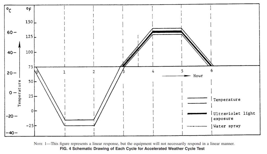
8.2.2 Cycling—Each cycle shall be 6 h6 5 min and composed of the following test condition (see Fig. 4):
8.2.2.1 During the first 1 h +- 5 min, decrease the temperature from room temperature to − 30 +- 3°C (−20 +- 5°F).
8.2.2.2 Maintain temperature at − 30+- 3°C (−20 +- 5°F) for 1 h +- 5 min.
8.2.2.3 Turn on heat and allow temperature to rise from − 30+- 3°C (−20 +- 5°F) to room temperature over a period of 1 h +- 5 min.
8.2.2.4 Over a time period of 1 h 6 5 min, start water spray and ultraviolet lamps and control the temperature rise from room temperature to 57 +- 3°C (135 +- 5°F). Turn off water spray after 30 min to allow temperature to continue to rise to 57 +- 3°C.
8.2.2.5 Maintain temperature at 57 +- 3°C (135+- 5°F) and continue ultraviolet exposure for a period of 1 h +- 5 min. Humidity remains very high during this hour; consequently, additional water spray is not necessary.
8.2.2.6 Over a period of 1 h +- 5 min, decrease temperature from 57 +- 3°C (135 +- 5°F) to room temperature, and continue ultraviolet exposure. At the end of this period, turn off ultraviolet exposure.
8.2.2.7 Protect the accelerated weathering chamber from overheating and from overcooling with protective devices.
8.2.2.8 Equip the accelerated weather cycle chamber with a continuous temperature recording device placed in an area that gives the average temperature inside the chamber.
8.2.3 When the number of cycles prescribed8 has been attained, remove the specimens and determine the frost point in accordance with Test Method E 546.
Accelerated Weathering Test Stand
- Control using computer
- Widows based software
- Reporting in MS WORD including sample general data and graphs
- PLC based
- Capable of maintaining 60 +- 3°C (140 +- 5°F) and 95 +- 5 % relative humidity
- Cyclic control cam be defined in software
- Ultraviolet light source
- Sample dimensions 356*508mm
- Samples installation will be as ASTM E773
- Graphing and saving all data during the test


