4 Principle
The test consists in measuring the force required to tear a specified test piece, in continuation of the cut
or nick already produced in the test piece or, in the case of method B, procedure (a), completely across
the width of the test piece.
The tearing force is applied by means of a tensile testing machine, operated without interruption at
a constant rate of traverse until the test piece breaks. Dependent upon the method employed, the
maximum or median force achieved is used to calculate the tear strength.
No correlation between data obtained by the alternative test pieces is implied.
5 Apparatus
5.1 Dies
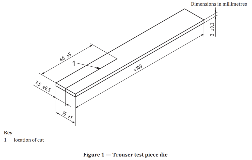
5.1.1 The die used for cutting trouser test pieces shall have the dimensions shown in Figure 1.
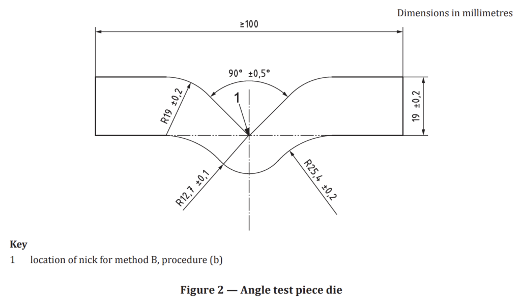
5.1.2 The die used for cutting angle test pieces shall have the dimensions shown in Figure 2.
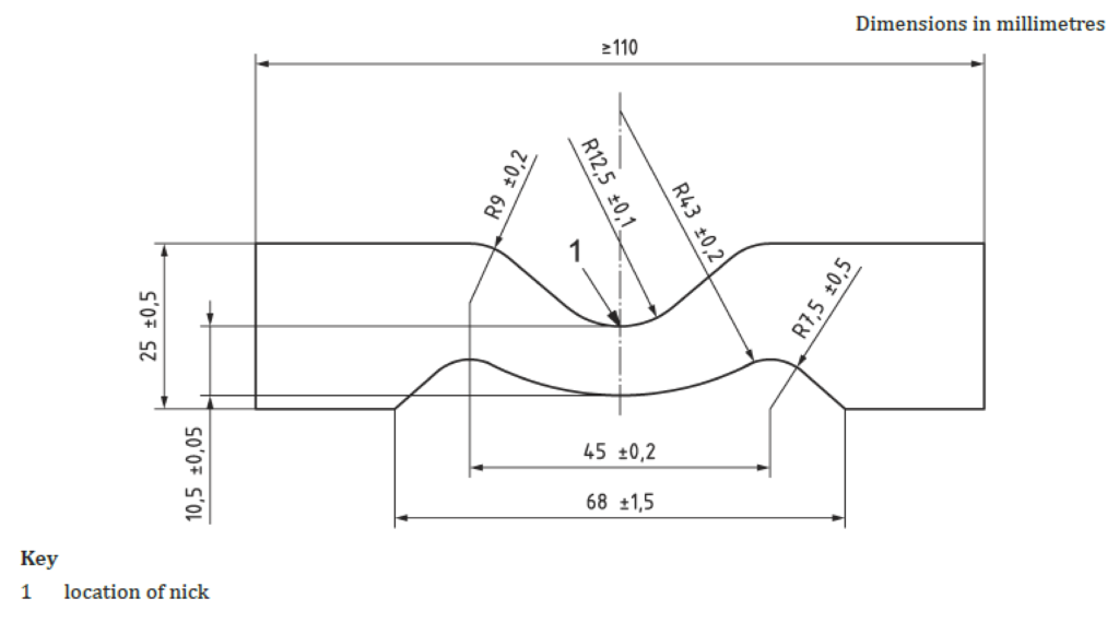
5.1.3 The die used for cutting crescent test pieces shall have the dimensions shown in Figure 3.
5.1.4 The cutting edges of the dies shall be kept sharp and free from ragged edges. Care shall be taken
that the cutting edges are perpendicular to the other surfaces of the die and have a minimum of concavity.
5.2 Nick cutter
A sharp razor blade or a sharp knife free from ragged edges shall be used for producing a cut or a nick
in the test piece.
The apparatus for introducing the nick required for the nicked angle or crescent test piece shall be as follows.
Means shall be provided for clamping the test piece firmly, especially in the region where the nick is to be introduced. The cutting tool, consisting of a razor blade or similar blade, shall be clamped in a
plane perpendicular to the major axis of the test piece, and positioned so as to introduce the nick in the
appropriate place. The blade clamping device shall permit no lateral movement and shall be fitted in
guides to enable the blade to be moved across the test piece with its edge remaining perpendicular to
the plane of the test piece. Alternatively, the blade shall be fixed and the test piece arranged to move in an analogous manner. Means shall be provided for fine adjustment of the depth of the nick. The adjustment of the position of the blade holder or clamped test piece shall be determined for each blade by cutting one or two preliminary nicks and measuring these with the aid of a microscope. The blade shall be wetted with water or soap solution prior to nicking.
NOTE A suitable apparatus for nicking tear test pieces has been described in detail in the literature.[6]To check that the depth of the nick is within the specified limits (see 7.4), any suitable means may be
used, e.g. an optical projection apparatus. A convenient arrangement is a microscope giving at least 10×
magnification fitted with a travelling stage suitably illuminated. The eyepiece is fitted with a graticule
or crosswire by which to record the travel of the stage and test piece through a distance equal to the depth of the nick. The travel of the stage is calibrated with a stage micrometer.
Alternatively, a travelling microscope may be used.
The apparatus shall have an accuracy of measurement of 0,05 mm.
5.3 Testing machine
The machine shall conform to the requirements of ISO 5893, to an accuracy corresponding to class 1. It shall be capable of registering the applied forces within 1 % during the test while maintaining the specified constant rate of separation of the jaws of 100 mm/min ± 10 mm/min for the trouser test piece and 500 mm/min ± 50 mm/min for the angle and crescent test pieces. A low-inertia machine having autographic force-recording facilities is essential when using the trouser test piece.
5.4 Grips
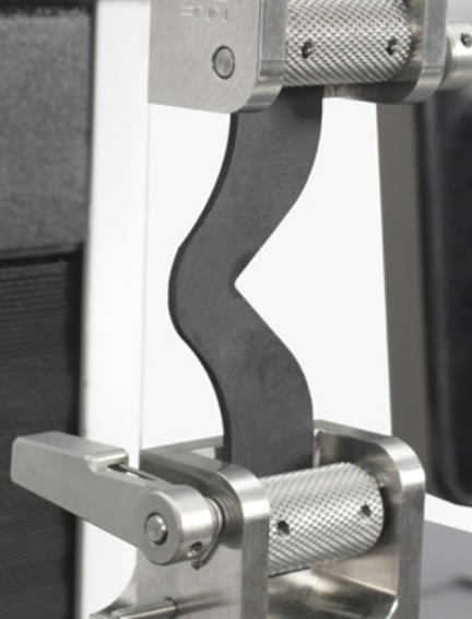
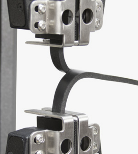
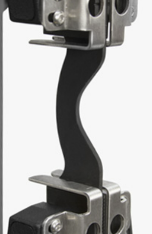
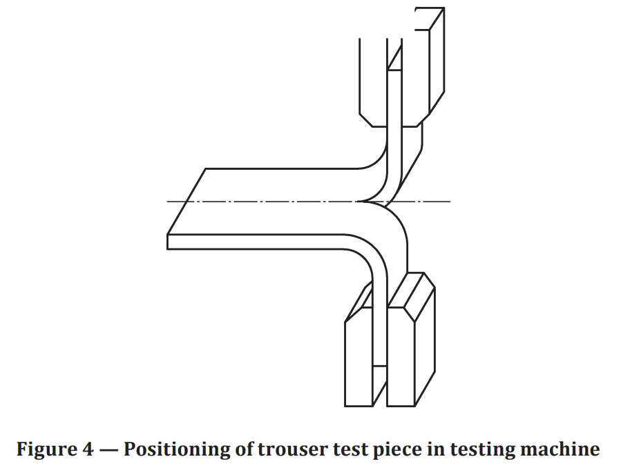
The machine shall be provided with a type of grip which tightens automatically as the tension increases and exerts a uniform pressure across the widened end of the test piece. Each grip shall incorporate a means for positioning so that the test pieces are inserted symmetrically and in axial alignment with the direction of the pull. The depth of insertion shall be such that the test piece is adequately gripped, within the parallel-sides portion, when testing angle and crescent test pieces. Trouser test pieces shall be inserted in the grips in accordance with Figure 4.
7 Test piece
7.1 Test pieces shall be cut from rubber sheet of uniform thickness. Preferably, the sheet shall have a
thickness of 2,0 mm ± 0,2 mm; however, it is recognized that, when sheets are prepared from finished
products, this thickness cannot always be achieved.
Sheets may be moulded or prepared from products by cutting or buffing.
The requirements of ISO 23529 shall apply to the time interval between forming or preparation of the sheet and cutting of test pieces. During this interval, the sheets shall be protected from light as completely as possible.
7.2 The sheets shall be conditioned at standard laboratory temperature (see ISO 23529) for at least 3 h
before test pieces are cut from them.
Each test piece shall be cut from the sheet by punching with a die, shaped as shown in Figure 1, Figure 2
or Figure 3, using a single stroke of the press. The rubber shall be wetted with water or soap solution
and shall be supported on a sheet of slightly yielding material (e.g. leather, rubber belting or cardboard)
on a flat rigid surface.
7.3 Each test piece shall, if possible, be taken in such a way that the tear strength can be determined in
two directions which are at an angle of 90° to one another. The directions in which the test piece is taken
shall be indicated so that the effect of anisotropy can be assessed.
The direction of tear propagation is parallel to the length of the trouser test piece and perpendicular to
the length of the angle and crescent test pieces.
7.4 Test pieces shall be cut or nicked to a depth as given in this subclause by the apparatus specified in 5.2.
Method A (trouser test piece) — Cut of depth 40 mm ± 5 mm made at the centre of the width of the test
piece (see Figure 1). It is important that the last 1 mm (approximately) of the cut is made with a razor
blade or a sharp knife.
Method B, procedure (b) (angle test piece) — Nick of depth 1,0 mm ± 0,2 mm at the apex of the internal
angle of the test piece (see Figure 2).
Method C (crescent test piece) — Nick of depth 1,0 mm ± 0,2 mm at the centre of the concave inner edge of the test piece (see Figure 3).
Test pieces shall be nicked or cut, measured and then tested, preferably immediately, but if not tested
immediately they shall be kept at chosen standard laboratory temperature until tested. The period
between nicking or cutting of the test piece and testing shall not exceed 24 h. The cut or nick shall be
made after any ageing treatment has been carried out.
10 Procedure
Measure the thickness of the test piece in the region in which tearing is expected to occur and in
accordance with ISO 23529. No measurement on any one test piece shall deviate by more than 2 % from
the median value of the thickness of that test piece. If groups of test pieces are being compared, the
median thickness of each group shall be within 7,5 % of the grand median thickness of all the groups.
After conditioning as described in Clause 9, immediately mount the test piece in the testing machine (5.3)
as described in 5.4. Extend the test piece at a rate of separation of the grips of 500 mm/min ± 50 mm/min
for angle and crescent type test pieces and 100 mm/min ± 10 mm/min for trouser test pieces until the
test piece breaks. Record the maximum force for crescent and angle test pieces. When using trouser test
pieces, make an autographic recording of the force throughout the tearing process.
11 Expression of results
The tear strength Ts, expressed in kilonewtons per metre of thickness, is given in Formula (1):

where
F is the maximum force, in newtons, when using method B or C, and the median force, in newtons,
calculated in accordance with ISO 6133, when using method A;
d is the median thickness, in millimetres, of the test piece.
Determine the median and the range of the values for each direction of testing.
Express the results to the nearest kilonewton per metre.