

Unpacking
The machine will go to the customer with the main machine, anvils, and pendulums as per order. Power cable is also in the pack. Place the machine on very robust table.
Power
The main power for this model is less than 500W in a single phase. The power cable will come to you that is 16A capacity and you need to use a proper safety fuse between the main power and the machine.
You can order the machine with your specific type of connectors. Unless it will come with a double-pin socket excluding the earthing connection (The earth connection will be connected to the machine’s body separately).
How to operate
Put the proper anvils and pendulum as needed. You need to select proper energy and angle of release of the pendulum on the touch display. Then measure the friction loss of the attached pendulum.
Next step , just attach the sample to the sample holder and be ready for testing.
How to calibrate for proper pendulum
go to the calibration screen. release the pendulum to be in a vertical position. The vertical position is where the impact point of the hammer touches the face of the sample with no force. Then click “Zero”. Then enter the release angle value of the machine on the “release angle”. bring the pendulum to the starting position and then click “Cal”. Now the angle of the pendulum is just calibrated. Also, you need to enter the “Mounted weight(jouls)”. On the pendulum, there is a marking showing the impact energy of the hammer.

Calculation of friction loss
Go to the friction loss measurement page.

Bring the pendulum to the starting position without a sample piece and then release the pendulum. Afterward, click on the “F.L” key on the screen. Then the friction loss will be saved.
Sample parameters

Select the type of sample piece and enter the parameters of the sample piece on this page.
Test Start
After calibration, measurement of friction loss and putting sample piece on the holder now you are ready to start the test. Go to the test start page.
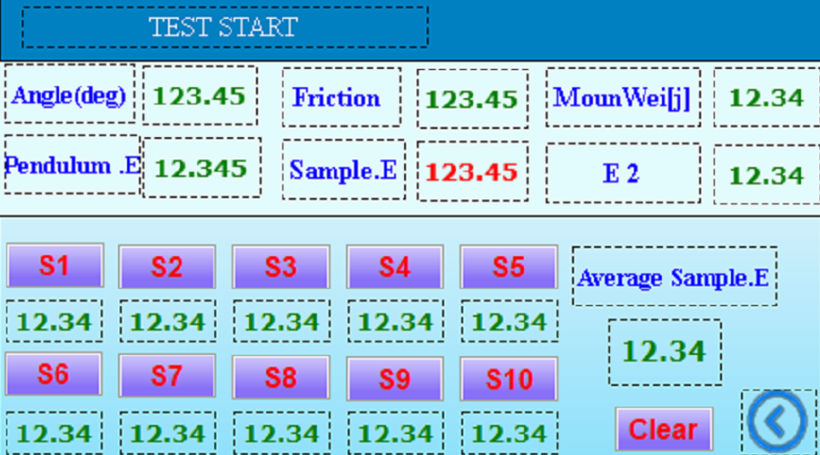
First, click on “Clear” to clear the last results that being saved.
Bring the pendulum to the starting position and release the pendulum. The machine will measure the impact energy automatically and show it on the “Sample E”. Any time you test a sample piece after the test is finished click on “S1” to “S10” to save the energy value on the proper location relating to the sample number. After each test, you will also have “Average Sample E” on the screen.
Saving the results
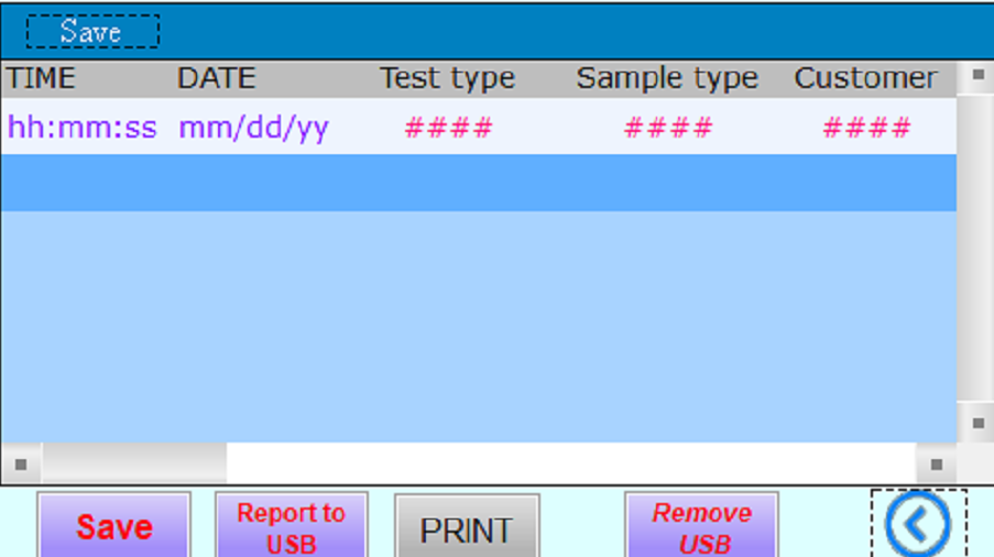
On this screen, you can save the results in the internal memory and also print the last result. Anytime you click on “Save” machine will add a row to the internal memory data including all sample data and test results. If you put a USB flash disk on the USB data out of the machine and click on “REPORT to USB” you will have internal memory data on the flash disk as MS EXCEL sheet.
IZOD Test Procedure as per ISO 180
5 Apparatus
5.1 Test machine
5.1.1 The principles, characteristics and verification of suitable test machines are detailed in ISO 13802.
6 Test specimens
6.1 Preparation
6.1.1 Moulding and extrusion compounds
Specimens shall be prepared in accordance with the relevant material specification. When none exists, and unless otherwise specified, specimens shall be either directly compression moulded or injection moulded from the material in accordance with ISO 293, ISO 294-1, ISO 295 or ISO 10724-1 as appropriate, or machined in accordance with ISO 2818 from sheet that has been compression or injection moulded from the compound. Specimens may also be cut from multipurpose test specimens complying with ISO 3167, type A.

6.1.2 Sheets
Specimens shall be machined from sheets in accordance with ISO 2818. Whenever possible, specimens with notch A shall be used. The machined surface of unnotched specimens shall not be tested under tension.
6.1.3 Long-fibre-reinforced materials
A panel shall be prepared in accordance with ISO 1268 or another specified or agreed upon preparation procedure. Specimens shall be machined in accordance with ISO 2818.
6.1.4 Checking
The specimens shall be free of twist and shall have mutually perpendicular parallel surfaces. The surfaces and edges shall be free from scratches, pits, sink marks and flash.
The specimens shall be checked for conformity with these requirement by visual observation against straightedges, squares and flat plates, and by measuring with micrometer callipers.
Specimens showing measurable or observable departure from one or more of these requirements shall be rejected or machined to proper size and shape before testing.
6.1.5 Notching
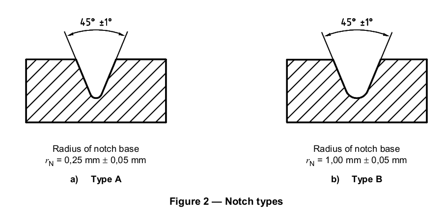
6.1.5.1 Machined notches shall be prepared in accordance with ISO 2818. The profile of the cutting tooth shall be such as to produce in the specimen a notch of the contour and depth shown in Figure 2, at right angles to its principal axes. The notch profile shall be checked at regular intervals.
6.1.5.2 Specimens with moulded-in notches may be used if specified for the material being tested. Specimens with moulded-in notches do not give results comparable to those obtained from specimens with machined notches. The notch profile shall be checked at regular intervals.
6.3 Shape and dimensions
6.3.1 General
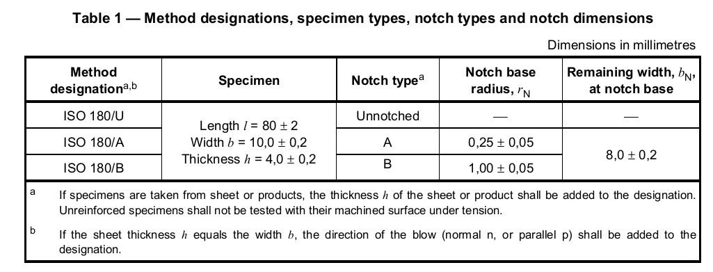
For the dimensions of the test specimen, see Table 1.
Where necessary with certain types of apparatus, the length may be shortened symmetrically to 63,5 mm.
The longitudinal direction of the notch is always parallel to the thickness h.
6.3.2 Moulding and extrusion compounds
Test specimens with one of two different types of notch shall be used as specified in Table 1 and shown in Figure 2. The notch shall be located at the centre of the specimen.
The preferred type of notch is type A. If information on the notch sensitivity of the material is desired, specimens with notch types A and B shall be tested.
6.3.3 Sheet materials, including long-fibre-reinforced materials
The recommended thickness h is 4 mm. If the specimen is cut from a sheet or a piece taken from a structure, the thickness of the specimen, up to 10,2 mm, shall be the same as the thickness of the sheet or the structure.
Specimens taken from pieces thicker than 10,2 mm shall be machined to 10 mm ± 0,2 mm from one surface, providing that the sheet is homogeneous in its thickness and contains only one type of reinforcement uniformly distributed. If unnotched specimens are tested, the original surface shall be tested under tension, in order to avoid surface effects.
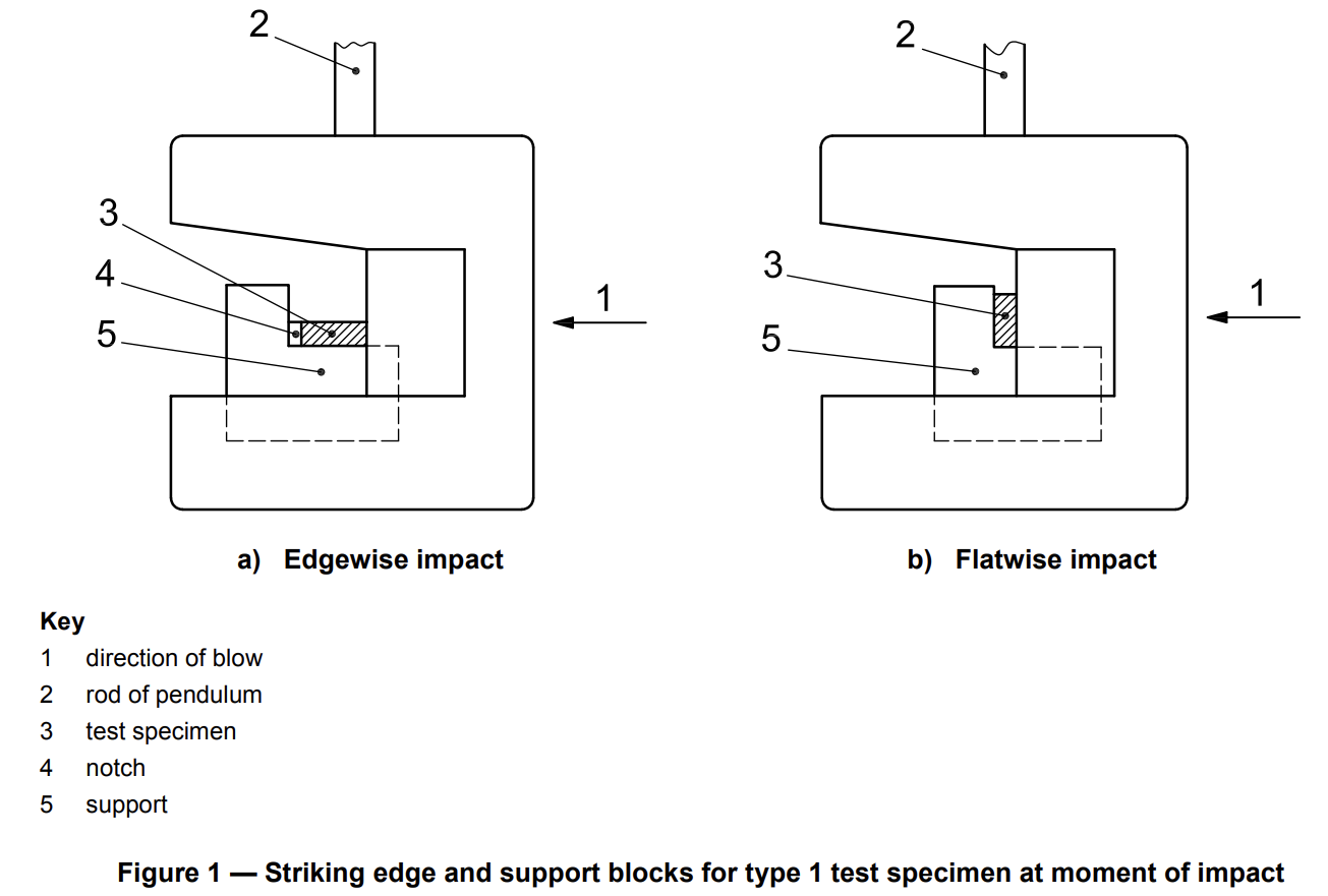
Specimens shall be tested edgewise parallel, with the exception of specimens with h = b =10mm which can be tested parallel or normal to the laminate plane (see Figure 1).
6.4 Number of test specimens
6.4.1 Unless otherwise specified in the standard for the material being tested, a set consisting of 10 specimens shall be tested. When the coefficient of variation (see ISO 2602) has a value of less than 5 %, a minimum number of five test specimens is sufficient.
6.4.2 If laminates are tested in the normal and parallel directions, 10 specimens shall be used for each direction.
6.5 Conditioning
Unless otherwise specified in the standard for the material under test, the specimens shall be conditioned for at least 16 h at 23 °C and 50 % relative humidity in accordance with ISO 291, unless other conditions are agreed upon by the interested parties. In the case of notched specimens, the conditioning time is after notching.
7 Procedure
7.1 Conduct the test in the same atmosphere as that used for conditioning, unless otherwise agreed upon by the interested parties, e.g. for testing at high or low temperatures.
7.2 Measure the thickness h and width b of each test specimen, in the centre, to the nearest 0,02 mm. In the case of notched specimens, carefully measure the remaining width bNto the nearest 0,02 mm.
In the case of injection-moulded specimens, it is not necessary to measure the dimensions of each specimen. It is sufficient to measure one specimen from a set to make sure that the dimensions correspond to those in Table 1. With multiple-cavity moulds, ensure that the dimensions of the specimens are the same for each cavity.
7.3 Check that the impact machine is able to perform the test with the specified velocity of impact and that it is in the correct range of absorbed energy W which shall be between 10 % and 80 % of the available energy at impact, E. If more than one of the pendulums conform to these requirements, the pendulum having the highest energy shall be used.
7.4 Determine the frictional losses and correct the absorbed energy in accordance with ISO 13802.
7.5 Lift the pendulum to the prescribed height and support it. Place the specimen in the vice and clamp it as shown in Figure 1, in accordance with 5.1.2. When determining the notched Izod impact strength, the notch shall be positioned on the side that is to be struck by the striking edge of the pendulum.
7.6 Release the pendulum. Record the impact energy absorbed by the specimen and apply any necessary corrections for frictional losses, etc. (see 7.4).
7.7Four types of break designated by the following code-letters may occur:
C complete break: a break in which the specimen separates into two or more pieces
H hinge break: an incomplete break such that both parts of the specimen are held together only by a thin peripheral layer in the form of a hinge having low residual stiffness
P partial break: an incomplete break that does not meet the definition for hinge break
N non-break: there is no break, and the specimen is only bent and pushed through the support blocks, possibly combined with stress whitening
8 Calculation and expression of results
8.1 Unnotched specimens
Calculate the Izod impact strength of unnotched specimens, aiU, expressed in kilojoules per square metre, using the following equation:

Ec is the corrected energy, in joules, absorbed by breaking the test specimen;
h is the thickness, in millimetres, of the test specimen;
b is the width, in millimetres, of the test specimen.
8.2 Notched specimens
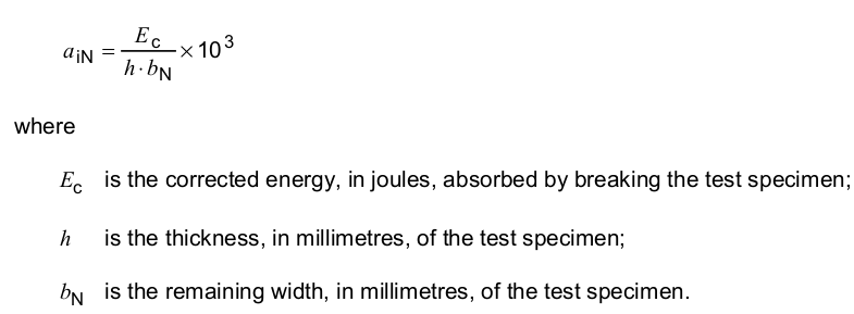
Calculate the Izod impact strength of notched specimens, aiN, expressed in kilojoules per square metre, with notches A or B, using the following equation:
ISO 179 Plastics — Determination of Charpy Impact Properties / Brief Test Method and Required Equipment
5 Apparatus
5.1 Test machine
The principles, characteristics and verification of suitable test machines are detailed in ISO 13802. ISO 13802 describes partial verification and full verification. In the case of full verification, some items are difficult to verify when the apparatus is assembled. Such verifications are assumed to be incumbent on the manufacturer.
5.2 Micrometers and gauges
Micrometers and gauges capable of measuring the essential dimensions of test specimens to an accuracy of 0,02 mm are required. For measuring the dimension bN of notched specimens, the micrometer shall have a spindle with a measuring tip having a suitable profile to fit the shape of the notch.
6 Test specimens
6.1 Preparation
6.1.1 Moulding and extrusion compounds
Specimens shall be prepared in accordance with the relevant material specification. The specimens shall be either directly compression moulded in accordance with ISO 293 or ISO 295 or injection moulded from the material in accordance with ISO 294-1, ISO 294-3 or ISO 10724-1, as appropriate, or machined in accordance with ISO 2818 from sheet that has been compression or injection moulded from the compound. Type 1 specimens may be cut from multipurpose test specimens complying with ISO 3167, type A.
6.1.2 Sheets
Specimens shall be machined from sheets in accordance with ISO 2818.
6.1.3 Long-fibre-reinforced materials A panel shall be prepared in accordance with ISO 1268-11 or another specified or agreed upon preparation procedure. Specimens shall be machined in accordance with ISO 2818.


6.1.4 Checking
The specimens shall be free of twist and shall have mutually perpendicular parallel surfaces. The surfaces
and edges shall be free from scratches, pits, sink marks and flash.
The specimens shall be checked for conformity with these requirements by visual observation against
straightedges, set squares and flat plates, and by measuring with micrometer callipers. Specimens showing measurable or observable departure from one or more of these requirements shall be rejected or machined to proper size and shape before testing.
6.1.5 Notching
6.1.5.1 Machined notches shall be prepared in accordance with ISO 2818. The profile of the cutting tooth
shall be such as to produce in the specimen a notch of the contour and depth shown in Figure 5, at right
angles to its principal axes (see Note).
NOTE The radius of the notch tip can be measured by the method given in Annex C. 6.1.5.2 Specimens with moulded-in notches may be used if specified for the material being tested (see Note).
NOTE Specimens with moulded-in notches do not give results comparable to those obtained from specimens with machined notches.

6.3 Shape and dimensions
6.3.1 Materials not exhibiting interlaminar shear fracture
6.3.1.1 Moulding and extrusion compounds
6.3.1.1.1 Type 1 test specimens, unnotched or with one of three different types of notch, shall be used as
specified in Tables 1 and 2 and shown in Figures 2 and 5. The notch shall be located at the centre of the
specimen. Type 1 specimens (see Table 1) may be taken from the central part of the type A multipurpose test specimen specified in ISO 3167.

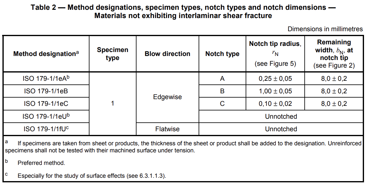
6.3.1.1.2 The preferred type of notch is type A (see Table 2 and Figure 5). For most materials, unnotched
specimens or specimens with a single type A notch tested by edgewise impact (see 3.3) are suitable. If
specimens with a type A notch do not break during the test, specimens with a type C notch shall be used. If information on the notch sensitivity of the material is desired, specimens with notch types A, B and C shall be tested.
6.3.1.1.3 Unnotched or double-notched specimens tested by flatwise impact (see 3.4) can be used to study surface effects (see 1.3 and Annex A).
Summary of Equipment Needed to Do the Test
- Pendulum Impact Tester
- Manual Injection Molding Machine
- Notch Milling Machine
- Deep Freezer
- Hot Press (Manual or Hydraulic)