
4 Apparatus
4.1 Compression tester, motor-driven, platen-type, capable of applying load through uniform movement of one or both platens at a relative speed of 10 mm/min ± 3 mm/min.
NOTE 1 The comparison between results obtained from apparatus operated at other speeds (for example 12,5 mm/min ± 2,5 mm/min) and results obtained at 10 mm/min ± 3 mm/min is not recommended.
NOTE 2 For certain packagings, such as metal drums or wooden crates, lower speeds may be required to prevent load peaks in excess of the predetermined value.
4.1.1 Platens
Each platen shall be -flat;
a) with a tolerance of 1 part in 1 000 for surface areas < 1 m²; b) for surface areas > 1 m², such that when placed horizontally the difference in height between the lowest and highest points of the platen does not exceed 1 mm; dimensioned so as to extend over the whole area of that side of the test package or interposed devices with which it is in contact;
-rigid, so as not to deform by more than 1 mm at any point when the tester applies a load of 75% of its maximum rating, either to a centrally placed 100 mm × 100 mm × 100 mm block having sufficient strength to accept the load without failure, or to four similar blocks placed at the four corners, in the case of swivel-mounted platens.
One platen shall remain horizontal, within a tolerance of two parts per 1000, at all times during the test. The other platen shall be either rigidly mounted so as to remain horizontal within two parts per 1000 at all times during the test, or be held by a universal joint at its centre and so be free to tilt in any direction.
The working surfaces of the platens may be locally recessed for fixing bolts etc.
4.1.2 Means of applying a predetermined load for a predetermined time, with a fluctuation not exceeding ± 4% of the predetermined load and with no more relative movement of the platens than is necessary to maintain this load during any vertical displacement of the upper platen.
4.2 Recording device or other means of indicating applied load and platen displacement, with a percentage of error not exceeding 2% of the load and an accuracy for recording platen displacement of± 1 mm.
4.3 Means of measuring package dimensions with an accuracy of ± 1 mm.
7 Procedure
Wherever possible the test shall be carried out in the same atmospheric conditions as used for conditioning, where this is critical to the materials or application of the package. In other circumstances, the test shall be carried out in atmospheric conditions which are as near as practicable to those used for conditioning. When possible, carry out the test on five replicate packages.
7.1 Compression test
7.1.1 Weigh the package and its contents separately, fill the package and measure the external dimensions of the filled package.
7.1.2 Place the test package centrally on the lower platen of the test machine (4.1), in the predetermined attitude.
When the compression load is not to be applied over the whole surface of the package which is being tested, appropriate devices should be suitably interposed between the package and platen of the compression tester in order to simulate the conditions met in distribution systems when applying these compression loads.
7.1.3 Apply the load by relative movement of the platens at the appropriate speed, in such a way that peaks in excess of the predetermined load do not occur, until the predetermined value is reached or until collapse occurs, whichever is first. If collapse occurs first, record the value of the load reached.
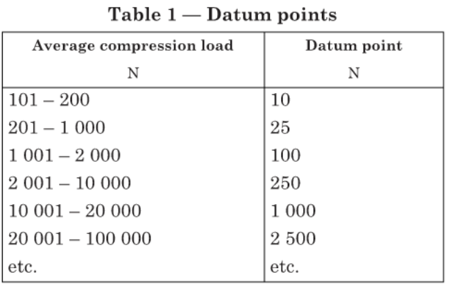
In measuring deformation, the initial reading (the datum point), unless otherwise specified, shall be taken at an initial load which is a function of the expected average compression load according to Table 1.
7.1.4 If required, maintain the predetermined load for a predetermined time or until collapse occurs, whichever is first. If collapse occurs first, record the value of the time elapsed.
7.1.5 Remove the load by movement of the platens, examine the package and, if collapse has occurred, measure its dimensions and examine the contents for damage.
7.1.6 Where it is desired to measure the ability of a complete, filled transport package to resist external compressive loads applied to opposite edges or corners of the package, follow the procedure in 7.1.1 to 7.1.5, using a tester in which the platens are not free to tilt.
7.2 Stacking test
NOTE 3 A stacking test on a complete, filled transport package, using one of three methods of applying a static load, is given in ISO 2234.
7.2.1 Proceed as in 7.1.1 to 7.1.3 and maintain the predetermined load for a predetermined time or until collapse occurs, whichever is first. If collapse occurs first, record the value of the time elapsed.
NOTE 4 Where it is desired to measure the ability of a complete, filled transport package to resist external compressive loads applied during stacking, a tester with one fixed platen is preferred.
7.2.2 Remove the load by movement of the platens, examine the package and, if collapse has occurred, measure its dimensions and examine the contents for damage.
NOTE 5 At any time during the test it may be necessary to measure dimensions (see Annex A).
NOTE 6 Appropriate profiles representative of particular loading conditions may be inserted between platens and package as required.