5 Test methods
5.1 General
5.1.1 Test conditions
Any suitable test system can be used that enables the required accuracy (determined by calibration) and precision (determined by Gauge R&R) to be obtained. The repeatability and reproducibility (Gauge R&R) of the test apparatus shall not exceed 20 % of the allowed tolerance range for any given measurement. For destructive test measurements, the Gauge R&R shall not exceed 30 % of the allowed tolerance range. At a minimum, the Gauge R&R should cover ±2 standard deviations (thereby covering approximately 95 % of the variation).
EXAMPLE A measurement system with a measurement specification limit of ±0,01 ml (range of 0,02 ml) comes out of the Gauge R&R with a Gauge R&R/tol. range ratio of 20 %, which means that the Gauge R&R (four standard uncertainties) equals 0,02 ml/5 = 0,004 ml. The uncertainty of the measurement is ±2 standard deviations (see ISO/IEC Guide 98-3), which equals 0,002ml.
NOTE Some of the requirements in this part of ISO 11608 only have one-sided limits, in which case the Gauge R&R should only be used to find the R&R standard deviation. The measurement uncertainties are calculated as 2 × R&R standard deviations.
The manufacturer shall define and describe the tests that are required to demonstrate the functionality of any and all automated functions for the system.
This shall be confirmed after pre-conditioning (to be determined during testing in accordance either with ISO 11608-1 or procedures to be specified in this part of ISO 11608).
Unless otherwise specified, all tests and test evaluations shall be performed at standard atmosphere conditions (as defined in ISO 11608-1). Consideration shall be given to the sequential operation of a NIS-AUTO when testing. Where the design of a NIS-AUTO allows operations to be performed in a sequence other than that specified, the manufacturer shall document how the risks of out-of-sequence operation have been addressed
5.1.2 Drug product preparation (e.g. reconstitution)
The manufacturer shall confirm that the drug product prepared automatically within the NIS-AUTO, when used according to the instructions for use, meets the drug product specification. Confirmation will normally be achieved by at least visual means, according to the drug product specification.
5.1.3 Needle preparation
Automated needle preparation shall be performed according to the instructions for use. Following this, the needle tip shall be inspected, using optical magnification where appropriate to confirm that there is no obvious damage to the needle tip. The NIS-AUTO shall perform all subsequent functions within the specified parameters.
5.1.4 Air removal and/or priming
Automated air removal and/or priming shall be performed in accordance with the instructions for use. Following this, the NIS-AUTO shall still be able to deliver the specified volume of drug product specified in the requirements in accordance with ISO 11608-1.
5.1.5 Automatic dose setting and memory
Where the dose delivered is variable and may be set automatically, the values of Vmin, Vmid and Vmax used in dose accuracy assessment shall be appropriate to the range that may be set automatically.
Where the NIS-AUTO is intended to display the previously set dose, the dose displayed shall be verified as that previously set and confirmed through a subsequent dose accuracy measurement.
5.1.6 Actuation
Each of the manual steps leading to an automated injector sequence shall be undertaken according to the instructions for use and measurements made, where appropriate (for example, torque to rotate a safety lock or force to operate a button). This ensures that the initiation of each step is within the specified limits.
Where the design permits only sequential operation, the steps shall be undertaken in sequence.
Where the design permits non-sequential operation, the steps shall be undertaken in each of the possible sequences. In whichever order the steps are undertaken, the NIS-AUTO shall not start the automated injection until all of the steps are completed.
5.1.7 Needle extension
The axial distance from the patient end of the needle tip to the nearest part of the NIS-AUTO body (defining the point of contact with the patient adjacent to the injection site) shall be measured during normal operation of the NIS-AUTO. Measurement may be by mechanical, optical or other means, but shall not affect the position of the needle tip. The distance measured shall be within the specification for the NIS-AUTO.
5.1.8 Injection
Dose accuracy shall be determined according to the dose accuracy method of ISO 11608-1.
Dose accuracy testing may be modified using the method specified in 5.1.9.1 for NIS-AUTOs that combine automated insertion and/or retraction with the injection.
5.1.9 Needle insertion and needle retraction
5.1.9.1 Dose accuracy
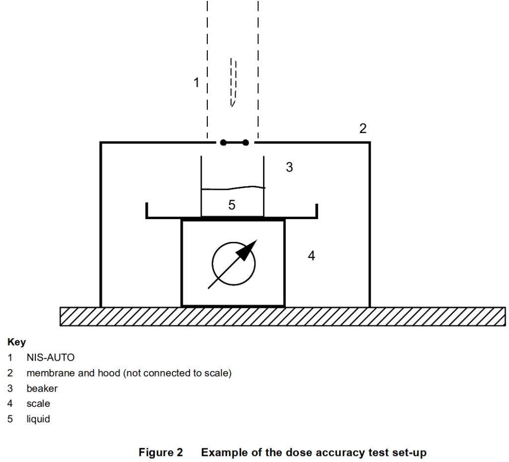
Using the dose accuracy method specified in 5.1.8, a membrane shall be placed over the measurement container flush with the surface around the opening of the NIS-AUTO (shown in Figure 2).
The volume of drug delivered before penetration of the membrane and after extraction from the membrane shall be excluded from the calculation of dose accuracy. The membrane shall not allow any liquid to flow into the measurement container other than that through the needle and shall not adversely affect the needle insertion or retraction.
For uses of the injector whereby the risk assessment determines that the intended injection site starts at a depth greater than skin level, the position of the membrane shall be adjusted accordingly away from the end of the injector.
Other methods are permitted. One alternative might be a two-staged approach: using high-speed photography, confirm that expression of the full dose begins and ends within a pre-specified percentage (based on the intended injection depth) of the needle extension. For example, with a 10 mm needle extension, a 30 % allowance would require that fluid expression begin and end with the needle extended at least 7 mm. Then satisfy standard dose accuracy requirements as given in ISO 11608-1.
5.1.9.2 Retracted position
The NIS-AUTO shall be operated according to the instructions for use. At the end of the retraction function the axial distance from the needle tip to the front-most part of the NIS-AUTO body (defining the point of contact with the patient adjacent to the injection site) shall be measured.
5.1.10 Disabling the NIS-AUTO
The disabled NIS-AUTO shall be subjected to the conditions specified for normal actuation and the actuation force (where appropriate) shall be increased to at least two times the specified maximum for normal actuation. The NIS-AUTO shall not perform any part of its normal actuation.
The NIS-AUTO shall not perform any part of its disabled functionality.
The same NIS-AUTO shall then be subjected to free fall in a non-turbulent way from a height of 1 000 mm onto a 3-mm-thick hard, smooth steel surface backed with wood of minimum thickness of 10 mm, in the following positions:
a) horizontally;
b) vertically on one end;
c) vertically on the opposite end to b).
The NIS-AUTO shall not perform any part of its disabled functionality during any of these falls.
5.1.11 Pre- and post-injection needle hiding and shielding
5.1.11.1 Needle hiding
The test method shall be conducted in such a way that the feature that hides the needle prevents visibility of the needle through the material (e.g. opaque or non-transparent material). The visibility of the needle through the opening for needle travel, before and after injection, is shown in Figure 3.
5.1.11.2 Needle shielding
If the NIS-AUTO includes a lock-out feature, it shall withstand a minimum load as determined from the risk assessment (at least two times its actuation force), which shall be applied to the surface around the opening of the NIS-AUTO using a flat plate. The plate dimensions shall be larger than the NIS-AUTO profile so that the application of the force onto the surface around the opening is entirely within the plate. Under the application of this load, the needle tip shall not touch the flat plate.
5.2 Dose specification requirements
The dose accuracy of the NIS-AUTO shall be determined by the procedures described in ISO 11608-1.


