
6 Performance requirements
6.1 Operating torque
The measured operating torque shall not exceed the values given in Table 7.
The torque required for the preliminary cycle shall not be greater than 1,5 times for valves up to DN 15 and 2,5 times for DN 20 up to DN 100 of the values given in Table 7.
6.2 Stop resistance
The valve shall be tested in accordance with 7.3. There shall be no visual deformation, cracking or failure.
6.3 Leak-tightness
The valve shall be leak-tight.
The valve shall be considered leak-tight if it meets the tests detailed in 7.4.
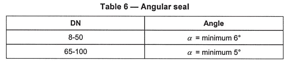
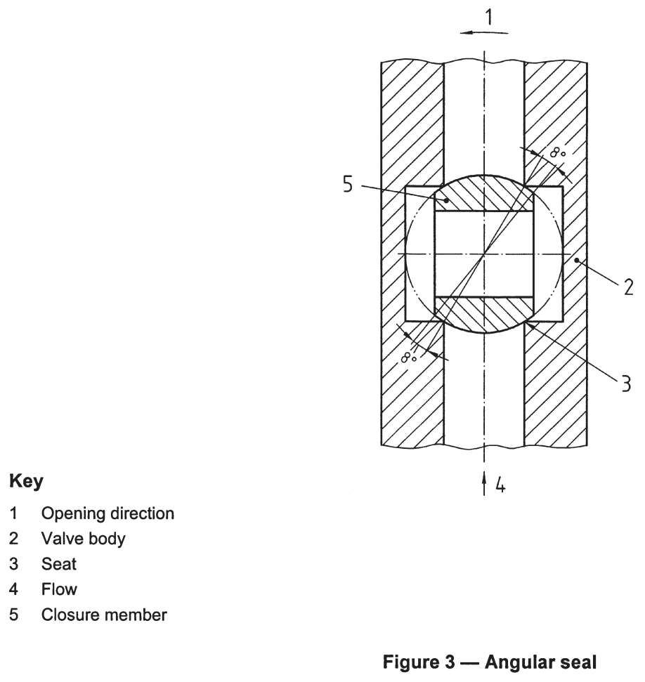
6.4 Angular seal
With the valve in the fully closed position, the angular distance between the port in the closure member and both the inlet port and outlet port in the valve body, shall be at least values according to Table 6 when measured according to 7.7 (see Figure 3).
7 Test methods
The tests described are type tests (laboratory tests) and not quality control tests carried out during manufacture.
Tests 7.1 to 7.6 shall be carried out in the sequence of this standard on the same ball valve.
All tests shall be carried out with cold water of (20 ± 5) °C.
7.1 Operating torque test
Before starting the test, one preliminary cycle shall be carried out. The valve shall then be left for 24 h at ambient temperature.
The operating torque of the valve is measured continuously from the fully open position to the fully closed position and then back to the fully open position while it is subjected to the static PN 10. During the test the speed of the rotation shall be 5 ± 1 cycles per minute.

7.2 Torque and bending test
7.2.1 General
Hold the ball valve in a rigid fixture as shown in Figure 4.
a) All tests shall be carried out with connections to the valves (whatever their end fitting configurations) which are capable of withstanding the required torque values and bending moments (according to Table 8 and Table 9):
b) if the inlet and outlet connection are not on a common axis, the torque tests shall be repeated with the connections reversed;
C) ensure that the bending and torsional moments can be attained vvith an accuracy of 5,0 % of the specified values;
d) if the valve has different inlet and outlet connection, the larger connection shall be used for pipe 1 (see Figure 4 and Figure 5);
e) the pipes for the testing of connections shall conform to ISO 65, medium series, and have a length of 1 m;
f) for valves with end fittings which are especially designed for use only with flexible connections, only tests on torque MT1, and bending moment MF1, are carried out.
7.2.2 Sequence of torsion and bending moment tests for valves
7.2.2.1 Torque
(See Figure 4).
This test is only applicable to ball valves with internal threads on both sides. The torque shall be applied in both directions.
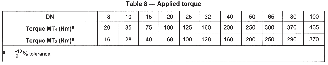
The stress MT1 represents the installation stress.
The stress MT2 represents the stress to which the valve may be submitted during service.
The valve shall be under nominal pressure for these tests.
7.4 Hydraulic tests
7.4.1 Leak-tightness test
7.4.1.1 Principle
This test shall verify the leak-tightness of the ball (internal tightness) and the ball valve assembly (external
tightness) under cold water pressure.
7.4.1.2 Test
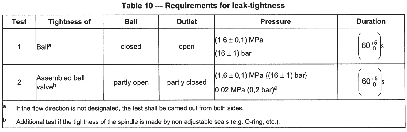
Install the ball valve in a test rig capable of maintaining the static pressures indicated in Table 10.
For test 1, close the ball using a torque which is not greater than the values in Table 7.
Subject the ball valve to the pressures indicated in Table 10 for 60+5 s
7.4.1.3 Requirement
The ball valve shall be leaktight at the pressures indicated in Table 10.
7.4.2 Hydraulic strength
7.4.2.1 Principle
This test shall verify that the ball valve withstands a cold water hydraulic pressure.
7.4.2.2 Test
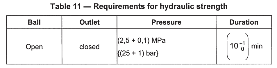
Install the valve in a test rig, capable of maintaining the static pressures indicated in Table 11.
Subject the ball valve, with the ball open and the outlet closed to a pressure of (2,5 ” 0,1) MPa {(25 ” I) bar} for 10+1 min
Leaking at spindle sealing and end connection is allowed.
7.4.2.3 Requirement
The ball valve shall show no permanent deformation, rupture or breakage at the pressure indicated in Table 11.
7.6 Endurance test
7.6.1 Principle
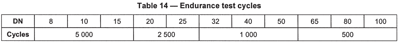
The manual actuator of the valve shall withstand a series of operating cycles as specified in Table 14.
7.6.2 Test installation
An automatic test rig that ensures that the closing torque remains constant and is not effected by the influence of the moment of inertia of the equipment during test.
Equipment related forces that act horizontally or vertically onto the headwork and might result in abnormal wear ought to be eliminated. A frictionless connection to the operating spindle shall be ensured.
7.6.3 Test
7.6.3.1 Conditions
Apply a closing torque according to Table 7. With the ball valve in the closed position adjust the static pressure to between 0,2 MPa and 0,4 MPa (2 bar and 4 bar). With the ball valve in the open position adjust the flow rate to between 0,066 l/s and 0,1 l/s (4 l/min and 6 l/min) by a regulation valve downstream of the valve under test.
7.6.3.2 Procedure
I)Open the valve completely and mount the valve to the test rig;
2)close the valve with a speed of the ball 5 rev./min. and stop the movement without submitting the stops to a torque exceeding the appropriate value given in Table 7;
3) hold the valve 5 s in closed position;
4)open the valve with a speed and torque as given in point 2;
5)hold the valve 5 s in open position;
6) repeat the procedure given in points 1 to 5 for 50 % of the number of cycles given in Table 14;
7)store the valve for one week at ambient temperature in open position;
8) mount the valve in closed position to the test rig and apply water of 65 °C;
9) repeat the procedure given in points 1 to 5 for 50 % of the number of cycles given in Table 14 at a water temperature of 65 °C;
10) store the valve for one week at ambient temperature in closed position;
11) the valve shall comply with 7.6.3.3.
The test is applied to ball valves as delivered.
7.6.3.3 Acceptance criteria
I) If leakage or malfunction occurs test shall be stopped;
2) 1 ‘week after concluding the tests, stored in open position at ambient temperature, the valve shall comply vvith the leak tightness test (7.4.1) and operating torque test (7.1).
7.7 Angular seal
Mount the complete valve on a test rig which is capable of measuring the angle of rotation of the actuator (e.g. a 360° graduated scale and pointer mounted on the handle or control lever).
Connect the inlet of the valve to a compressed air supply of 6 bar pressure through a bubble indicator (or similar flow measuring device). The air flow through the valve is limited to a value between 1 l/h and 5 I/h by means of a flow restrictor connected to the outlet of the valve.
Slowly open the valve until the flow measuring device indicates flow, then slowly close the valve until the flow measuring device indicates no flow. Measure the angle between the closed position and the “no flow” position. The measured values shall be in accordance with 6.4.
For sizes DN 65, 80, 100 the test is carried out at 6 bar pressure with water instead of air.