
8 Test specimens and conditions
8.1 Test specimens
The sample shall include 25 specimens taken at random from a lot of at least 500 emitters/emitting units. A specimen is composed of either one emitter or one non-truncated emitting unit from the emitting pipe. The number of test specimens (emitters/emitting units) required for each test is indicated in Clause 9 for the relevant tests. For emitting pipes, ensure that the test specimen is not taken from adjacent sections of the pipe and does not contain either the first or last emitting unit of the lot. For multiple outlet emitters, the sample shall include at least 10 emitters or 25 outlets.
8.2 Order of tests
The tests shall be conducted in the order given in Clause 9. All tests, beginning with that of 9.2, shall be
conducted on specimens tested according to 9.1.
8.3 Test conditions
Unless otherwise specified, carry out all tests at ambient air temperature and at a water temperature of
23 °C ± 3 °C. Ensure that the water used is clear water filtered through a filter with nominal aperture of 75 µm to 100 µm, or as recommended by the manufacturer, with a total load of contaminants not exceeding 25 mg/l.
8.4 Accuracy of measuring devices
The water pressure shall be measured with measuring devices capable of measuring with an error not
exceeding 1 % of the actual values.
During the test, the pressure shall not vary by more than 2 %.
The flow rate shall be measured with measuring devices capable of measuring with an error not exceeding ± 0,5 % of the nominal flow rate.
9 Test methods and requirements
9.1 Uniformity of flow rate
9.1.1 General
This test applies to regulated and unregulated emitters/emitting pipes. The test sample shall include 25
emitters/emitting units in accordance with the requirement in 8.1. When multiple emitters are tested, each outlet shall be considered as a single emitter.
9.1.2 Unregulated emitters/emitting pipes
Measure the flow rates of the emitters/emitting units when the water pressure at the inlets of the
emitters/emitting units equals the nominal test pressure. Record separately the measured flow rate of each emitter/emitting unit.
Calculate the coefficient of variation, Cv, from the following formula:
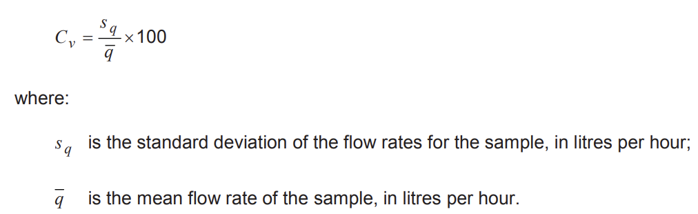
The mean flow rate of the test sample shall not deviate from the nominal flow rate, qn, by more than ± 7 %. The coefficient of variation, Cv, of the flow rate of the test sample shall not exceed 7 %.
9.1.3 Regulated emitters/emitting pipes
Condition the emitters/emitting units in the test sample by operating them for a total of 1 h. The conditioning
procedure shall consist of the following steps.
a) Set the minimum working pressure and maintain it for 3 min.
b) Set the maximum working pressure and maintain it for 3 min.
c) Set the minimum working pressure and maintain it for 3 min.
d) Set the maximum working pressure and maintain it for 3 min.
e) Set the minimum working pressure and maintain it for 3 min.
f) Set the maximum working pressure and maintain it for 3 min.
g) Set the pressure at the midpoint of the range of regulation and maintain it until the total time of the
conditioning procedure (1 h) is completed.
h) Immediately after conditioning and while maintaining the inlet pressure at the midpoint of the range of
regulation, test the emitters/emitting units according to 9.1.2.
The emitters/emitting units shall comply with the requirements of 9.1.2.
9.2 Flow rate as a function of inlet pressure
Perform the tests for determining flow rate as a function of inlet pressure as a continuation of the tests
performed in accordance with 9.1. When multiple emitters are tested, each outlet shall be considered as a
single emitter.
9.2.1 Test method
Test each emitter/emitting unit in steps not greater than 50 kPa, from zero pressure up to 1,2 pmax, such that at least four values of flow rates at four different pressures are obtained. Measure the flow rates at least 3 min after reaching the test pressure.
Test non-leakage emitters/emitting pipes in steps not greater than 10 kPa from zero pressure up to 0,5 pmax.
Starting from 0,5 pmax, continue raising the pressure in steps not exceeding 50 kPa.
Continue the tests of the regulated emitters/emitting units decreasing the pressure from 1,2 pmax to 0 in the same pressure values shall be used as when testing at rising pressures.
If the actual inlet pressure exceeds the desired inlet pressure by more than 10 kPa during its rise and fall,
return to zero pressure and repeat the test.
9.2.2 Unregulated emitters/emitting pipes
Calculate, for each pressure level, the average emission rate, q , in litres per hour, obtained by measuring the flow rates of the emitters/emitting units at rising pressure.
Plot the curve q as a function of inlet pressure. The curve of q shall conform to the curve presented in
manufacturers’ publications within an allowable deviation of not more than ± 7 %.
9.2.3 Regulated emitters/emitting pipes
Calculate, for each inlet pressure level, p, the average flow rate, q , obtained by measuring the flow rates of the emitters/emitting units at rising and falling pressure (the average of eight flow rate measurements).
The values of q shall not deviate from the nominal flow rate by more than ± 7 %.
For non-leakage emitters/emitting units, the pressure at which flow begins and the pressure at which the flow stops shall not vary by more than 20 % from the manufacturer’s declared pressure.
9.3 Determination of emitter/emitting unit exponent
The relation between the flow rate, q, in litres per hour, and the inlet pressure in an emitter/emitting unit, p, in kilopascals, is given by the formula:
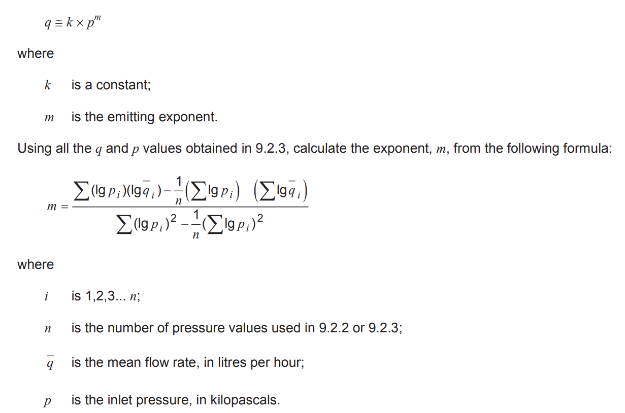
For regulated emitters/emitting pipes, the value of the emitting exponent, m, shall not exceed 0,2.
The calculated exponent shall not deviate from the manufacturer’s declaration by more than ± 5 %.
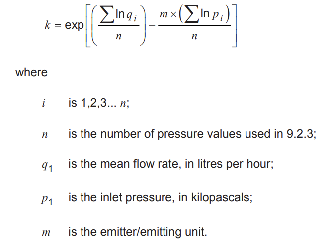
NOTE The emitter/emitting unit “constant”, k, can also be calculated by the following formula:
9.4 Dimensions
9.4.1 Wall thickness of emitting pipe
Measure the wall thickness using a measuring instrument having an accuracy of 0,01 mm. The measurement may be rounded to the nearest 0,05 mm.
Measure the wall thickness of the emitting pipe at four points equally spaced on the periphery of the pipe.
Repeat the test at two cross-sections. In the event of a part of the pipe wall being thicker by design (for
example, a flap in the emitting pipe), disregard such increased thickness.
The wall thickness of the emitting pipe, when measured individually at each of the four points, shall not be less than 90 % of the declared wall thickness.
9.4.2 Inside diameter of emitting pipe
Measure the inside diameter using a measuring instrument having an accuracy of 0,05 mm. The
measurement may be rounded to the nearest 0,1 mm.
To measure the inside diameter of the emitting pipe, insert a conical part (apex angle not greater than 10°) into the end of the emitting pipe, taking care not to enlarge the pipe diameter. Mark on the cone the circle made by the end of the pipe and measure its diameter.
Alternative measuring methods, such as calculation of the diameter by measuring the pipe circumference,
may be used.
The measured inside diameter shall not deviate by more than ± 0,3 mm from the declared diameter.
9.4.3 Spacing of emitting units
Measure three spacings of emitting units accurately to the nearest 1,0 mm.
The spacings of the emitting units shall not deviate by more than 5 % from the spacings declared by the
manufacturer.
9.5 Resistance to hydraulic pressure
9.5.1 Resistance to hydraulic pressure at ambient temperature, 23° ± 3 °C
Carry out the test on a length of pipe consisting of five emitters or five emitting units joined by means of in-line fittings.
Carry out the test in two stages (see 9.5.1.1 and 9.5.1.2).
9.5.1.1 Connect the assembly to a source of water (connecting the emitting pipe by means of an inlet
fitting) and close its outlet end. Fill the assembly with water and check that no air remains trapped in the pipe.
Increase the water pressure gradually (10 s minimum) to 1,2 pmax for non-reusable emitting pipes or to 1,8pmax for reusable emitting pipes and for emitters, and maintain the test pressure for 1 h.
The assembly shall withstand the test pressure without showing signs of damage to the emitters/emitting
pipes, the emitting units or the connecting fittings. The assembly shall not pull apart, and no leakage shall
occur at the inlet fitting. Leakages not exceeding the emission rate of one emitting unit are permissible at inline fittings.
9.5.1.2 Reduce the test pressure to the nominal test pressure and maintain it for at least 3 min. Measure
the flow rate of each emitter/emitting unit.
For emitters designed to enter a “flush mode” at high pressures to remove clogs, reduce the pressure to zero before measuring flow rate at the nominal pressure.
The flow rate of each emitter/emitting unit shall not deviate by more than ± 10 % from its original flow rate as measured in 9.1.
9.5.2 Resistance to hydraulic pressure at elevated temperature
Carry out the test on an assembly consisting of three emitters connected to a lateral or of three unit emitting pipes joined by means of in-line fittings.
9.5.2.1 Connect the assembly to a source of water by means of an inlet fitting and close its outlet end. Fill
the assembly with water and check that no air remains trapped in the pipe. Raise the water pressure gradually (10 s minimum) to the maximum working pressure and maintain the pressure for 1 h while the emitting pipe test assembly is immersed in water at 40 °C ± 3 °C.
The assembly shall withstand the test pressure without showing signs of damage.
9.5.2.2 Remove the test assembly from the water and leave it for 30 min at ambient temperature. Apply a
hydrostatic pressure, pn, for at least 3 min at 23 °C ± 3 °C and measure the flow rate of each emitting unit.
The flow rate of each emitter/emitting unit shall not deviate by more than ± 10 % from its original flow rate, as measured in 9.1.
9.6 Resistance to tension (emitting pipe)
Carry out the test at a temperature of 23 °C ± 3 °C.
If the emitting pipe is reusable, mark two lines, 150 mm apart, on the unit emitting pipe.
Fasten each unit emitting pipe in the grips of a tension-testing machine and uniformly increase (over 20 s to 30 s) the pull on the unit emitting pipe to
a) 160 N for non-reusable emitting pipes (see Clause 4.1.1), or
b) 180 N for reusable emitting pipes (see 4.1.2).
Notwithstanding this, if the manufacturer’s publications (see Clause 10) declare that the maximum permitted tension force is less than the abovementioned force, perform the test as specified here with the tension force declared by the manufacturer.
Maintain the tension force for 15 min, then release.
Non-reusable emitting pipes shall withstand the test tension force without breaking or tearing.
Reusable emitting pipes shall withstand the test tension force without breaking or tearing, the nominal flow rate in the test specimen shall not vary by more than ± 10 % from the flow rate measured before testing, and the distance between the two marked lines shall not vary by more than ± 5 % from the distance measured according to this subclause.
9.7 Resistance to pull-out of joints between fittings and polyethylene reusable emitting pipes
The test method and the test equipment used shall be as specified in ISO 3501, except that the test tension force shall be 180 N, applied for 15 min.
Notwithstanding the above, if the manufacturer’s publications (see Clause 10) declare that the maximum
permitted tension force is less than the abovementioned force, perform the test with the tension force declared by the manufacturer.
The fitting shall not pull out from the emitting pipe.
Where the emitting pipe is not made of polyethylene or the pipe wall is not uniform, this test may be performed in conjunction with the resistance to tension test in 9.6 by connecting between two sections of emitting pipe, each at least 300 mm long.
9.8 Emitter pull-out
Conduct this test at a temperature of 23 °C ± 3 °C, and with a type of pipe suitable for use with the emitter (see Clause 10).
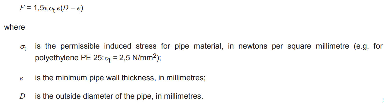
9.8.1 In-line emitters
Perform the test on three lengths of pipe (irrigation lateral), each containing one emitter. Gradually apply an axial tensile force to produce a pull-out force, F, in newtons, on the two lengths of pipe connected to the emitter, where F is calculated from the following formula and is not greater than 500 N:
Apply F for 1 h, with the emitter vertical, by means of a weight or the apparatus specified in ISO 3501.
Notwithstanding the above, if the manufacturer’s publications (see Clause 10) declare that the maximum
permitted tension force is less than the abovementioned force, perform the test as specified here with the
tension force declared by the manufacturer.
The emitters shall withstand the pull-out force, F, without the pipes pulling out.
Where the irrigation lateral is not made of polyethylene or the pipe wall is not uniform, this test may be
performed in conjunction with the resistance to tension test in 9.5 by connecting between two sections of pipe, each at least 300 mm long.
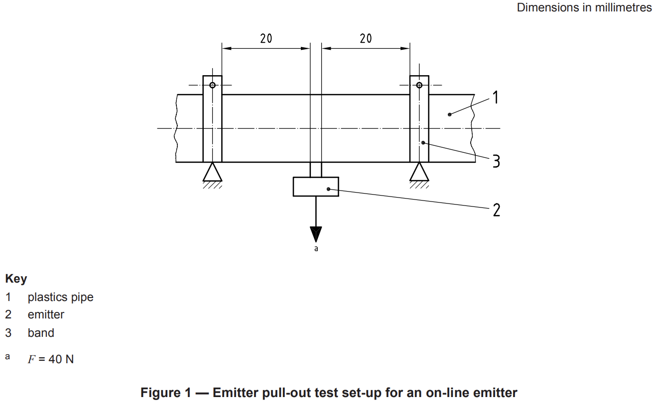
9.8.2 On-line emitters
Gradually apply a pulling force of 40 N on the emitter, perpendicular to the pipe, for 1 h (see Figure 1).
The emitter shall withstand the pulling force without pulling out of the pipe wall.
9.9 Watertightness of the emitter–pipe assembly
Connect five emitters to the pipe by the connection methods recommended by the manufacturer (see
Clause 10).
Connect one end of the emitter–pipe assembly to a source of hydraulic pressure and plug the other end of the assembly.
Perform the test on five emitters connected to a lateral at a temperature of 23 °C ± 3 °C.
Increase the pressure in three steps:
a) 5 min at 0,4 pmax;
b) 5 min at 0,8 pmax;
c) 60 min at 1,2 pmax.
No leakage shall occur through the emitter bodies or their connections to the pipe, except at points of emitter discharge.
9.10 Resistance of polyethylene (PE) emitting pipe to environmental stress-cracking Conduct the test in accordance with ISO 8796 and its requirements.
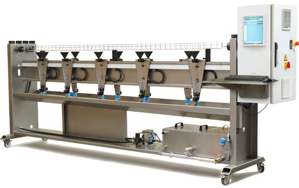
Drip Irrigation Pipes Quality Control Test Bench
- According to ISO 9261
- 10 precise measuring elements
- Closed-loop water system
- Temperature controlled water tank
- Automatic water level control of tank
- Tank and water touching elements made of SS304
- PLC based control
- Software is windows based and included
- The machine will be supplied with a wall mount computer or a Laptop
- Machine can perform several tests, such as flow at nominal pressure, flow at variable pressure and burst burst tests
- Pipe diameter 12-22mm
- Pipe wall thickness 0.125 – 1.20 mm
- Dripper flow range 0.4 – 8 L/h
- System pressure range 0.3 – 6 Bar
- Burst test is an option (Customer needs to ask for a quotation)