

4 Apparatus
4.1 Gripping device, capable of ensuring that the direction of the load applied to the test specimen
coincides as closely as possible with the longitudinal axis of the specimen. This ensures that the test specimen is subjected to simple stress and that the stresses in the loaded section of the specimen may be
assumed to be uniformly distributed over cross-sections perpendicular to the direction of the applied load.
It is recommended that grips be used that will allow the specimen to be fixed in place, correctly aligned, prior to applying the load. Self- locking grips which allow the specimen to move as the load increases are not suitable for this test.
4.2 Loading system, capable of ensuring that the load is applied smoothly, without causing transient
overloading, and that the load is maintained to within ± 1 % of the desired load. In creep -to -rupture tests, provision shall be made to prevent any shocks which occur at the moment of rupture being transmitted to adjacent loading systems. The loading mechanism shall allow rapid, smooth and reproducible loading.
4.3 Extension-measuring device, comprising any contactless or contact device capable of measuring
the extension of the specimen gauge length or the increase in the distance between the clamp grips under load without influencing the specimen behaviour by mechanical effects (e .g. undesirable deformations, notches), other physical effects (e .g. heating of the specimen) or chemical effects.
In the case of contactless (optical) measurement of the strain, the longitudinal axis of the specimen
shall be perpendicular to the optical axis of the measuring device. To determine the increase in length of the test specimen, an extensometer shall be used which records the increase in the distance between the clamp grips. The accuracy of the extension-measuring device shall be better than ± 0 ,01 mm .
For creep -to -rupture tests, it is recommended that the extension be measured by means of a contactless op tical system operating on the cathetometer principle. Automatic indication of time to rupture is highly desirable. The gauge length shall be marked on the specimen, either by attaching (metal) clips with scratched-on gauge marks, or by ruling the gauge marks with an inert, thermally stable paint. Electrical-resistance strain gauges are suitable only if the material tested is of such a nature as to permit such strain gauges to be attached to the specimen by means of adhesive and only if the adhesion quality is constant during the duration of the test. The modulus of the strain gauge when bonded to the specimen shall be such that the specimen is not reinforced.
4.4 Time-measurement device, accurate to 0 ,1 % .
4.5 Micrometer, reading to 0,01 mm or closer, for measuring the initial thickness and width of the test
specimen.
5 Test specimens
Use test specimens of the same shape and dimensions as specified for the determination of tensile
properties by the relevant material standard or, by default, as specified in ISO 527-2.
6 Procedure
6.1 Conditioning and test atmosphere
Condition the test specimens as specified in the International Standard for the material under test. In the absence of any information on conditioning, use the most appropriate set of conditions specified in ISO 291, unless otherwise agreed by the interested parties.
The creep behaviour will be affected not only by the thermal history of the specimen under test, but
also by the temperature and (where applicable) humidity used in conditioning (see ISO 10350 -1). I f the specimen is not in humidity equilibrium, creep will be affected in the following way: a specimen which is too dry will produce an additional strain due to water absorption during the test and a specimen which is too humid will contract due to water desorption. It is recommended that a conditioning time ≥ t90 (see ISO 62 ) be used.
Conduct the test in the same atmosphere as used for conditioning, unless otherwise agreed upon by
the interested parties, e .g., for testing at elevated or low temperatures. Ensure that the variation in
temperature during the duration of the test remains within ± 2 °C.
6.2 Measurement of test-specimen dimensions
Measure the dimensions of the conditioned test specimens in accordance with ISO 527-1 :2012 , 9 .2 .
6.3 Mounting the test specimens
Mount a conditioned and measured specimen in the grips and set up the extension-measuring device as required.
6.4 Selection of stress value
Select a stress value appropriate to the application envisaged for the material under test, and calculate, using the formula given in 3 .2 , the load to be applied to the test specimen.
If the initial strain is specified instead of the stress, the stress value may be calculated using tensile modulus for the material (see ISO 527-1).
6.5 Loading procedure
6.5.1 Preloading
When it is necessary to preload the test specimen prior to increasing the load to the test load, for
example in order to eliminate backlash by the test gear, take care to ensure that the preload does not
influence the test results. Do not apply the preload until the temperature and humidity of the test specimen (gripped in the test apparatus) correspond to the test conditions. Measure the gauge length
after application of the preload. Maintain the preload during the whole duration of the test.
6.5.2 Loading
Load the test specimen smoothly so that full loading of the specimen is reached between 1 s and 5 s
after the beginning of the application of the load. Use the same rate of loading for each of a series of
tests on one material.
Take the total load (including the preload) to be the test load.
6.6 Extension-measurement schedule
Record the point in time at which the specimen is fully loaded as t = 0. Unless the extens ion is
automatica l ly and/or continuous ly recorded, choose the times for making individual measurements as
a function of the creep curve obtained from the particular material under test. It is preferable to use the following measurement schedule:
1 min, 3 min, 6 min, 12 m in, and 30 m in ;
1 h , 2 h , 5 h , 10 h , 20 h , 50 h , 100 h , 200 h , 500 h , 1 000 h , etc .
If discontinuities are suspected or observed in the creep-strain versus time plot, take readings more
frequently.
6.7 Time measurement
Measure, to within ±0.1 % or ± 2 s (whichever is the less severe tolerance), the total time which has
elapsed up to each creep measurement.
6 .8 Temperature and humidity control
Unless temperature and relative humidity (where applicable) are recorded automatically, record them at the beginning of the test and then at least three times a day initially. When it has become evident that the conditions are stable within the specified limits, they may be checked less frequently (but at least once a day).
6 .9 Measurement of recovery rate (optional)
Upon completion of non-rupture tests, remove the load rapidly and smoothly and measure the recovery rate using, for instance, the same schedule as was used for creep measurement.
7 Expression of results
7.1 Method of calculation
7.1.1 Tensile-creep modulus, Et
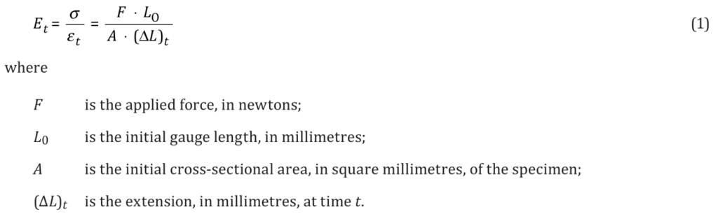
Calculate the tensile-creep modulus, Et, by dividing the initial stress, σ, by the tensile-creep strain, εt, at each of the selected measurement times.
It is given, in megapascals, by Formula (1) :
7.1.2 Nominal tensile-creep modulus, Et
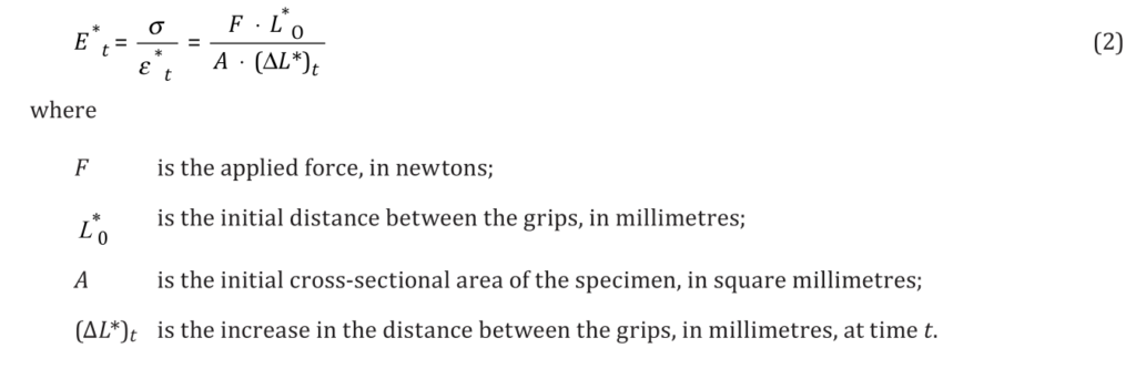
Calculate the nominal tensile-creep modulus, Et, by dividing the initial stress, σ, by the nominal tensile-creep strain, ε*t, at each of the selected measurement times.
It is given , in megapascals , by Formula (2 ) :
7.2 Presentation of results
7.2.1 Creep curves
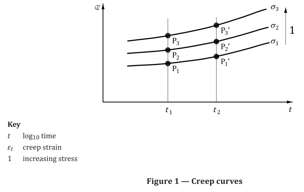
If testing is carried out at different temperatures, the raw data should preferably be presented, for each temperature, as a series of creep curves showing the tens i le s train p lotted aga ins t the logarithm of time, one curve being plotted for each initial stress used (see Figure 1).
7.2.2 Creep -modulus/time curves
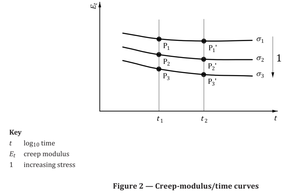
For each initial stress used, the tensile-creep modulus, calculated in accordance with 7.1 .1, may be
plotted against the logarithm of the time under load (see Figure 2).
If testing is carried out at different temperatures, plot a series of curves for each temperature.
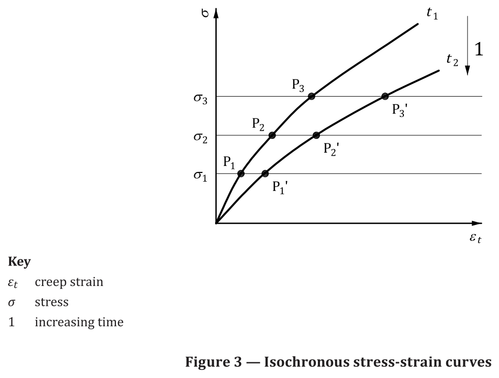
7.2.3 Isochronous stress-strain curves
An isochronous stress-strain curve is a Cartesian plot showing how the strain depends on the applied load, at a specific point in time after application of the load. Several curves are normally plotted, corresponding to times under load of 1 h, 10 h, 100 h, 1 000 h and 10 000 h. Since each creep test gives only one point on each curve, it is necessary to carry out the test at, at leas t, three different stresses, and preferably more, to obtain an isochronous curve (see ISO 11403 -1).
To obtain an isochronous stress-strain curve for a particular time under load (say 10 h) from a series
of creep curves as shown in Figure 1, read off, from each creep curve, the strain at 10 h, and plot these strain values (x-axis) against the corresponding s tress values ( y-axis). Repeat the process for other
times to obtain a series of isochronous curves (see Figure 3).
If testing is carried out at different temperatures, plot a series of curves for each temperature.
Objective of creep tests on plastics
- During a creep test, specimens are subjected to a static load. This corresponds to the load applied on many components made of plastic. The specimen strain is recorded over a long time of test period, which often lasts 1,000 hours. Using this data, creep curves can be generated, which depict the long-term behavior of plastics.
- Creep tests on plastics are described in the following standards: ISO 899-1 and ISO 899-2, as well as ASTM D2990. A full notch creep test (FNCT) to ISO 16770 is used to test pipes.
- Since this type of test runs over a long period of time, it is typical to test multiple specimens at once.
- Conditioning is an important part of the test. It is necessary to prevent thermal expansion due to temperature fluctuations, which overlap the creep strain. For this reason, it is necessary to ensure that the environmental conditions remain constant throughout the test. For tests outside of the ambient temperature, accurately controlled temperature chambers are used. For this, we have different options for testing at laboratory room temperature and other temperature ranges according to the customer’s request.
- The specimen strain is determined optically by modern creep test systems that use a high-precision video measurement system or by linear transducers.
- Constant force application is done either by a lever mechanism or by a pneumatic cylinder system.
- A controlled test environment (in terms of temperature and humidity) is an option and will be provided according to the customer’s request.

Tensile Creep Tester According to ISO 899-1
- Force range: According to customer request
- Computerized model
- Automatic calculation of test results by a Windows based software
- Monitoring of force and displacement data during the whole test time
- Database for long-term test data saving
- Force application is either by a pneumatic cylinder or by a lever mechanism and dead weight
- Different grips for different test samples and thicknesses are available
- The number of stations will be as per the customer’s request
- An economic model of one load cell for one-time force measurement on all test stations at startup is available (On this model, only the data for displacement on all stations will be recorded in the whole test time period)