
4 Principle
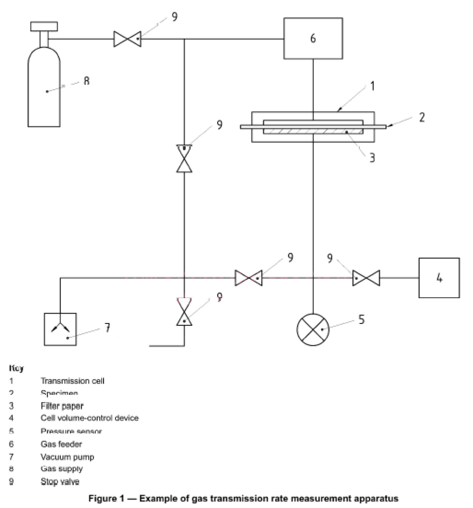
A test specimen is mounted in a gas transmission cell (see Figure I) so as to form a sealed barrier between two chambers. The lower-pressure chamber is evacuated, followed by evacuation of the higher-pressure chamber. A gas is introduced into the evacuated higher-pressure chamber and permeates into the lower-pressure chamber. The permeation of gas through the specimen is indicated by an increase in pressure on the lower-pressure side.
5 Test specimens
5.1 Test specimens shall be representative of the material under investigation, free from shrivelling, folds and pinholes, and of uniform thickness. They shall be larger than the gas transmission area of the measurement cell and be capable of being mounted airtight.
5.2 Use three specimens unless otherwise specified or agreed upon among the interested parties.
5.3 Mark the side of the material facing the permeating gas.
NOTE In principle, the test should replicate the actual conditions of use, with the gas passing from the inside to the outside of e.g. packaging material, or vice versa.
5.4 Measure the thickness of each specimen in accordance with ISO 4593, to the nearest 1 µm, at at least five points distributed over the entire test area, and record the minimum, maximum and average values.
6 Conditioning and test temperature
6.1 Conditioning
Dry the specimens for not less than 48 h at the same temperature as that at which the test is to be carried out, using calcium chloride or another suitable drying agent in a desiccator. Drying will not normally be required for non-hygroscopic materials.
6.2 Test temperature
Carry out the test in a room kept at 23 °C ± 2 °C, unless otherwise specified.
7 Apparatus and materials
7.1 General
Figure 1 shows an example of an apparatus for determining gas transmission rate.
The apparatus consists of a gas transmission cell designed to allow a gas to permeate through a specimen, a pressure sensor to detect the pressure change due to the permeation of the gas through the specimen, a gas feeder to supply the gas to the transmission cell, a cell volume-control device and a vacuum pump.
7.2 Transmission cell
The transmission cell shall consist of an upper (high-pressure) chamber and a lower (low-pressure) chamber, designed so that the gas transmission area is constant for any specimen mounted in the cell. The high-pressure chamber shall have an inlet for the gas and the low-pressure chamber shall be connected to a pressure sensor. The surfaces in contact with the specimen shall be smooth and flat so that leakage does not occur. The diameter of the gas transmission area shall be 10 mm to 150 mm.
7.3 Pressure sensor
The sensor shall be capable of determining the change in pressure on the low-pressure side with a minimum sensitivity of 5 Pa (0,038 mmHg). A vacuum gauge with no mercury, an electronic diaphragm-type sensor or another suitable type shall be used.
7.4 Gas feeder
The gas feeder is basically a reservoir designed to store the gas. The gas is fed to the high-pressure side of the cell from the feeder. In order to determine the pressure in the reservoir, a manometer with a minimum sensitivity of
100 Pa (0,75 mmHg) is fitted. The reservoir shall have sufficient capacity such that permeation of the gas through the specimen does not cause any drop in pressure on the high-pressure side
7.5 Cell volume-control device
In order to extend the transmission rate measurement range, the volume of the low-pressure chamber may be adjusted by a cell volume-control device such as an additional reservoir or an adapter.
7.6 Gas
The gas used should preferably have a purity as specified by a relevant International Standard or other suitable standard. The use of gases of other purities shall be subject to agreement between the interested parties.
7.7 Vacuum pump
A vacuum pump capable of producing a vacuum better than 10 Pa (0,075 mmHg) in the low-pressure chamber shall be used.
8 Procedure
8.1 Spread a filter paper having the same size as the gas transmission area in the low-pressure chamber.
NOTE The filter paper is used to support the specimen film. A filter paper of the type generally used for chemical analysis, of thickness about 0,2 mm to 0,3 mm, is recommended for this purpose.
8.2 Coat the flat edges of the two halves of the transmission cell thinly and uniformly with vacuum grease, and mount the specimen over the lower chamber so that no creasing or slackness occurs.
8.3 Place a rubber sealing ring on the specimen, followed by the upper part of the cell, pressing down with uniform pressure so that the specimen is completely sealed in place.
8.4 Start the vacuum pump. Air will be evacuated first from the low-pressure side, followed by the high-pressure side.
8.5 When all air has been evacuated, stop the vacuum pump, shutting off the relevant valve to maintain the vacuum. Care is necessary here, because the time taken to completely exhaust the cell will depend on the permeability of the specimen.
8.6 If the pressure on the low-pressure side rises, repeat 8.3 to 8.5 to ensure that no air is leaking into the cell and to complete any degassing.
8.7 Introduce the gas into the high-pressure side, shutting off the gas supply when a pressure of about one atmosphere has been reached. Record the pressure p, on the high-pressure side as indicated by the manometer associated with the gas feeder. An increase in pressure on the low-pressure side will confirm transmission of the gas.
8.8 Plot a curve of the pressure on the low-pressure side versus time, continuing until equilibrium has been reached as indicated by a straight line.
8.9 Determine the slope of the straight-line portion of the transmission curve (dp/dt, see clause 9). An automatically recorded transmission curve may also be used.
9 Calculation
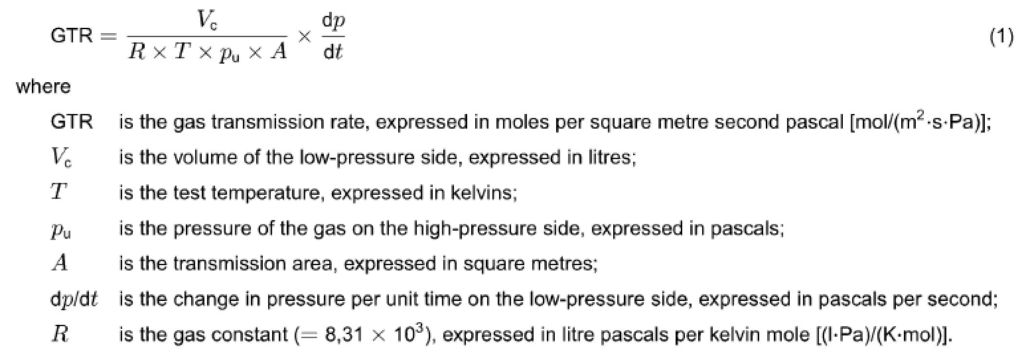
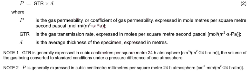
Calculate the gas transmission rate and the gas permeability, or coefficient of gas permeability, from equations (I) and (2).
a) Gas transmission rate
b) Gas permeability, or coefficient of gas permeability
10 Test results
Calculate the arithmetic mean of the results obtained for all the specimens, rounding to three significant figures.
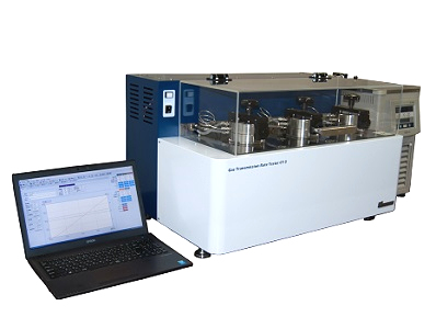
Gas Transmission Rate Tester According to ISO 15105-1 / Single Station
- Number of specimen: 1
- Temperature range: Room temperature
- Dimensions of specimen: 50 × 50mm(measuring cell: ∅30mm, transmission area: 707mm²)// 90 × 90mm(measuring cell: ∅70mm, transmission area: 3848mm²
- GTR measurement range (To be selected type A or B upon order): Type A: 4.5×10⁻¹⁵〜4.5×10¹² [mol/(m2・s・Pa)](0.1 〜100[fm/(Pa・s)])// Type B: 4.5×10⁻¹⁴〜4.5×10⁻¹¹ [mol/(m2・s・Pa)](1 〜1000[fm/(Pa・s)])
- Test gas: Oxygen, Nitogen, Carbon dioxide, Air, Hydrogen (Optional) etc.
- Test gas pressure: 0 to 200kPa
- Measurement items: Gas transmission rate, Gas transmission coefficient
- Software is included
- Automatic calculation of GTR
- European pressure sensors are used
- Automatic solenoid valves are used
- Vacuum pump is included
- The connection port to the computer is USB
- Computer is as option
- High sensitivity vacuum pressure gauge of reading accuracy 0.25% is employed
- Specimen table supports two different sizes of specimen
- Many kinds of gases can be measured
- Online installation and training of the software