
7 Test equipment
7.1 General
The equipment used for all measurements shall be traceable to national or International Standards. They shall be calibrated within suitable intervals.
7.2 Installation and verification
The testing machine shall be installed and verified in accordance with ISO 148-2.
7.3 Striker
The striker geometry shall be specified as being either the 2 mm striker or the 8 mm striker. It is
recommended that the striker radius be shown as a subscript as follows: KV2 or KV8.
Reference shall be made to the product specification for striker geometry guidance.
NOTE Some materials can yield significantly varying results (percent difference) at low energy levels and the 2 mm results can be higher than the 8 mm results.
8 Test procedure
8.1 General
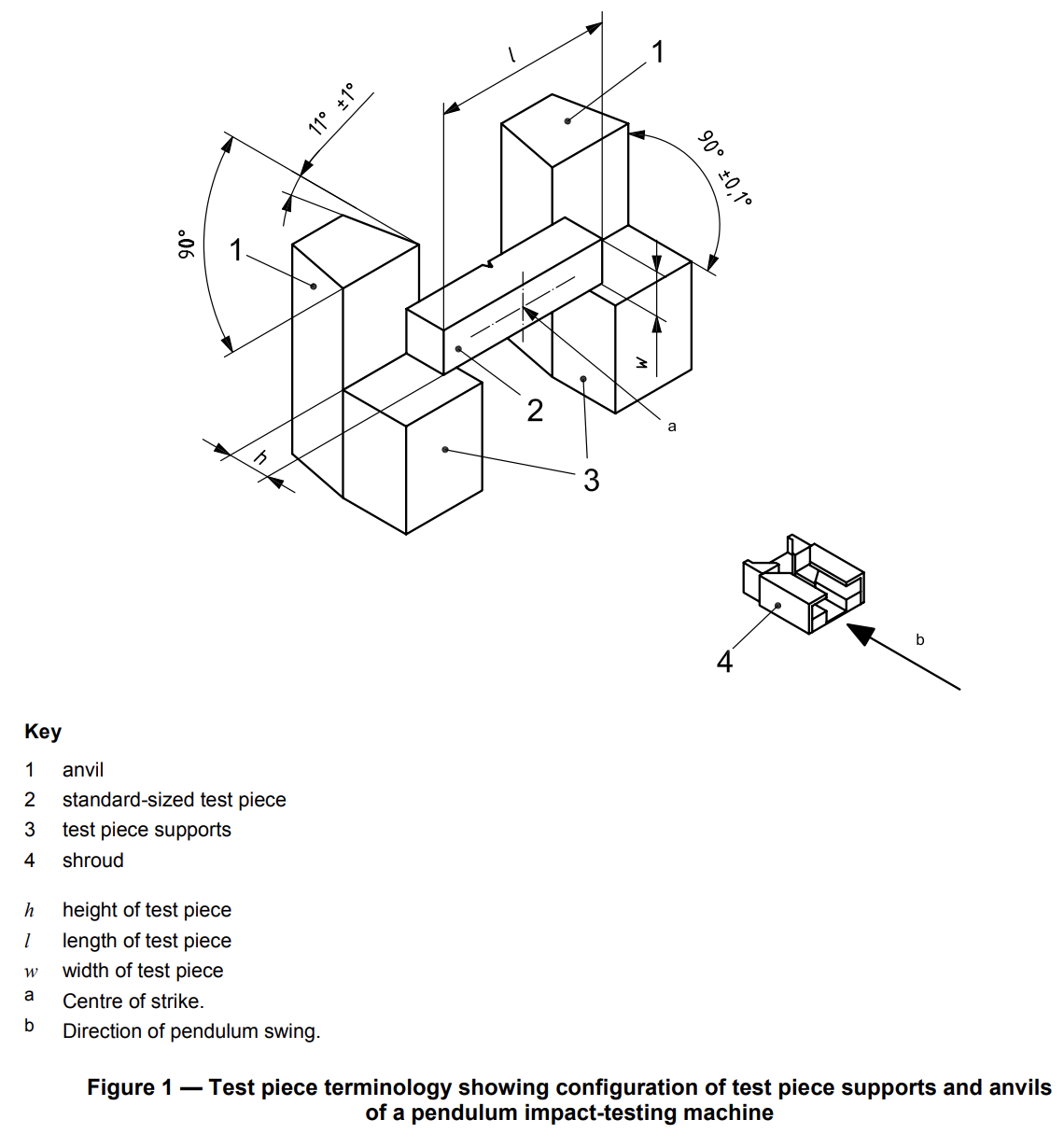
The test piece shall lie squarely against the anvils of the testing machine, with the plane of symmetry of the notch within 0,5 mm of the midplane between the anvils. It shall be struck by the striker in the plane of symmetry of the notch and on the side opposite the notch (see Figure 1).
8.2 Test temperature
8.2.1 Unless otherwise specified, tests shall be carried out at (23 ± 5) °C. If a temperature is specified, the
test piece shall be conditioned to that temperature to within ± 2 °C.
8.2.2 For conditioning, either heating or cooling, using a liquid medium, the test piece shall be positioned in a container on a grid that is at least 25 mm above the bottom of the container and covered by at least 25 mm of liquid and be at least 10 mm from the sides of the container. The medium shall be constantly agitated and brought to the specified temperature by any convenient method. The device used to measure the temperature of the medium should be placed in the center of the group of test pieces. The temperature of the medium shall be held at the specified temperature to within ± 1 °C for at least 5 min.
NOTE When a liquid medium is near its boiling point, evaporative cooling can dramatically lower the temperature of the test piece during the interval between removal from the liquid and fracture (see ASTM STP 1072).
8.2.3 For conditioning, either heating or cooling, using a gaseous medium, the test piece shall be positioned in a chamber at least 50 mm from the nearest surface. Individual test pieces shall be separated by at least 10 mm. The medium shall be constantly circulated and brought to the specified temperature by any convenient method. The device used to measure the temperature of the medium should be placed in the center of the group of test pieces. The temperature of the gaseous medium shall be held at the specified temperature within ± 1 °C for at least 30 min
8.3 Specimen transfer
When testing is performed at other than ambient temperature, not more than 5 s shall pass between the time the test piece is removed from the heating or cooling medium and the time it is struck by the striker.
The transfer device shall be designed and used in such a way that the temperature of the test piece is
maintained within the permitted temperature range.
The parts of the device in contact with the specimen during transfer from the medium to the machine shall be conditioned with the specimens.
Care should be taken to ensure that the device used to center the test piece on the anvils does not cause the fractured ends of low-energy, high-strength test pieces to rebound off this device into the pendulum and cause erroneously-high indicated energy. It has been shown that clearance between the end of a test piece in the test position and the centring device, or a fixed portion of the machine, shall be greater than approximately 13 mm or else, as part of the fracture process, the ends can rebound into the pendulum.
NOTE Self-centring tongs, similar to those for V-notched test pieces in Annex A, are often used to transfer the test piece from the temperature-conditioning medium to the proper test position. Tongs of this nature eliminate potential clearance problems due to interference between the fractured specimen halves and a fixed centring device.
8.4 Exceeding machine capacity
The absorbed energy, K, should not exceed 80 % of the initial potential energy, Kp. If the absorbed energy
exceeds this value, the absorbed energy shall be reported as approximate and it shall be noted in the test
report that it exceeded 80 % of the machine capacity.
NOTE Ideally, an impact test would be conducted at a constant impact velocity. In a pendulum-type test, the velocity decreases as the fracture progresses. For specimens with impact energies approaching the capacity of the pendulum, the velocity of the pendulum decreases during fracture to the point that accurate impact energies are no longer obtained.
8.5 Incomplete fracture
If a test piece is not completely broken in a test, the impact energy may be reported or averaged with the
results of the completely broken test pieces.
8.6 Test piece jamming
If any test piece jams in the machine, the results shall be disregarded and the machine thoroughly checked for damage that would affect its calibration.
NOTE Jamming occurs when a broken test piece is caught between moving and non-moving parts of the testing machine. It can result in significant energy absorption. Jamming can be differentiated from secondary strike marks, because a jam is associated with a pair of opposing marks on the specimen.
8.7 Post-fracture inspection
If post-fracture inspection shows that any portion of the marking is in a portion of the test piece which is visibly deformed, the test result might not be representative of the material and this shall be noted in the test report.


300J Charpy Impact Tester
- Suitable for Charpy Impact Tests on various materials
- Rigid designs of machine frame and other parts assure minimum energy absorption during fracture
- The highly stressed and wearing parts like support blocks and strikers are of special alloy steels duly heat treated
- Works on pendulum principle, difference between height of drop of pendulum before rupture and height of rise after rupture of specimen is directly proportional to impact energy absorbed
- Direct indication of impact energy absorbed by specimen
- Touch display
- Thermal printer included for report printout
- USB data output port for exporting test data to MS Excel
- 10*10mm specimen support block is included
- Includes specimen setting gage
- Charpy striker of 300J energy capacity is included
- Pendulum drop angle 140 degrees
- Impact velocity 5.2 m/s
- Distance between axis of rotation and center of strike 813.5mm
- Effective weight of striker 21.3Kg
- Striker angle at tip 30 degrees
- Radius of curvature 2mm
- Width of tip 18mm
- Distance between supports 40mm
- Taper of supports 11 degrees
- Radius of curvature at edge of supports 1-1.5mm
- Approximate weight 430Kg
- Approximate dimensions(mm) 750 (L) X 500 (W) X 1850 (H)