
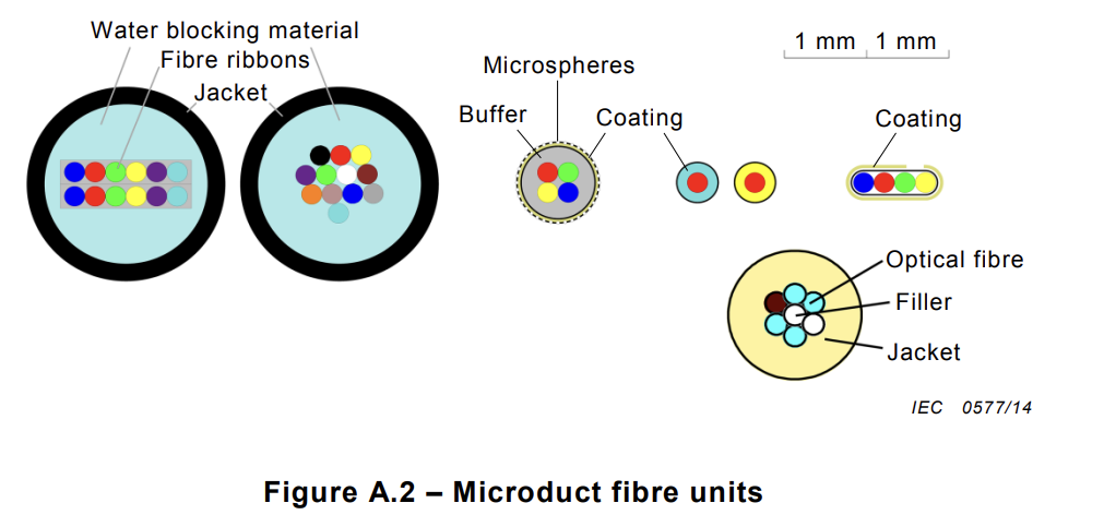
Figure A.1 and Figure A.2 give useful examples of microduct fibre units, microducts, and protected microducts.

5 Microduct fibre unit
5.1 Tests applicable
Tests that are applicable for mechanical and environmental performance are given in Table 2.
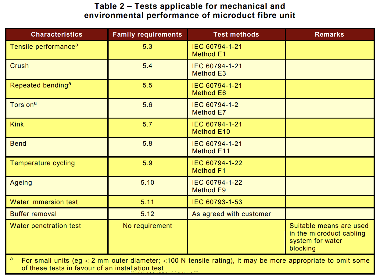
The above tests may need to be modified for use with these cables. In particular, special care needs to be taken when clamping cables in order to avoid end effects. Unacceptable damage may include rips, tears, splits, delamination or cracks in the microduct fibre unit. However, damage at the clamping interface does not constitute a failure.
5.2 Family requirements and test conditions for microduct fibre unit tests Tests shall be selected from the following by the product specification.
5.3 Tensile performance
a) Family requirements Under short-term tensile load the fibre strain shall not exceed 60 % of the fibre proof strain. Other criteria may be agreed between the customer and supplier.
b) Test conditions (loads ≥ 100 N)
Method: Generally to IEC 60794-1-21 Method E1, with duration as stated below
Length under tension: Not less than 10 m. Taking into account the measurement accuracy and end effects, shorter lengths may be used by agreement between the customer and supplier.
Fibre length: Finished microduct fibre unit length.
Tensile load: Equivalent to weight of 1 km of fibre unit
Duration of load 1 min
Diameter of test pulleys: As agreed between customer and supplier but not less than the minimum loaded bending diameter specified for the microduct fibre unit. A minimum value of 60 mm is recommended.
Under visual examination without magnification there shall be no damage to the microduct fibre unit and there shall be no change in attenuation after the test.
c) Test conditions (loads < 100 N)
Apparatus: Vertical tensometer
Length under tension: Approx 250 mm.
Fibre length: Finished microduct fibre unit length.
Tensile load: Equivalent to weight of 1 km of fibre unit
Duration of load 1 min
Under visual examination without magnification there shall be no damage to the microduct fibre unit.
5.4 Crush
a) Family requirements
After removal of the load, there shall be no change in attenuation compared to before the application of the load. Under visual examination, there shall be no damage to the microduct fibre unit . The imprint of the plate on the microduct fibre unit is not considered mechanical damage.
b) Test conditions
Method: IEC 60794-1-21 Method E3
Load (plate/plate): 100 N
Duration of load: 1 min
5.5 Repeated bending
a) Family requirements
Under visual examination without magnification there shall be no damage to the microduct fibre unit elements.
b) Test conditions
Method: IEC 60794-1-21 Method E6
Bending diameter: 40 × d or 60 mm whichever is greater.
Load: Adequate to assure uniform contact with the mandrel.
Number of cycles: 25
5.6 Torsion
a) Family requirements
Under visual examination without magnification there shall be no damage to the microduct fibre unit elements.
There shall be no change in attenuation after the test.
b) Test conditions
Method Generally in accordance with IEC 60794-1-21 Method E7
Test length: 300 mm
Load: Adequate to assure test sample is straight at start of test.
5.7 Kink
a) Family requirements
Under visual examination, there shall be no damage to the microduct fibre unit
b) Test conditions
Method: IEC 60794-1-21 Method E10
Minimum diameter: 40 × d or 60 mm whichever is greater
5.8 Bend
a) Family requirements
There shall be no change in attenuation after the test when measured at room temperature.
b) Test conditions
Method: IEC 60794-1-21 Method E11A
Diameter of mandrel: 40 × d or 60 mm whichever is greater
Number of turns/helix: 4
Number of cycles: 3
5.9 Temperature cycling
a) Family requirements
For TA1 to TB1 there shall be no change in attenuation as defined in IEC 60794-1-1.
For TA1 to TA2 and TB1 to TB2, the change in attenuation coefficient shall be:
– ≤ 0,15 dB/km for single-mode fibre and shall be reversible to measurement uncertainty
when measured in the 1 550 nm region;
– ≤ 0,3 dB/km for multimode fibre and shall be reversible to measurement uncertainty
when measured in the 1 300 nm region.
b) Test conditions
Method: IEC 60794-1-22 Method F1.
Sample length under test: Finished microduct fibre unit length of at least 1 000 m.
High temperature, TB2: +60 °C to +70 °C, depending on customer requirements.
High temperature, TB1: +30 °C to +60 °C depending on customer requirements.
Low temperature, TA1: –15 °C.
Low temperature, TA2: TA1 to –30 °C or –40 °C depending on customer requirements
Note (temperatures): Other temperature values corresponding to specific climate
conditions can be agreed between supplier and customer.
Number of cycles: 2
5.10 Ageing
a) Family requirements: as per IEC 60794-1-22, Method F9
b) Test conditions:
Method: IEC 60794-1-22, Method F9
5.11 Water immersion
a) Family requirements
Attenuation coefficient change at room temperature:
– ≤ 0,05 dB/km at 1 550 nm for single-mode fibre;
– ≤ 0,2 dB/km at 850 nm and 1 300 nm for multimode fibre.
The attenuation shall be monitored throughout the test at least once every 24 h.
b) Test conditions
Method: IEC 60793-1-53
Water: Distilled, demineralized or de-ionized water which has a PH
of between 5,0 and 8,0
Dwell time: 30 days
5.12 Buffer removal
a) Family requirements
The buffer materials shall be removable such that primary coated fibres or fibre ribbons shall be free from fibre unit sheathing and/or buffer materials and free from damage following the test.
b) Test conditions
The method for buffer removal shall be defined by the supplier.
6 Microduct
6.1 Tests applicable
Tests shall be selected from the following Table 3, in accordance with the relevant product specification. If the microduct is only to be used in a protected microduct, some tests may not be relevant.
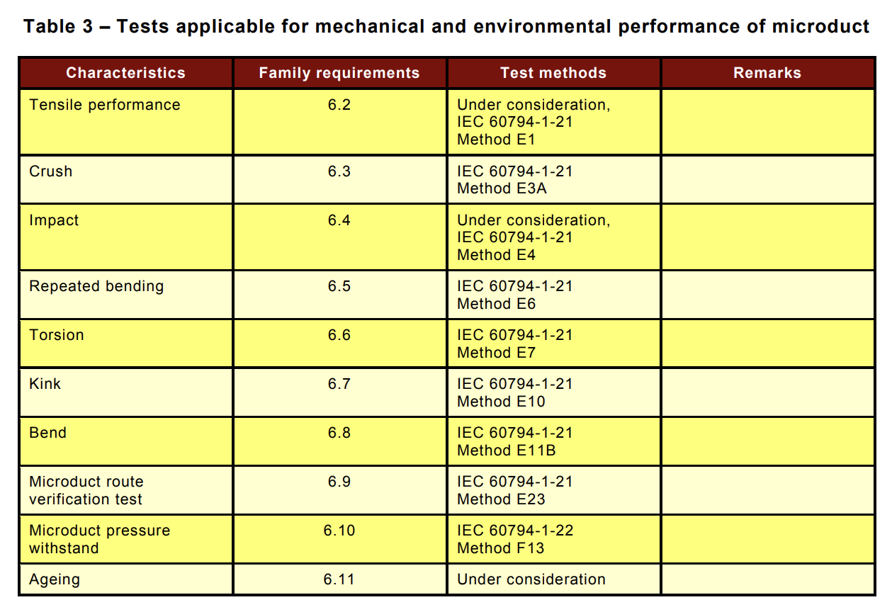
The above tests may need to be modified for use with microducts. In particular, special care needs to be taken when clamping in order to avoid end effects. Unacceptable damage may include rips, tears, splits or cracks in the microduct. However, damage at the clamping interface does not constitute a failure.
6.2 Tensile performance
a) Family requirements
Under visual examination, without magnification, there shall be no damage after the test
and shall pass the inner clearance test (Annex E).
b) Test conditions
Method: Generally to IEC 60794-1-21, Method E1
(note: use of IEC 60811-501 is under consideration)
Microduct length under tension: >1 m
Tensile load on microduct: 1 W
Duration of load: 10 min
6.3 Crush
a) Family requirements
Under visual examination, without magnification, the microduct shall show no damage. After the recovery time the microduct shall pass the inner clearance test (Annex E) and there shall be no splitting or permanent damage. The imprint of the plate is not considered as mechanical damage.
b) Test conditions
Method: IEC 60794-1-21, Method E3A
Load (plate/plate): 500 N
Duration time: 1 min
Recovery time 1h
6.4 Impact
a) Family requirements
Under visual examination without magnification there shall be no damage to the microducts. The microduct shall pass the inner clearance test (Annex E) and there shall be no splitting or permanent damage. The imprint of the striking surface on the microduct is not considered mechanical damage.
b) Test conditions
Method: IEC 60794-1-21 Method E4
Striking surface radius: 300 mm
Impact energy: 1 J
Recovery time: 1 h
Number of impacts: One in 3 different places spread not less than 500 mm apart
6.5 Repeated bending
a) Family requirements
Under visual examination without magnification there shall be no damage to the microducts. The microduct shall pass the inner clearance test (Annex E) and there shall be no splitting or permanent damage.
b) Test conditions
Method: IEC 60794-1-21 Method E6
Bending diameter: 40 × OD
Load: Adequate to assure uniform contact with the mandrel
Number of cycles: 25
6.6 Torsion
a) Family requirements
Under consideration
b) Test conditions
Method: IEC 60794-1-21 Method E7
Maximum gauge length: 2 m
6.7 Kink
a) Family requirements
Under visual examination, without magnification, there shall be no damage to the microducts after the test and shall pass the inner clearance test (Annex E). The microduct shall attain the required minimum diameter without kinking.
b) Test conditions
Method: IEC 60794-1-21 Method E10
Minimum diameter: 20 × OD
6.8 Bend
a) Family requirements
The outer and inner diameter of the microducts shall show, under visual examination without magnification, no damage and after the test and shall pass the inner clearance test (Annex E).
b) Test conditions
Method: IEC 60794-1-21 Method E11B
6.8 Bend
a) Family requirements
The outer and inner diameter of the microducts shall show, under visual examination without magnification, no damage and after the test and shall pass the inner clearance test (Annex E).
b) Test conditions
Method: IEC 60794-1-21 Method E11B
6.8 Bend
a) Family requirements
The outer and inner diameter of the microducts shall show, under visual examination without magnification, no damage and after the test and shall pass the inner clearance test (Annex E).
b) Test conditions
Method: IEC 60794-1-21 Method E11B
Diameter of mandrel: 40 × OD
Number of cycles: 3
6.9 Microduct route verification test
a) Family requirements
Objects of the required size, including any blowing tip if used in practice, can be passed through the microduct.
b) Test conditions
Method: IEC 60794-1-21 Method E23
6.10 Microduct pressure withstand
a) Family requirements
Under visual examination, without magnification, there shall be no damage to the
microducts.
b) Test conditions
Method: IEC 60794-1-22 Method F13
All microducts shall resist an air pressure of at least 2,5 × the installation pressure at a
temperature of 20 °C for a period of 0,5 h.
All microducts shall resist a proof test pressure of at least 1,3 × the installation pressure at a
temperature of 40 °C for a period of 24 h.
6.11 Ageing
a) Family requirements
Under consideration
Tests to be performed after the aging period should be agreed between the customer and supplier and could include dimensions, inner clearance test, shrinkage, changes to surface finish, pressurization or installation test of the microduct fibre unit.
b) Test conditions
Method: Under consideration
Aging condition: Under consideration (+60 °C for 3 months;
7 days at 70 °C; 7 days at 85 °C)
7 Protected microducts
7.1 Tests applicable
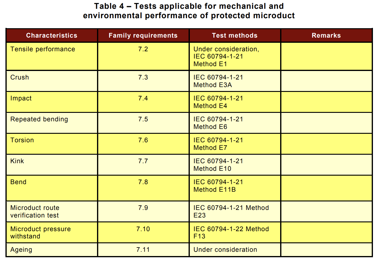
Tests shall be selected from the following Table 4, in accordance with the relevant product specification.
7.2 Tensile performance
a) Family requirements
Under visual examination, without magnification, there shall be no damage after the test and shall pass the inner clearance test (Annex E).
b) Test conditions
Method: Generally to IEC 60794-1-21 Method E1 (note: use of
IEC 60811-501 is under consideration)
Microduct length under tension: >1 m
Tensile load on microduct: 1 W or 2 700 N, whichever is the smaller
Duration of load: 10 min
7.3 Crush
a) Family requirements
Under visual examination, without magnification, the microduct shall show no damage. After the recovery time the microduct shall pass the inner clearance test (Annex E) and there shall be no splitting or permanent damage. The imprint of the plate is not considered as mechanical damage.
b) Test conditions
Method: IEC 60794-1-21 Method E3A
Sample length: 250 mm
Load: 1 kN (duct); 2 kN (buried)
Duration time: 1 min
Recovery time: 1 h
7.4 Impact
a) Family requirements
Under visual examination without magnification there shall be no damage to the microducts. The microduct shall pass the inner clearance test (Annex E) and there shall be no splitting or permanent damage. The imprint of the striking surface on the microduct is not considered mechanical damage.
b) Test conditions
Method: IEC 60794-1-21 Method E4
Striking surface radius: 300 mm
Impact energy: 3 J (duct); 15 J (buried)
Recovery time: 1 h
Number of impacts: One in 3 different places spread not less than 500 mm apart
7.5 Repeated bending
a) Family requirements
Under visual examination without magnification there shall be no damage to the microducts. The microduct shall pass the inner clearance test (Annex E) and there shall be no splitting or permanent damage.
b) Test conditions
Method: IEC 60794-1-21 Method E6
Bending diameter: 40 × OD
Load: Adequate to assure uniform contact with the mandrel
Number of cycles: 25
7.6 Kink
a) Family requirements
Under visual examination, without magnification, there shall be no damage to the microducts after the test and shall pass the inner clearance test (Annex E). The microduct shall attain the required minimum diameter without kinking.
b) Test conditions
Method: IEC 60794-1-21 Method E10
Minimum diameter: 20 × OD
7.7 Bend
a) Family requirements
The outer and inner diameter of the microducts shall show, under visual examination without magnification, no damage and after the test and shall pass the inner clearance test (Annex E).
b) Test conditions
Method: IEC 60794-1-21 Method E11B
Diameter of mandrel: 40 × OD
Number of cycles: 3
7.8 Microduct route verification test
a) Family requirements
Objects of the required size, including any blowing tip if used in practice, can be passed
through the microduct.
b) Test conditions
Method: IEC 60794-1-21 Method E23
7.9 Microduct pressure withstand
a) Family requirements
Under visual examination, without magnification, there shall be no damage to the microducts.
b) Test conditions
Method: IEC 60794-1-22 Method F13
All microducts shall resist an air pressure of at least 2,5 × the installation pressure at a
temperature of 20 °C for a period of 0,5 h.
All microducts shall resist a proof test pressure of at least 1,3 × the installation pressure at a
temperature of 40 °C for a period of 24 h.
7.10 Ageing
a) Family requirements
Under consideration
Tests to be performed after the aging period should be agreed between the customer and supplier and could include dimensions, inner clearance test, shrinkage, changes to surface finish, pressurization or installation test of the microduct fibre unit.
b) Test conditions
Method: Under consideration
Aging condition: Under consideration (+60 °C for 3 months; 7 days at 70 °C; 7 days at 85 °C)