
6 Method E4: Impact
6.1 Object
The purpose of this test is to determine the ability of an optical fibre cable to withstand
impact.
6.2 Sample
6.2.1 Sample length
The sample length shall be sufficient to carry out the specified test. When only physical
damage is to be evaluated, the length may range from 1 m (for example for small diameter
jumper cords or duplex cables) to 5 m (for larger diameter cables). Longer lengths may be
necessary to permit optical measurements.
6.2.2 Termination
The sample shall be terminated at each end in a connector, or in a manner such that the
fibres, sheathings and any strain members are clamped together in a representative manner.
Clamps on the impact apparatus may be used, or the sample may be long enough so that no
restraint is needed.
6.3 Apparatus
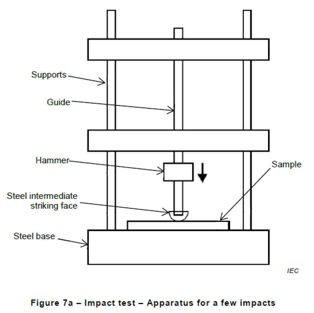
The apparatus shall allow an impact to be imparted to the cable sample which is fixed to a flat
substantial steel base. When a single or only a few impacts are required, a suitable
apparatus, as shown in Figure 7a, is used. This allows a weight to drop vertically onto a piece
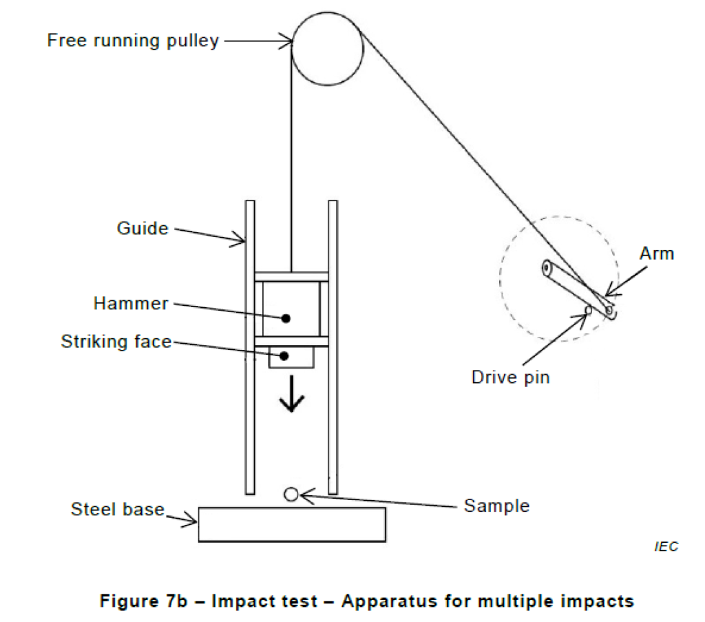
of steel which transmits the impact to the cable sample. When repeated impacts are required
(say, more than five), a more practical apparatus, as shown in Figure 7b, is used, which
allows multiple impacts by a drop hammer. The apparatus shall be arranged to impart minimal
friction to the moving weight/hammer.
NOTE This issue of friction has been found to be a particular problem when the apparatus is used at temperature
extremes.
In both cases, other equivalent apparatus may also be used.
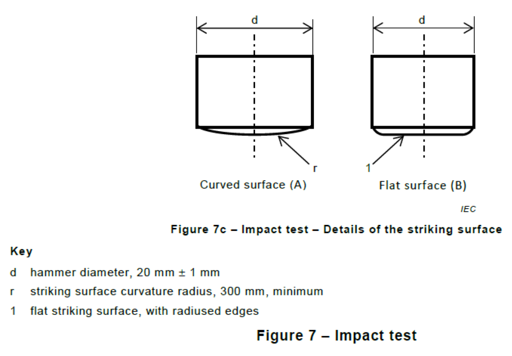
The striking surface shall either be flat or have a curved surface with curvature radius of no
less than 300 mm. If using a flat striking surface, the edges of the face shall be radiused to
avoid a stress concentration riser, Figure 7c, detail B. If using a 300 mm curvature radius
striking surface, then the surface may also be a spherical segment, as shown in Figure 7c,
detail A, since for such a large curvature radius this gives an equivalent test method to that
when using a rounded cylinder,.
The radius on the edge on the flat striking surface and on the 300 mm curvature radius
striking surface shall be approximately 0,5 mm.
The apparatus shall include any optical test equipment needed to measure the changes in
optical performance as required in the detail specification, and specified in Method A
(Transmitted power) of IEC 60793-1-46:2001.
6.4 Procedure
Unless otherwise specified, the conditions for testing shall be in accordance with standard
atmospheric conditions.
The mass of the weight or drop hammer and the height from which it falls shall be adjusted to
give the value of impact energy shown in the detail specification. The number and rate of
impacts, and their location on the sample shall be as specified in the detail specification.
6.5 Requirements
The acceptance criteria for the test shall be as stated in the detail specification. Typical failure
modes include loss of optical continuity, degradation of optical transmittance or physical
damage to the cable.
6.6 Details to be specified
The detail specification shall include the following:
a) number of impacts;
b) impact energy;
c) test temperature;
d) radius of the striking surface if other than specified herein;
e) frequency of multiple impacts (if any);
f) location of impacts on the sample;
g) if optical continuity or change in transmittance is to be measured.
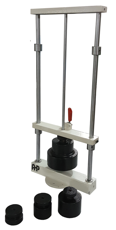
Impact Tester for Optical Cables According to IEC 60794-1-21 Method E4
- Hard chrome guide shafts
- Manual release of weight
- geometry of striker as standard
- 4 weights are included