
23.1 Object
This measuring method applies to optical fibre cables which are tested by temperature cycling in order to determine the stability behaviour of the attenuation of cables submitted to temperature changes.
Changes in the attenuation of optical fibre cables which may occur with changing temperatures are generally the result of buckling or tensioning of the fibres resulting from differences between their thermal expansion coefficient and the coefficients of the cable strength and jacketing members. Test conditions for temperature-dependent measurements shall simulate the worst conditions.
This test can be used either for monitoring cable behaviour in the temperature range which may occur during storage, transportation and usage or to check, in a selected temperature range (usually wider than that required for the above-mentioned case), the stability behaviour of the attenuation connected to a substantially microbend-free situation of the fibre within the cable structure.
23.2 Sample
The sample shall be a factory length or a sample of sufficient length as indicated in the detail specification but, nevertheless, of length appropriate to achieve the desired accuracy of attenuation measurements. A sufficient number of fibres distributed over the cable structure should be tested, as defined in the detail specification.
In order to gain reproducible values, the cable sample shall be brought into the climatic chamber as a loose coil or on a reel.
The ability of the fibre(s) to accommodate differential expansion and contraction (for example by slipping within the cable) could be influenced by the bending radius of the cable. Sample conditioning should, therefore, be realized as close as possible to normal usage conditions. Potential problems are due to an actual difference between the expansion coefficients of the test sample and of the holder (reel, basket, plate, etc.) which can induce, during thermal cycles, a significant effect on the test result if “no effect” conditions are not completely fulfilled. Parameters of influence are mainly the details of conditioning, the type and material(s) of the holder, the diameter of the sample coil or reel, etc.
General recommendations include the following:
a) The winding diameter shall be large enough to keep the ability of the fibre to accommodate differential expansion and contraction. A winding diameter substantially greater than the value selected for cable delivery may be necessary.
b) Any risk of cable expansion (or contraction) limitation created by conditioning shall be suppressed. In particular, special care should be taken to avoid residual tension on the cable during the test. For example, a tight winding on a drum is not recommended as it can limit cable contraction at low temperature. On the other hand, a tight multilayer winding can limit expansion at high temperature.
c) the use of loose winding is recommended, for example large diameter coils, cushioned reels with a soft layer or zero tension facility device, etc.
When necessary, in order to limit the length of the cable under test, it is permissible to connect several fibres of the cable and to measure the connected fibres. The number of connections shall be limited and they should be located outside the climatic chamber.
23.3 Apparatus
The apparatus consists of:
a) an appropriate attenuation measuring apparatus for the determination of attenuation change (see the test methods of IEC 60793-1-40);
b) a climatic chamber of a suitable size to accommodate the sample (see 22.2) and whose temperature shall be controllable to remain within ±3 °C of the specified testing temperature.
One example of a suitable chamber is given in Clause 2, test Nb, of IEC 60068-2-14.
23.4 Procedure
a) Initial measurement
The sample shall be visually inspected and a basic value for attenuation at the initial temperature shall be determined.
Pre-conditioning conditions shall be agreed between customer and supplier.
b) Conditioning
1) The sample at ambient temperature shall be introduced into the climatic chamber which is also at that temperature.
2) The temperature in the chamber shall then be lowered to the appropriate low temperature TA at the appropriate rate of cooling.
3) After temperature stability in the chamber has been reached, the sample shall be exposed to the low temperature conditions for the appropriate period t1.
4) The temperature in the chamber shall then be raised to the appropriate high temperature TB at the appropriate rate of heating.
5) After temperature stability in the chamber has been reached, the sample shall be exposed to the high temperature conditions for the appropriate period t1.
6) The temperature in the chamber shall then be lowered to the value of the ambient temperature at the appropriate rate of cooling. This procedure constitutes one cycle (see Figure 29).
7) The sample shall be subjected to two cycles unless otherwise required in the relevant detail specification.
8) The relevant detail specification shall state:
i) the change of attenuation and inspection checks during conditioning,
ii) the period(s) after which checks are to be carried out.
9) Before removal from the chamber, the sample under test shall have reached temperature stability at ambient temperature.
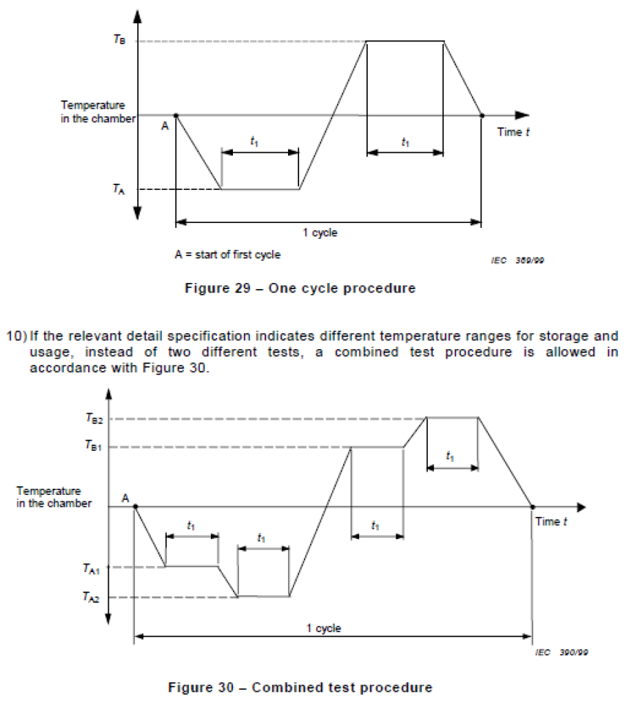
11) The values of TA, TB and t1 and the rate of cooling (or heating) shall be specified in the detail specification.
Depending on the cable construction, the temperature of the cable core could differ from the temperature of the climatic chamber.
c) Recovery
1) If the ambient temperature is not the standard atmospheric condition to be used for testing after removal from the chamber, the sample shall be allowed to attain temperature stability at this latter condition.
2) The relevant detail specification may call for a specific recovery period for a given type
of sample.
23.5 Requirements
The acceptance criteria for the test shall be as stated in the detail specification. Typical failure modes include loss of optical continuity, degradation of optical transmittance or physical damage to the cable.
23.6 Details to be specified
The detail specification shall include the following:
a) cable sample length;
b) number of fibres;
c) length of the fibre under test;
d) type of connection between fibres (if any);
e) type of winding:
1) coil, reel, other (to be stated, in case of a cushioned reel, the type of cushioning and material used),
2) winding diameter,
3) single or multilayer,
4) winding tension and zero tension facility device (if any);
f) type of measurement equipment;
g) launching conditions;
h) temperature cycle diagram1);
i) number of cycles;
j) humidity levels at each temperature extreme (if any);
k) change of attenuation at a specified wavelength as a function of temperature cycling4)
Thermal Cycling Tester for Optical Cables According to IEC 60794-1-2/F1
- Temperature range -30… 100 °C (Other ranges on request)
- Chamber size 1000*1000*1000 mm (Other sizes on request)
- SS304 internal chamber
- Control by computer
- Graphing the data
- Windows-based software
- USB cable for connection to computer