
10.1 Object
The purpose of this test is to determine the ability of an optical fibre cable to withstand repeated bending.
10.2 Sample
10.2.1 Sample length
The sample length shall be sufficient to carry out the specified test. When only physical damage is to be evaluated the length may range from 1 m (for example for small diameter jumper cords or duplex cables) to 5 m (for larger diameter cables). Longer lengths may be necessary to permit optical measurements.
10.2.2 Termination
The sample shall be terminated at each end in a connector, or in a manner such that the fibres, sheathings and any strain members are clamped together in a representative manner. The clamps on the bending apparatus may be adequate, or the sample may be long enough that no restraint is needed.
10.3 Apparatus
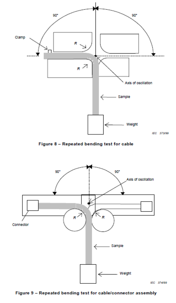
The apparatus shall permit a sample to be bent backwards and forwards through angles up to 180°, the two extreme positions making an angle of 90° on both sides of the vertical, whilst the sample is subjected to a tensile load. For testing cable, a suitable apparatus is shown in Figure 8. For testing a cable/connector assembly, a suitable apparatus is shown in Figure 9. Other equivalent apparatus may be used.
The bending arm shall have an adjustable clamp or fixture to permit holding the cable securely during the entire test, without crushing the optical fibres or inducing optical loss. For connectorized cables, a connector may be used to hold the cable on the bending arm. The apparatus shall be capable of cycling. Displacing the sample from the vertical position to the extreme right position, then oscillating to the extreme left position and returning to the original vertical position is considered to be one cycle. Unless otherwise specified in the detail specification, the bending rate shall be approximately one cycle in 2 s.
The apparatus shall include any optical test equipment needed to measure the changes in optical performance as required in the detail specification, and specified in method A
(Transmitted power) of IEC 60793-1-46.
10.4 Procedure
a) Unless otherwise specified, the conditions for testing shall be in accordance with standard atmospheric conditions.
b) The procedure can be defined by six steps:
- step 1: precondition the sample at standard atmospheric conditions for 24 h;
- step 2: fix the sample to the apparatus, as shown in Figures 8 and 9;
- step 3: apply the weight, as shown in the detail specification;
- step 4: measure acceptance criteria parameters to establish baseline values;
- step 5: carry out repeated bending for the number of cycles specified in the detail
specification; - step 6: carry out acceptance criteria parameter measurements. If necessary, the sample
may be removed from the apparatus for visual examination.
10.5 Requirements
The acceptance criteria for the test shall be as stated in the detail specification. Typical failure
modes include loss of optical continuity, degradation of optical transmittance or physical
damage to the cable.
10.6 Details to be specified
The detail specification shall include the following:
a) number of cycles;
b) mass of the weight;
c) bending radius R.
Repeated Bending tester, According to IEC 60794-1-2 Method E6
- Bending angle +-90 degrees
- Frequency 10-30 cycles/min
- Bending radius 75, 200, 300 mm (other sizes on request)
- Basic model is with a digital indicator (touch screen on request)
- Digital definition of number of cycles