
6 Method E2: Abrasion
6.1 Method E2A: Abrasion resistance of optical fibre cable sheaths
6.1.1 Object
The abrasion resistance of optical fibre cables has two aspects:
a) the ability of the sheath to resist abrasion;
b) the ability of cable markings to resist abrasion.
The purpose of this test is to determine the ability of an optical fibre cable sheath to resist abrasion. Abrasion testing of cable markings is method E2B.
6.1.2 Sample
The sample shall be of a length sufficient to carry out the specified test. A typical length is 750 mm.
6.1.3 Apparatus
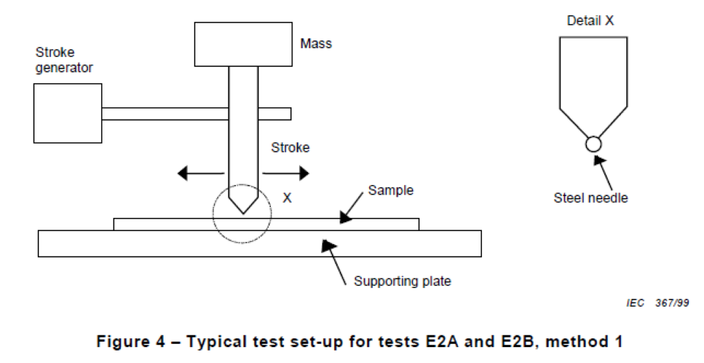
The abrasion test rig consists of a device designed to abrade the surface of the cable in both directions parallel to the longitudinal axis of the cable over a length of 10 mm ± 1 mm at a frequency of 55 cycles/min ± 5 cycles/min. One cycle consists of one abrading edge movement in each direction.
The abrading edge shall be a steel needle with a diameter as specified in the detail specification.
A typical apparatus is shown in Figure 4.
6.1.4 Procedure
a) Unless otherwise specified, the conditions for testing shall be in accordance with standard atmospheric conditions.
b) Securely attach the cable sample, measuring approximately 750 mm in length, to the supporting plate by means of cable clamps. The abrading edge shall be loaded with the mass necessary to provide the force stated in the detail specification whilst avoiding shock on the cable.
Four tests shall be made on each sample, with the sample moved forwards 100 mm between tests and rotated through an angle of 90°, always in the same direction.
6.1.5 Requirements
There shall be no perforation of the sheath and optical continuity shall be maintained after performing the number of cycles specified in the detail specification.
6.1.6 Details to be specified
The detail specification shall include the following:
a) number of cycles;
b) diameter of needle (method 1);
c) force applied.
6.2 Method E2B: Abrasion resistance of optical fibre cable markings
6.2.1 Object
The abrasion resistance of optical fibre cables has two aspects:
a) the ability of the sheath to resist abrasion;
b) the ability of cable markings to resist abrasion.
The purpose of this test is to determine the ability of markings of optical fibre cables to resist abrasion. Abrasion testing of cable sheaths is method E2A.
Depending on the kind of marking and as indicated in the detail specification, one of the
following two methods shall be used:
- method 1, suitable for rigid marking types like embossing, indenting and sintering;
- method 2, applicable to marking types other than embossing, indenting and sintering.
6.2.2 Sample
The sample shall be of a length sufficient to carry out the specified test. A typical length is
750 mm.
6.2.3 Apparatus
6.2.3.1 Method 1
A typical apparatus is shown in Figure 4.
The device is designed to abrade the marking of the cable parallel to the longitudinal axis of
the cable over a length of 40 mm, at a frequency of 55 cycles/min ± 5 cycles/min. One cycle
consists of one abrading edge movement in each direction.
The abrading edge shall be a steel needle with a diameter of 1 mm or as specified in the detail
specification.
6.2.3.2 Method 2
The apparatus consists of:
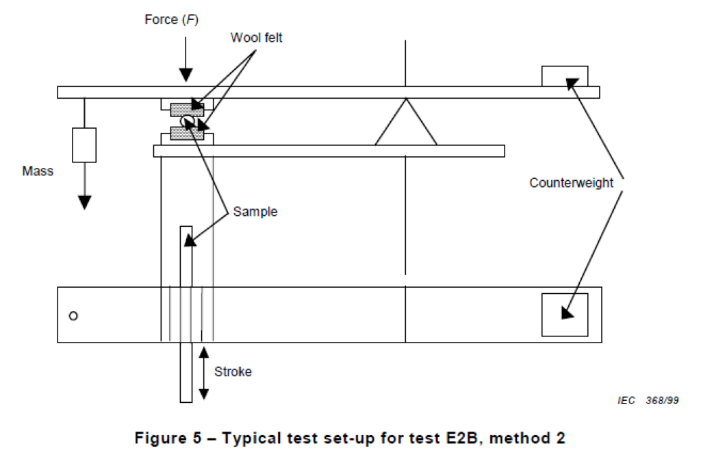
a) a test set-up, to apply a force to the wool felt. A typical example is shown in Figure 5;
b) a wool felt, colour white;
c) masses to apply a force to the sample.
6.2.4 Procedure
Unless otherwise specified, the conditions for testing shall be in accordance with standard atmospheric conditions.
6.2.4.1 Method 1
Securely attach the cable sample, measuring approximately 750 mm in length, to the supporting plate by means of cable clamps. Carry out the test with the sample mounted so that the marking is directly under the abrading edge. The abrading edge shall be loaded with the mass necessary to provide the force specified in the detail specification whilst avoiding shock on the cable.
6.2.4.2 Method 2
A sample of cable containing markings shall be laid between the two parts of the wool felt. The wool felt shall be thoroughly impregnated with water.
The normal force (F) given in the detail specification shall be applied to the markings on the sample which is moved back and forth over a length of 100 mm. The number of cycles shall be specified in the detail specification.
6.2.5 Requirement
The marking shall be legible at the completion of the test after the number of cycles specified in the detail specification.
6.2.6 Details to be specified
The detail specification shall include the following:
a) number of cycles;
b) method used;
c) diameter of needle (method 1);
d) force applied.
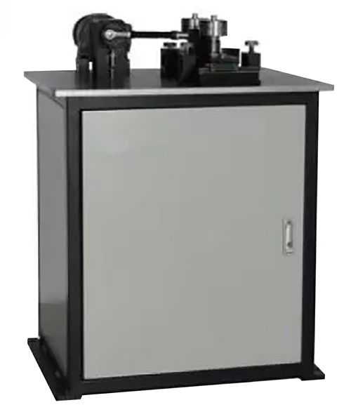
Optical Cable Abrasion Tester According to IEC 60794-1-2 Method E2
- Digital counter for number of travels
- 55±5 Times/min travel speed
- Counter weight bracket 5N×2
- Counter weight 5N×2, 10N×2
- Abrasion travel 10mm ( for sheath anti-abrasion test), 40mm (for mark anti-abrasion test)