
4 Test method principle
The material under test shall be heated in a stream of dry air and the gases shall be absorbed in 0,1 M sodium hydroxide solution contained in wash bottles. The amount of halogen acid shall then be determined by acidifying the solution with nitric acid, adding a measured volume of 0,1 M silver nitrate solution and back titrating the excess with 0,1 M ammonium thiocyanate, using ferric ammonium sulphate as the indicator.
NOTE 1 Other analytical methods having at least the same precision may be used, but in case of dispute the method given in this standard is the one to use.
NOTE 2 Although both hydrogen chloride and hydrogen bromide are detected by this analytical method, the halogen acid content is reported as if all the halogen acid is hydrogen chloride.
5 Test apparatus
5.1 General
The apparatus is shown in Figures 1 to 5.
The assembly of the components which constitute the test apparatus shall be leak-tight. The connecting distances between the quartz glass tube and the first bottle and between subsequent bottles shall be as short as possible. Glass or silicone rubber tubing shall be used for these connections.
NOTE 1 At the exit side of the quartz glass tube, as close to the end as possible, it is permitted to place a plug of silica wool to aid collection of condensates.
NOTE 2 A third empty bottle, of the same size as the gas washing bottles, placed before the gas washing bottles, may be used to improve safety, i.e. to prevent suck back of water into the quartz glass tube.
5.2 Tube furnace
The length of the heating zone of the furnace shall be within the range 480 mm to 620 mm, and its inside diameter shall be within the range 38 mm to 62 mm. It shall be equipped with an adjustable electrical heating system.
5.3 Quartz glass tube
For the test, a quartz glass tube shall be introduced into the tube furnace. The tube shall be approximately concentric to the furnace. It shall be resistant to the action of corrosive gases. The inside diameter of the tube shall be within the range 30 mm to 46 mm. The tube shall protrude on the entrance side of the furnace by a length of between 60 mm to 200 mm, and on the exit side by between 60 mm to 100 mm. The initial clearance shall allow for thermal expansion. For the purposes of measurement of the protrusion distances, the tube shall be regarded as that part of essentially constant diameter.
NOTE The outer diameter of the tube should be chosen with due regard to the inside diameter of the tube furnace. Prior to each test, the tube shall be cleaned throughout its length by being calcined at approximately 950 °C.
5.4 Combustion boats
The combustion boat shall be made of porcelain, fused quartz or soapstone and shall have the following dimensions:
– external length: within the range 45 mm to 100 mm;
– external width: within the range 12 mm to 30 mm;
– internal depth: within the range 5 mm to 10 mm
NOTE The dimensions of the boat should be chosen with due regard to the inside diameter of the quartz tube. The preferred method for insertion of the combustion boat into the quartz glass tube is shown in Figure 1.
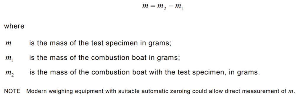
Prior to each test, the combustion boat shall be washed and calcined in a muffle furnace at approximately 950 °C for 4 h after which it shall be introduced into a desiccator and cooled to ambient temperature. The combustion boat shall then be weighed to an accuracy of 0,1 mg. This weight m1 shall be recorded.
5.5 Bubbling devices for gases
At the exit of the quartz glass tube, the evolved gases shall be passed through two wash bottles (see Figure 2), each containing at least 220 ml of 0,1 M sodium hydroxide solution. A magnetic stirrer shall be introduced in the first gas washing bottle to get a good swirling motion and an effective absorption of the combustion gases. The tubes into the wash bottles shall have a maximum internal diameter at their tip of 5 mm, in order to aid absorption. The height of the liquid above the end of the tube shall be (110 ±10) mm in each bottle.
NOTE Use of a standard laboratory glass bottle of approximately 50 mm internal diameter will enable this requirement to be met.
The gas used for combustion shall be air.
The flow rate of air introduced into the quartz glass tube shall be adjusted according to the actual internal cross-sectional area of the tube, such that the speed of air flowing across the sample is approximately

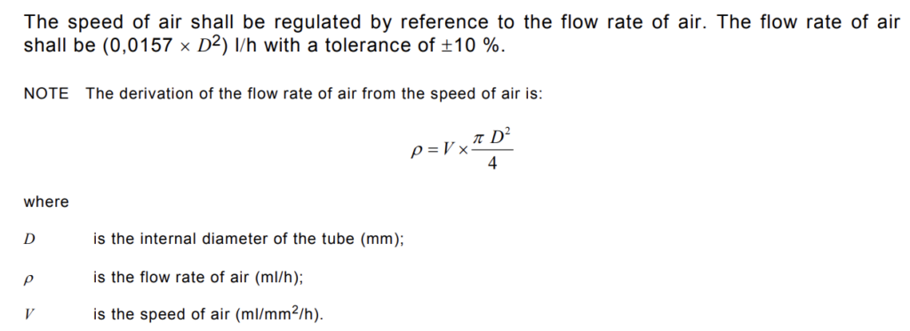
The air supply shall be adjusted and controlled by a needle valve, and the flow rate monitored by a flowmeter of the appropriate range.
The air supplied shall be selected from one of the following methods:
Method 1
This method uses synthetic air or compressed air from a bottle. The air shall be introduced on the inlet side of the quartz glass tube (see Figure 3).
Method 2
This method uses a laboratory compressed air supply. The air shall be introduced on the inlet side of the quartz glass tube and shall be be filtered and dried (see Figure 4).
Method 3
This method uses the ambient air of the laboratory. The air shall be filtered and dried. In this case, the mixture of air and combustion gas shall be sucked by a pump. (See Figure 5.)
5.7 Analytical balance
The balance shall have a precision of ±0,1 mg.
5.8 Laboratory glassware
For the titration, the following laboratory glassware shall be available:
– 20 ml pipette;
– 100 ml pipette;
– one mark volumetric flask in accordance with ISO 1042 with 1000 ml capacity;
– conical flask with 250 ml to 500 ml capacity;
– burette in accordance with ISO 385-1.
5.9 Reagents
For the analysis, the following reagents of a recognized analytical quality shall be used. Demineralized or distilled water shall be of a purity at least Grade 3 in accordance with ISO 3696.
a) concentrated nitric acid: about 65 %, with a specific gravity ρ of approximately 1,40 g/ml;
b) nitric acid, approximately 6 M;
c) 0,1 M silver nitrate;
d) nitrobenzene, toluene or iso-amyl alcohol;
e) an approximately 40% weight/volume solution of ferric ammonium sulphate;
f) 0,1 M ammonium thiocyanate solution.
WARNING Nitrobenzene is regarded as highly toxic. Toluene or iso-amyl alcohol are safer alternatives.
6 Test specimen
6.1 General
Two test specimens, each consisting of (750 ± 250) mg of the material to be tested, shall be prepared. Each test specimen shall be taken from a sample representative of the material. Each test specimen shall be cut into a number of smaller pieces.
NOTE Pieces with a maximum dimension of 3 mm have been found to be suitable.
6.2 Conditioning of specimen
The prepared test specimens shall be conditioned for at least 16 h at a temperature of (23 ±2) °C and a relative humidity of (50 ± 5) %.
6.3 Mass of specimen
Weigh the combustion boat ( m1) to an accuracy of 0,1 mg (see 5.4). After conditioning, the test specimen shall be put into the combustion boat and evenly distributed on the bottom of the boat, which shall be weighed to an accuracy of 0,1 mg, The weight ( m2 ) shall be recorded.
The mass m of the test specimen shall be calculated as follows:
7 Test procedure
7.1 General
The test procedure and determination shall be carried out on each test specimen.
7.2 Test apparatus and arrangement
The test procedure defined in this clause shall be carried out using the apparatus detailed in Clause 5.
7.3 Heating procedure
7.3.1 Determination of heating regime
The empty combustion boat shall be inserted into the quartz glass tube and placed
approximately in the centre of the tube furnace.
The flow rate of air shall be adjusted by means of a needle valve to the value specified in 5.6
and shall be kept constant during the determination.
Position a thermocouple, or other suitable temperature measuring device (suitably protected against corrosion), at the test specimen point in the empty combustion boat. The combustion boat shall be heated at an approximately uniform heating rate over a period of (40 ± 5) min in order to raise the temperature recorded by the thermocouple to (800 ± 10) °C, after which it shall be maintained at that temperature for (20 ± 1) min.
Determine from this procedure a heating regime which will ensure that the required test specimen heating rate and temperature is achieved.
7.3.2 Test specimen heating procedure
The combustion boat containing the test specimen shall be inserted into the quartz glass tube and placed approximately in the centre of the tube furnace.
The flow rate of air shall be adjusted by means of a needle valve to the value specified in 5.6
and shall be kept constant during the test. The test specimen shall be heated using the heating regime determined in 7.3.1.
WARNING The operator should take precautions, e.g. the wearing of eye protection and suitable protective clothing, because certain materials ignite quickly, and can cause “blow back” of hot gases. Care should also be taken to avoid over-pressurization of the system, and to allow for venting of exhaust gases. Guidance on the avoidance of “blow back” is given in NOTE 2 of 5.1.
7.4 Washing procedure
Following the heating procedure, all the bottles used shall be disconnected, and the contents washed into a 1 000 ml volumetric flask. Using distilled or demineralized water, the bottles, the connecting links and, after cooling, the end of the quartz glass tube including the silica wool (if used) shall also be washed into the flask, and the contents made up to 1 000 ml.
7.5 Determination of halogen acid content
7.5.1 Blank test
Prior to conducting a test on a test specimen, a blank test shall be carried out using the test procedure given in 7.3.2 but without a test specimen in the combustion boat.
After cooling to ambient temperature, 200 ml of the solution shall be measured into a conical flask using a suitable pipette, and the following reagents introduced successively:
a) approximately 4 ml of concentrated nitric acid;
b) 20 ml of 0,1 M silver nitrate, measured with a pipette;
c) approximately 3 ml of either nitrobenzene, toluene or iso-amyl alcohol.
The contents shall be well shaken to achieve conglomeration and coating of the silver halide that is formed by the reaction.
1 ml of a 40 % (weight/volume) aqueous solution of ferric ammonium sulphate containing a few drops of 6 M nitric acid shall then be added and the whole mixed together. The solution shall then be titrated with 0,1 M ammonium thiocyanate solution using a burette and the whole shaken or stirred vigorously. The end-point shall be the red end-point for the titration. The volume, B, of 0,1 M ammonium thiocyanate solution shall be recorded.
NOTE It is recommended that the blank test be carried out prior to each testing campaign and whenever a new batch of sodium hydroxide solution, silver nitrate solution, ammonium thiocyanate solution or distilled or demineralized water is started.
7.5.2 Material test
The test procedure given in 7.3.2 shall be carried out with a test specimen in the combustion boat.
After cooling to ambient temperature, 200 ml of the solution shall be measured into a conical flask using a suitable pipette and the following reagents introduced successively:
a) approximately 4 ml of concentrated nitric acid;
b) 20 ml of 0,1 M silver nitrate, measured with a pipette;
c) approximately 3 ml of either nitrobenzene, toluene or iso-amyl alcohol.
The contents shall be well shaken to achieve conglomeration and coating of the silver halide that is formed by the reaction.
1 ml of a 40 % (weight/volume) aqueous solution of ferric ammonium sulphate containing a few drops of 6 M nitric acid shall then be added and the whole mixed together. The solution shall then be titrated with 0,1 M ammonium thiocyanate solution using a burette and the whole shaken or stirred vigorously. The end-point shall be the red end-point for the titration.
The volume, A, of 0,1 M ammonium thiocyanate solution shall be recorded.
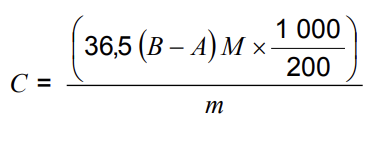
7.5.3 Halogen acid content calculation
The amount of halogen acid, expressed as milligrams of hydrochloric acid per gram of test specimen taken, shall be determined according to the formula:
where
A is the volume in ml of 0,1 M ammonium thiocyanate solution used in the test specimen determination;
B is the volume in ml of 0,1 M ammonium thiocyanate solution used in the blank test determination;
C is the amount of halogen acid expressed in milligrams of hydrochloric acid per gram of the test specimen;
m is the mass of test specimen taken in grams;
M is the molarity of ammonium thiocyanate solution;
36,5 is the molar mass of hydrogen chloride.
8 Evaluation of the test results
The halogen acid gas content of the material, Cm, shall be taken as the mean of the determination of the two test specimens.
The individual values shall not vary from the mean by more than ±10 % where the halogen acid gas content is ≥ 5 mg/g.
Record C = 5 when the amount of halogen acid is less than 5 mg/g.
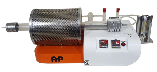
Halogen Acid Gas Content Tester According to IEC 60754-1
- Digital timer
- Flowmeter
- PID temperature controller
- High-temperature sensitivity
- Sample holders available
- Coated with electrostatic powder paint
- Operating voltage: 220V, 50 Hz.
- pH-meter and Conductivity-meter (optional)
- Resolution (pH-meter): 0.1
- Precise balance ±0,1 mg-220g (is as option)
- Length of heating zone is 480mm
- Internal diameter of quartz tube 36 mm
- Resolution (conductivity-meter): 1
- Quartz tube
- 20 ml pipette
- Volumetric flask 1000 ml capacity
- 100 ml pipette
- Chemicals are not included
- Burette in accordance with ISO 385-1
- Wash bottles at least 220 ml
- Conical flask with 250 ml to 500 ml capacity
- Sliding sample holder for easy placement of sample inside tube
- Alumina sample boat