

Unpacking of the machines
First of all, gently unpack the machine. Normally, a full pack of the machine will come to the customer with:
- Pressure unit (with power stabilizer for computer if you ordered)
- Hot and/or cold water bath
- Connection hoses between pressure unit and water bath (1/4″ male-female connection)
- Computer and ergo arm for computer
- Connection hoses between sample pieces and end caps (two end quick coupling hoses)
- End caps for pipes according to your order
Place the bath and appropriate location in your lab. Be noted hydrostatic pressure testing will have some water vapor from the bath when you open the door and some water outlets from samples during assembly. Then it should be placed somewhere with a water drain, water supply, table for assembly of end caps, and proper ventilation for the vapor when you open the bath.
Open the door of the bath and see inside. there maybe some items of the order inside it. For opening there is no need for electric. Just connect the compressed air line (at least 6 bar) at the back of the bath and use the key on the panel to open the door. The door may get stuck during shipment, When you open it don’t be in front of the door to avoid injury.

Place the pressure unit on the side of the display of the water bath. Sample placement is as below picture:

Check the nameplate of the unit and bath, and prepare a proper electric panel with the proper cable size and elements on the back wall of the machine. The electric panel must include phase control, proper fuses and life protector and earth connection.
Water connections and drains
On the back side of the bath you will see panel for hydraulic connections. Theses include:
- Over drain connection
- Water inlet connection (Autofill line)
- Water drain of the bath
- hydraulic connection between bath and unit (Number of lines depends on the order)
- Compressed air in
For the first startup of the bath, please fill the tanks at least to the middle from the top. Unless you connect electricity and there is no water inside the tank, a failure of the heating resistance will occurs.
Use proper filters for the water inlet to the tank. Also take care when you put samples inside the bath, fully clean to be free of dirt. After filters, water will go to the auto-fill line (or fill line) in the back panel of the tank (Figure 1).

Connect hoses between the tank and pressure unit with male-female hoses (Figure 1 and Figure 2).

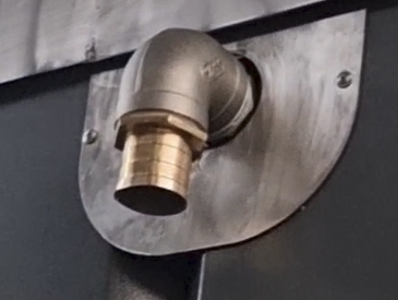
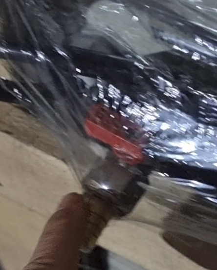
Connect the outlet line of the tank to the inlet line of the pressure unit(Figure 3 and 4). There is a brass filter that need to be connected to the outlet of the tank to the pressure unit.

Connect the water over-drain and the water drain line of the tank to the drain line of the laboratory (Figure 5 and 6).


After you fill the water tank from top to the half height, you can connect electricity. The water tank includes an autofill line with a solenoid valve. After you connect electricity, water will fill up to the water level sensor automatically. Be sure you have filters between the laboratory line and the tank auto-fill line.

Connect the temperature sensor of the pressure unit to the tank.

Key Notes for Startup of Hot Water Bath for Hydrostatic Pressure Tester
1- Place bath in secure place so that at least 1 meter around it need to be empty for service and repair
2- According to the power of heating of bath you need electric panel with proper circuit breaker small size bath has 6KW power, medium size is 18KW, Big size is 30KW power
3- Bath has pneumatic door and need compressed air supply with pressure of minimum 6 bar
4- First step is a need for air supply to open the door of bath , air input is as below picture [Air], it is 6mm or 8mm air hose input
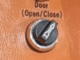
5- Then open the door via a key on main panel as below picture [Door (Open/close)]. For proper door open/close there are two flow valves on each pneumatic cylinder of the door that should be set properly for even door close and open.
6- Fill the bath with tapped water with very low level of hardness up to at least minimum height
7- Note: before filling water never connect electric power supply
8- Power supply is 380 V- 3ph with proper power for bath as per heating power
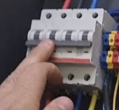
9- Connect the power supply cable as below picture. Yellow/green(it is shown with node on the wire) wire is null and other 3 are three phases.

10 -Connect the auto fill hose of the bath as below picture. it is equipped with level sensor and solenoid valve to automatically keep the heigh of water in bath.
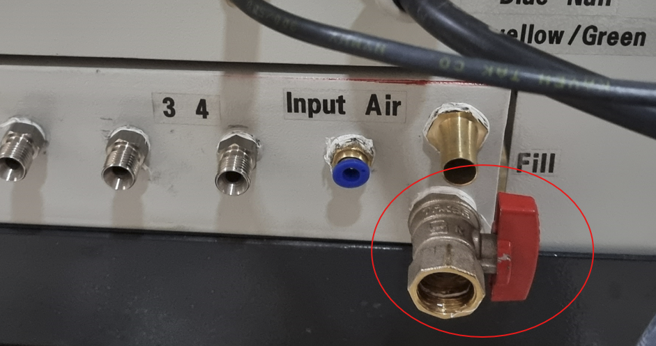
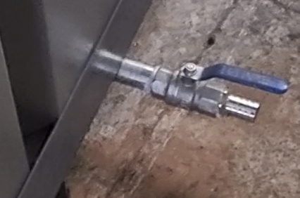
11- Close the outlet valve of bath that is placed somewhere beneath the bath as below picture. for safety of this valve during transport it is opened and keep somewhere along with goods that you received. Be sure that this valve need to be closed before filling of the water bath.
12- Connect drain hose. It is paced in the back top side of the bath
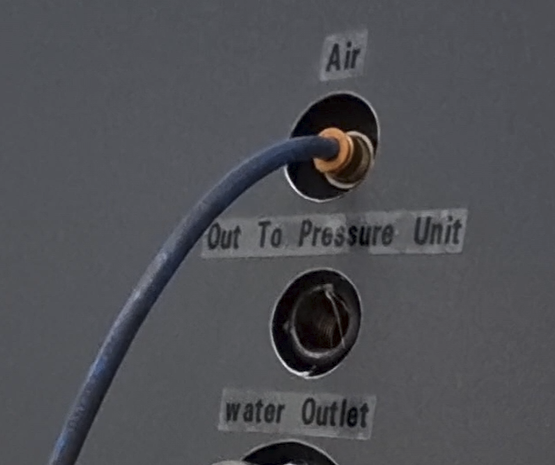
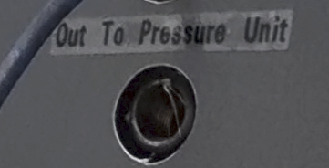
13- There is a outlet connection from the bath to pressure unit that you can use in case of inlet water to pressure unit. [Out to Pressure Unit]
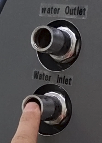
14- For the bath with heat exchanger, there are two hose connection that is water inlet and water outlet to the chiller. [Water outlet and water inlet]
15- Above hose connection of the bath will goes to the chiller connections as below pictures.

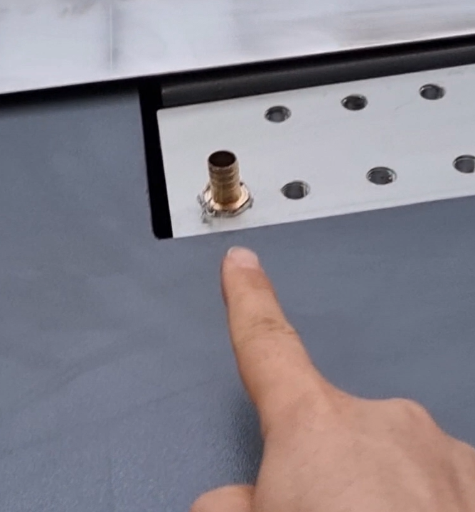
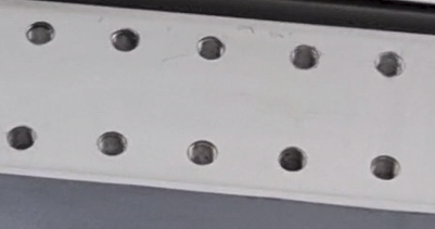
16- Bath has 2, 4 , 6, 8, …. number of inputs from pressure unit as per customer request. size of these inputs are 1/4inch female or as per customer request.
17- After connections of all hoses to the bath, please connect earth connection to the main body of the bath.
18- Now you can turn on main circuit breaker of the bath that is paced inside the main power panel
19- After power on of the machine, be sure that circulation pump is working. and the input valve of the reservoir for installation of heating elements is open. meaning that water circulation is complete from bath to heating element small tank and then back to the bath from upper corner side.
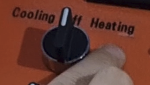
20- If bath has heating and also heat exchanger main panel includes a key named [cooling-off-heating]. This means that if target temperature is below present temperature and you need to cool down the bath temperature, turn this key to [cooling] side and vice verse. When you put it on cooling side, chiller will be working automatically unless chiller will not be working. Also if you put this key to heating side, first heating element will be on working and others will be active when you turn each heating element separately.
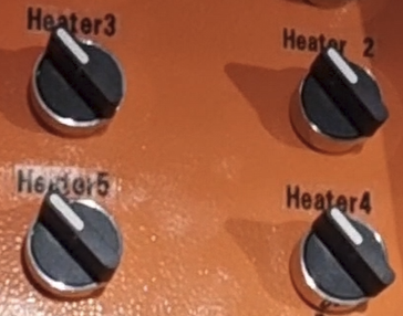
21- Other 4 heating element keys are shown in below picture.
22- Next step is setting temperature in the main controller of the bath. All parameters of the controller is shown in the other post.
23- Main notes: ground connection, filling water before electric connection, tapped and low hardness water use unless heating element will be blown rapidly, periodical change of water to be clean
Hydrostatic Pressure Test Unit Software
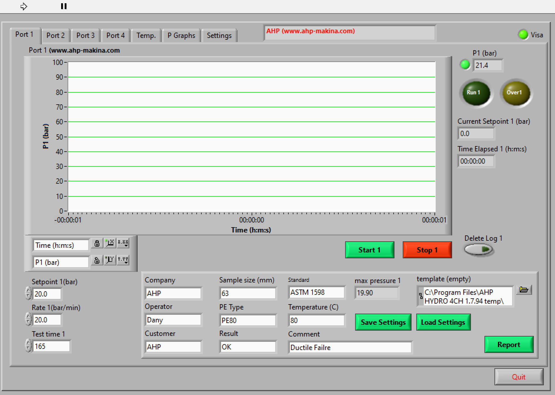
Port 1: it is the page related to station number of 1 of the hydro test unit
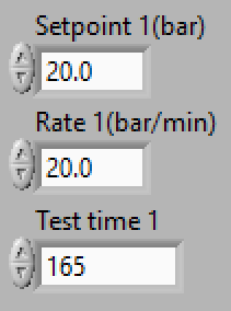
Setpoint1(bar): setpoint of requested pressure in bar
Rate1(bar/min): Rate of pressure increase, It is used mainly in burst test of pipes and fittings. because in burst test sample need to be burst in definite time of 60-70s. if you know approximate burst pressure of a sample piece, for example 50 bar, then set the rate to 50-60bar/min so that sample can be burst in about 60 seconds.
Test time1: It is test time set for line 1.
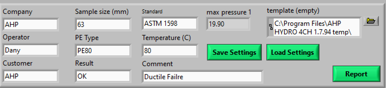
Company, Operator, Customer, Sample size, PE Type, Result, Standard, Temperature, Comment all are general parameter of the sample is going to be tested in station no.1
Save Settings: if operator want to save setting parameters as .txt file and load them the day next can use this key. be noted when saving the file name put .txt at the end of file name.
Load Settings: Used for loading general sample parameters
Report: Used for making Report of the station number 1 in MS WORD.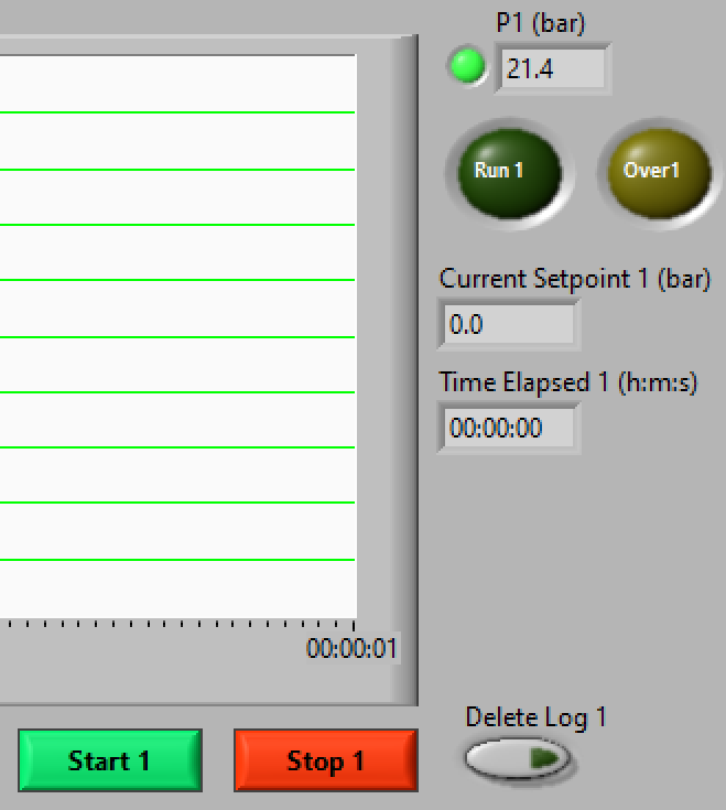
Delete log: When you want to start new test with line no.1 , before starting of the line click on the “delete log” so that log file being deleted and ready for next test.
If you want to continue the last test, you can click on start without deleting the log.
Run Led: It is green when the line is running
Current setpoint: When you set specific rate for pressure increase, program sets the pressure as per that input pressure increase rate. Current set is the current set pressure sent to the controller of the unit.
Start1: Start of the line 1 for testing and graphing
Stop1: Stop of line 1 for testing and graphing
P1: Current pressure of the line 1 in bar
When the green led is in red means that there is not any connection between software and machine.
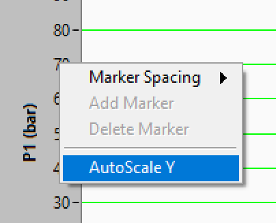
You can click on vertical line of the graph to set the Y axis to AutoScale mode. meaning that lower and upper limit of the vertical line is set as per current value of the pressure automatically. If you make this parameters OFF, you can define lower and upper limit of the graph manually. You can do the same setting for X axis of the pressure graph.
It shows maximum pressure applied to the line 1 after starting the line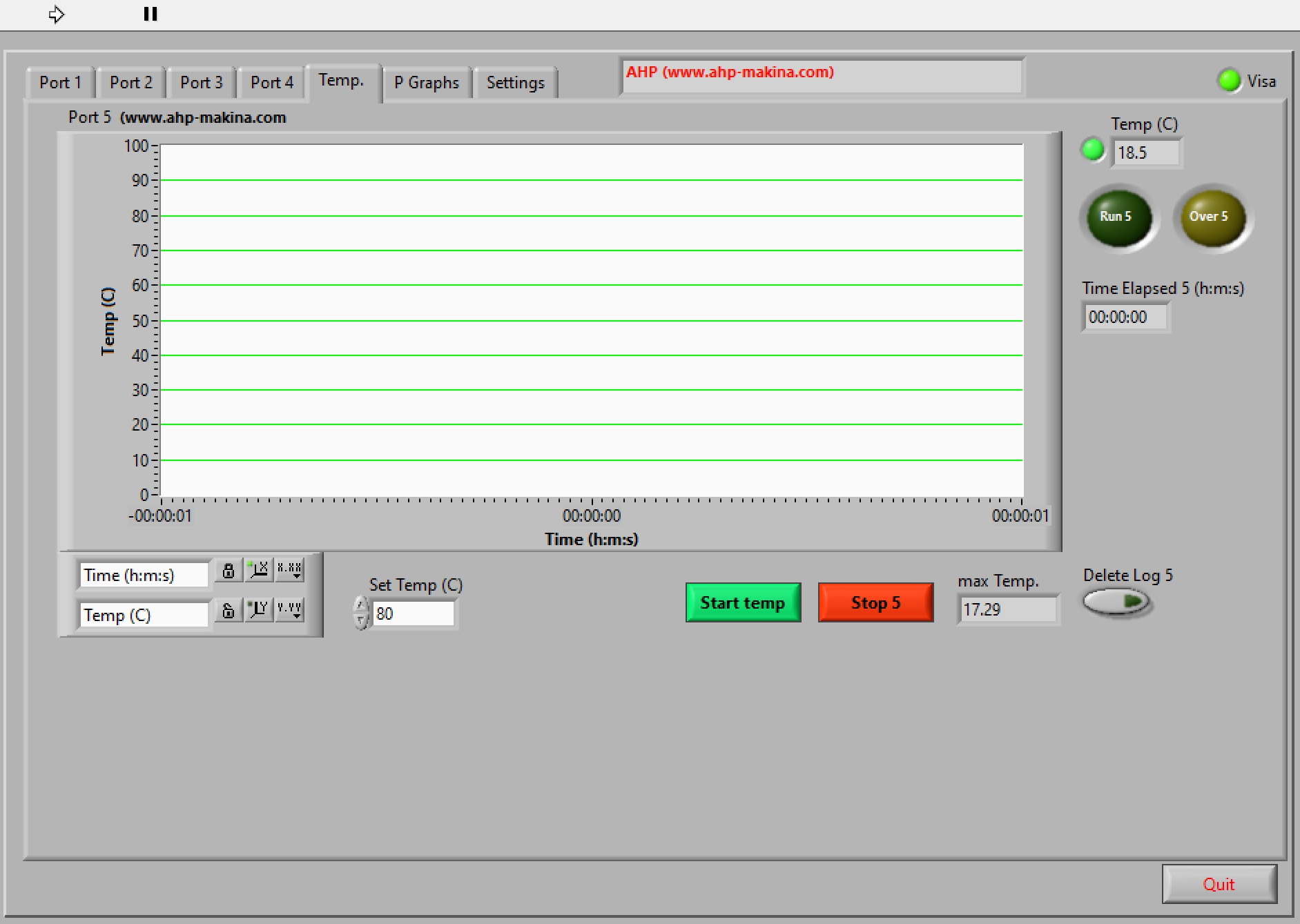

You have same setting for the Temp page of the software. When you start definite pressure line also click on “Start temp” for graphing the temperature of the test tank. after stop of the pressure line also stop the temperature monitoring and graphing.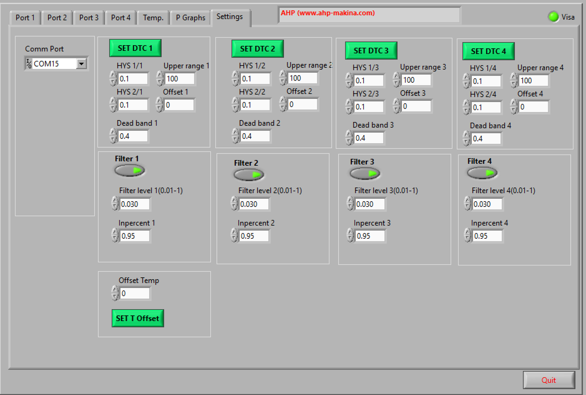

Inpercent1: means when the pressure of line 1 drops for definite percent, machine will automatically stops the line. suppose that you set this value to 0.95 , it means that 1-0.95=0.05, 0.05*100=5 when pressure drops suddenly for 5% in line one , machine recognize that sample burst. Set this value for small samples in high values like 0.95, 0.98, 0.97 … depending on the pipe size. for big pipe sizes when machine starts pressurizing of the sample, it expands and pressure drops time to time. Then when starting big pipe sizes set this parameter to small values like 0.85, 0.8, … after pressure reaches to set value you can set again to high value for recognizing even the leak of the sample and stopping of the line.
This filers the noises of the read pressure. less value for Filter level means stronger filter and more delay of the reading of the signal.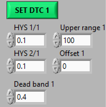
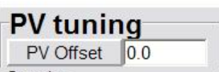
setting the parameters of the controller for line 1. HYS1/1 is the pressure value upper and lower of the set values that runs and stops the motor and pump. Dead band is the range around set point of pressure that controller does nothing. Offset is the pressure offset value for calibration and correction of the read pressure comparing to reference reading device. Upper range is the upper pressure range of pressure sensor. After setting of the proper parameters click on SET DTC1.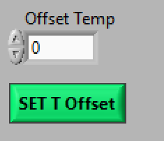
It is the temperature offset for reading temperature of tank. When calibrating read temperature of the tank comparing with reference reading device, you can set the offset value here and click “SET T Offset”.
When you want to turn off computer, dont forget to click on Quit. unless, last settings of the pressure in controllers of each line will be remained and when you turn on machine next time, it will start working automatically.
After clicking on Quit, if you want to run software again you can click on “right arrow key” on top left corner of the panel.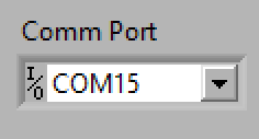
It is the communication port number of the computer to the machine. for more detailed guide about installation of the driver for communication of AHP machines with computer refer to link below:
Install RS485-USB Drive for AHP’s Products
When software is connected to machine, this led will be green, unless it is red color meaning there is not connection between software and machine.
Calibration of the Pressure unit
- Download driver
- Click on DTCOM_E.exe
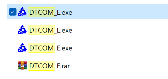
- Select COM port (Refer to COM port driver installation guide) and then click on “Auto Detect”.
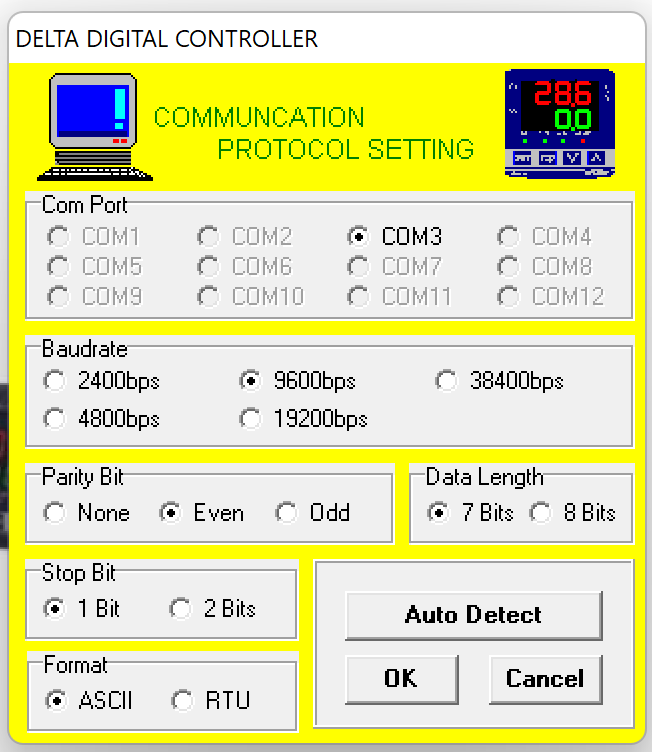
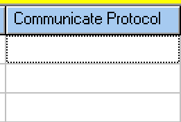
- After detection of some controllers, in the “communication protol” section click on one the detected items and then click “SET” then “Close”.


- Click on Monitor Icon.

- Select proper “Address”. In hydrostatic pressure testers from AHP, there are “number of lines+1” station address, for example in 4 station hydrostatic unit there are 5 address. 1 to 4 is related to pressure lines and 5 is related to temperature address. Select requested address for calibration.
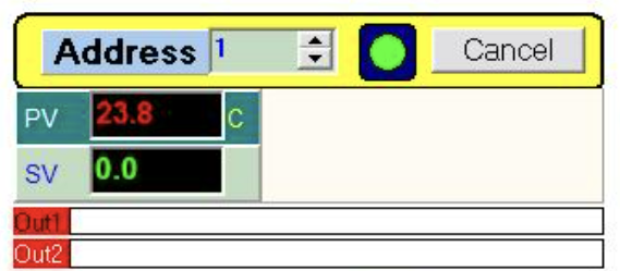

- In the bottom of page settings for the requested station address will be shown.
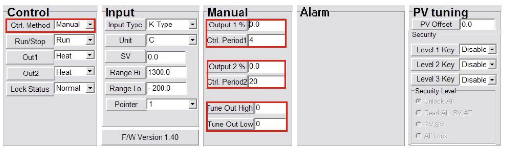
Calibration offset value. Be noted after set of proper value don’t forget to “ENTER”.
- Don’t change any other parameters of this page.
- You can do same procedure for temperature line as well.
Troubleshooting Hydrostatic Pressure Tester
Pressure Not Increase in the outlet
1- Check main power key is ON
2- Check software has connection to machine and led is green (refer to hydrostatic software guide post)
3- Check sound of electromotor if electric is connected when you start specific line
4- If motor is running when you start a line first of all check water inlet to the pump (Fig1)
5- Check if brass filter is OK, open the cap of brass filter and check if it is clean (Fig1)
6- Check the bypass valve if it is half open (Fig1)
7- Check the pressure relief valve is set (Turn right for pressure increase and left for pressure decrease) (Fig1)
8- Check if water is coming out from pump outlet hose (Fig1)
9- After checking main pump function and water connections and water inlet outlet to the pump next is solenoid valves block
10- Check if pressure lines needle valves are open (Fig2)
11- Check if when you run specific line, pressure line solenoid valves need to be electrized. Take a metal piece next to valve solenoid and it will be attracted like a magnet (Fig2)
12- Check if check valves(one way valves) are not blocked (Fig6)
13- Check if drain line needle valves are closed.
14- Check if all accumulators have pressure inside. accumulator pressure need to be less than minimum pressure you defined for a specific line. (Fig3)
15- For charging accumulator, just open the valve cap, open the valve and fill it with pressurized air or N2 gas, then close the valve and close the valve cap. (Fig3)
16- It is easy to change of elastomer membrane of accumulator. drain the pressure line, open the cap of accumulator and change the membrane. (Fig3)
17- Check pump oil level and fill in case of need (Fig4)
18- If pressure in one line going up then getting back down it has 3 main reason: one way valve on the pressure line block(Fig6), drain needle valves are open or you have leakage in the sample piece assembly.
19- If you don’t have connection between software and machine, first of all check the USB virtual com port (refer to com port installation guide post in info center), check DTC1000 controller RS485 and power port is tight. Check if DTC controllers has Run key in on side. Check if DTC1000 controllers have poser and leds on them are green without error. (Fig7 & Fig8)

20- If DTC1000 controllers are OK, then go to the overload relay if it not acted. if overload relay is acted just reset it. When DTC1000 controller has connection to PC anf you are running a line, DTC is working and motor has not acting, it is probably because of over load relay of motor acted. (Fig7)
21- Always check connection between software and machine. When everything in this regard is OK, two led on RS485 converter blinking when machine is working. Detailed comments about RS485 installation and checking is on specific post in info center.
22- When you don’t have leds on the DTC controllers ON, probability you have failed power 24V DC supply. check if led on power supply is on. Check input power and DC output power of DC supply.
Preventive Maintenance of Hydrostatic Pressure Test Machine
For proper using of hydrostatic pressure test unit, hot bath and end caps below considerations will make very long life-time of parts used inside the machine. For the valued customers note below brands used as internal parts with high quality.
1- Main pump: Bertollini Italy
2- Pressure sensors: WIKA Germany
3- Solenoid valves: ODE Italy
4- High pressure accumulators membrane: Italian brand
5- Temperature controller for Hot bath: Autonics Korea
6- Electric parts: Schneider Electric
Beside above mentioned high quality parts that are used, for long-life of the machine below predictive maintenance and maintenance procedure need to be considered by the operators.
Preventive Maintenance
- Water supply need to be filtered with low hardness value
- Samples need to be cleaned before putting them inside hot bath
- Sensors need to be checked every month to have accurate pressure value in all stations (with calibrated pressure read device)
- Temperature sensors need to be checked and internally calibrated every 6 month (with calibrated temperature readout)
- Water filters of hot bath and pressure unit need to be checked every month to be sure water is coming to pump properly
- Electric power coming to the computer need to be stabilized power source (preferably UPS is used)
- Automatic refill sensor and valve of hot bath need to be checked periodically to be sure about functioning
- Greasing the end caps o-rings will cause very less damage to them during assembly
- Every 3 months, water inside the hot bath need to be replaced in case of dirt come into that from outside when putting samples inside it
- check the oil level of main pump and add oil in case of need
Maintenance Operation
| Description | Frequency |
| Check if water main line is connected | Daily |
| Check if compressed air line is connected | Daily |
| Check if water inside bath is clean and if needed replace it | Weekly |
| Check the main compressed line pressure in the regulator | Daily – Before Startup |
| Check and replace the water filters of purifying system | When needed (If there is not any water comping out of the water purifying unit) – Yearly |
| Check if there is not any leakage from piping and fittings | Daily before and during the test |
| Check before power off of the machine , Need to click on “Quit” key on software | Daily |
| Check if you set proper value in “Inpercent” parameter for automatic stop of the line in case of sample burst. There is 2-step diagnose system for the machine to understand burst and leakage of the sample during testing. This will protect damage to the pump. | Daily |
| Check the user manual of the main pump Bertollini piston pumps | As required |
| Check if circulation pump of hot bath is working | Daily |
| Check if water level switch of the bath is working properly . Before startup of heating system of the bath be sure bath is full of water | Daily |
| Check if pneumatic door of bath working properly, this is important for safety. Before test start be sure to close the door | Daily |
| Check if overflow line of bath is working properly and not blocked | Weekly |
| Check if you have proper earthing connection to the body of the machine. This is very important especially in case of failures of heating resistance elements | Monthly |
| Check if supplied compressed air is dry. Wet compressed air will damage pump, digital pressure regulator… | Weekly and in machine startup |